Vecima Networks TRX2526Y 2.5 GHz Subscriber Transceiver User Manual
Vecima Networks Inc. 2.5 GHz Subscriber Transceiver Users Manual
UserManual.wiki
>
Vecima Networks
>
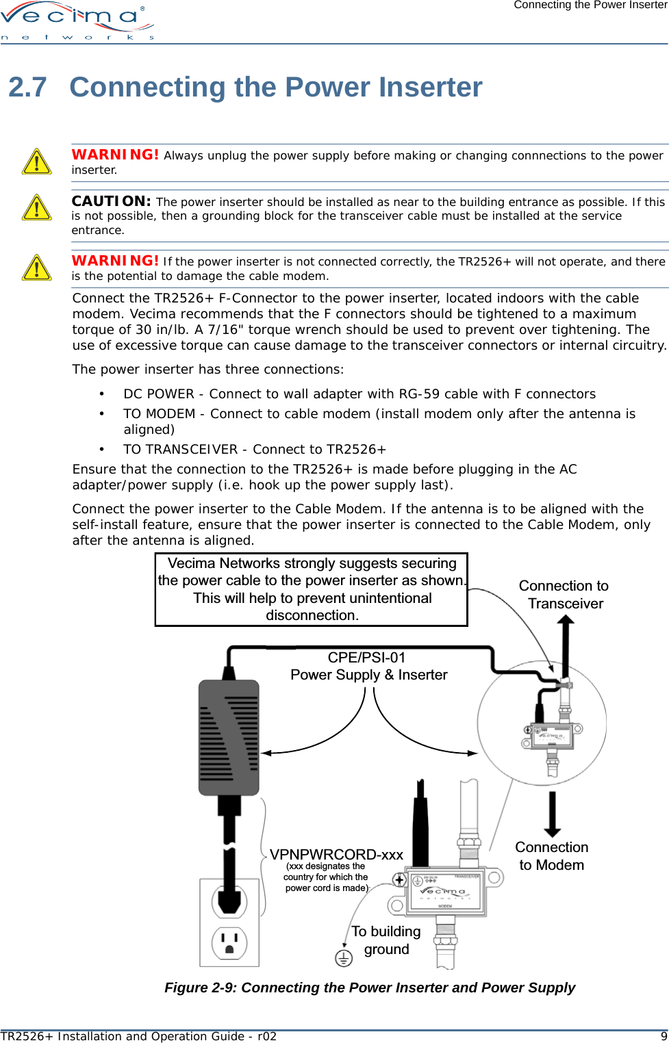
TRX2526Y User Manual
Users Manual
Navigation menu
Upload a User Manual
Namespaces
Wiki Guide
HTML
PDF
Info
Views
User Manual
Discussion / Help
Navigation