Vecima Networks WRM1151 2.4GHz 6 Channel DSSS Transceiver User Manual
Vecima Networks Inc. 2.4GHz 6 Channel DSSS Transceiver
UserManual.wiki
>
Vecima Networks
>
WRM1151 User Manual
>
Updated Manual
Contents
1.
Updated Manual
2.
Users Manual
Updated Manual
Navigation menu
Upload a User Manual
Namespaces
Wiki Guide
HTML
PDF
Info
Views
User Manual
Discussion / Help
Navigation

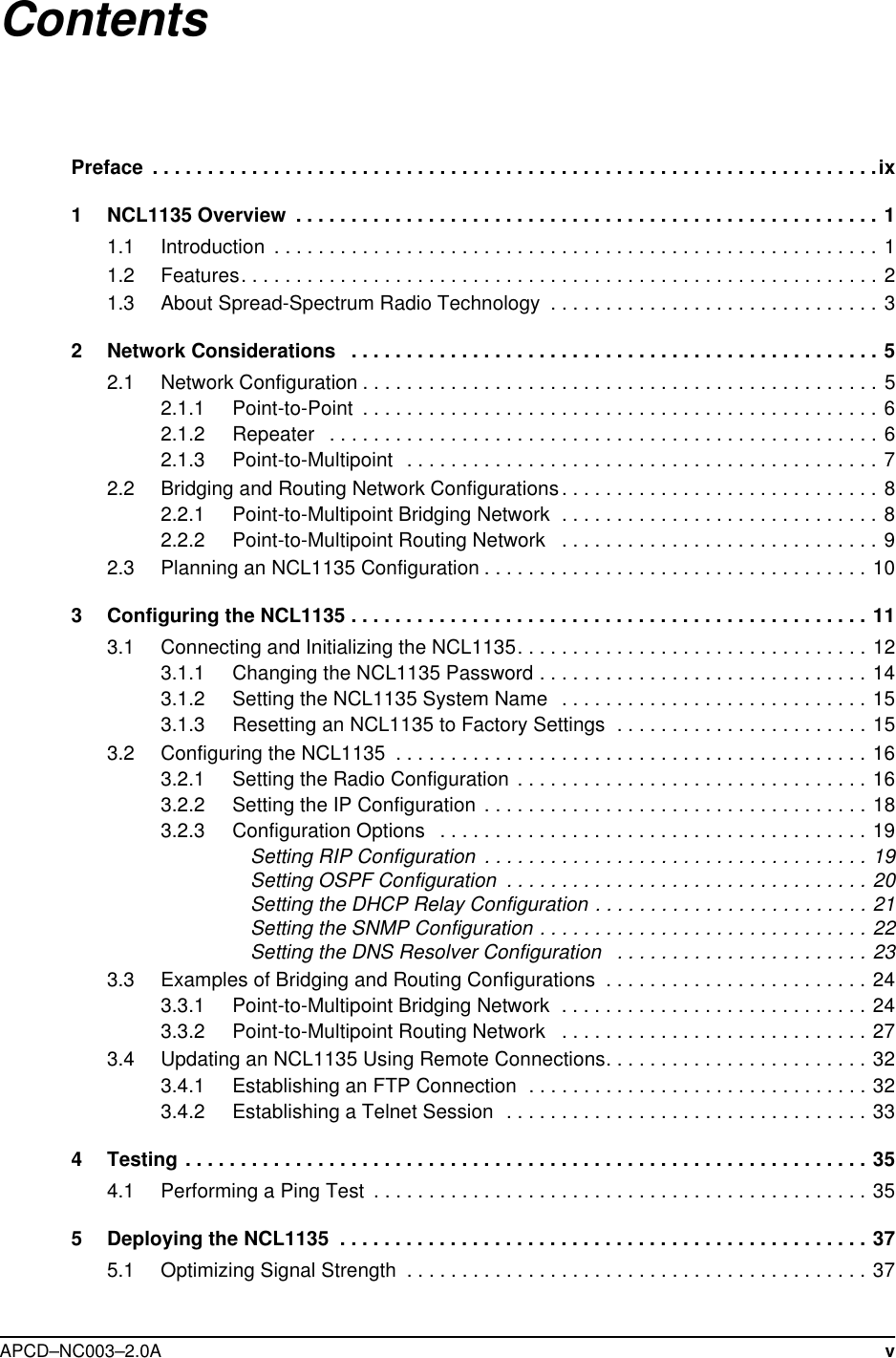
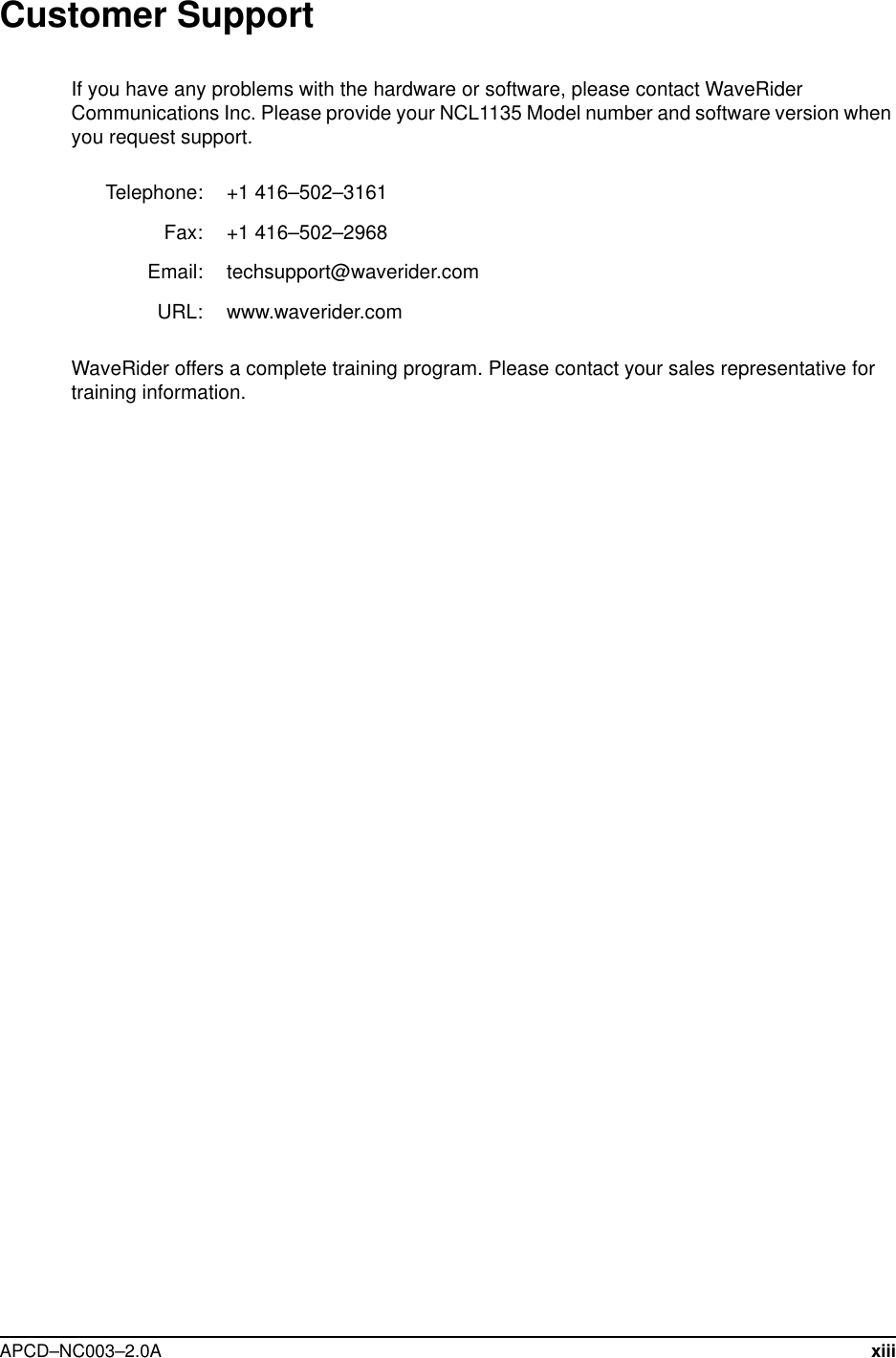


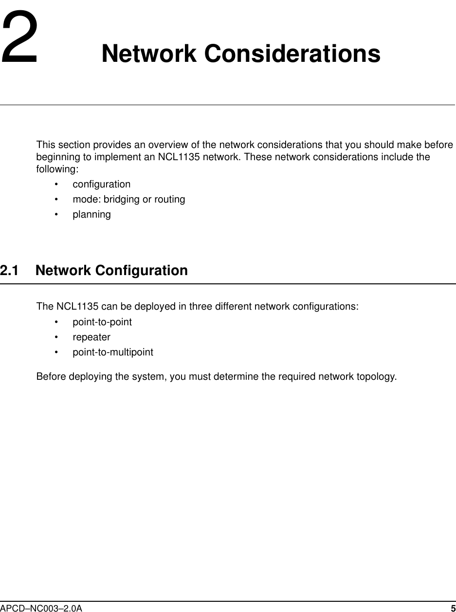
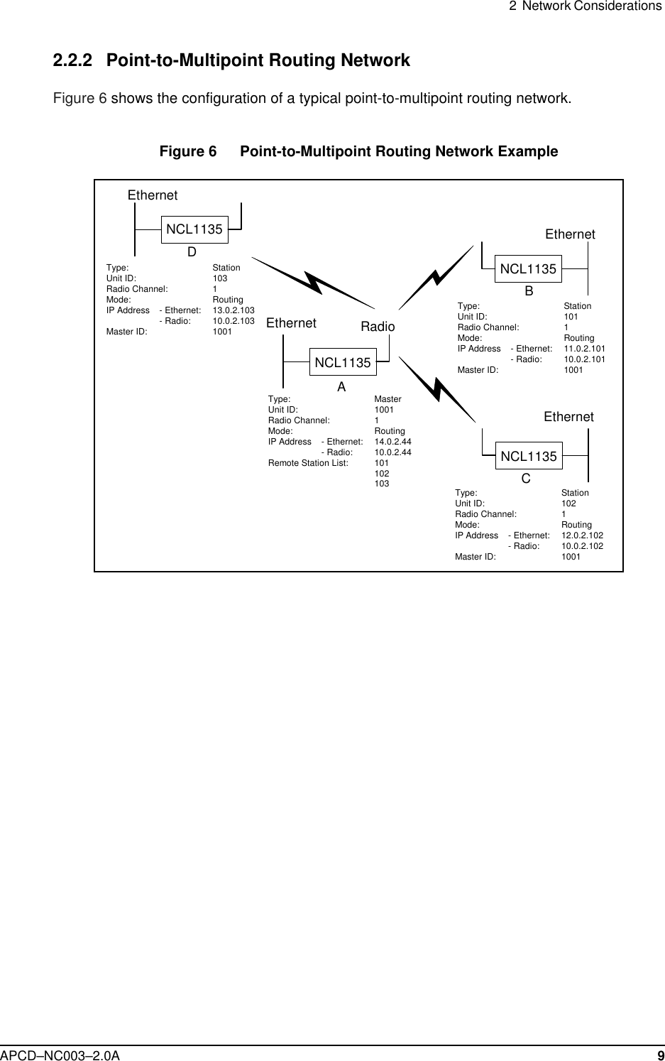
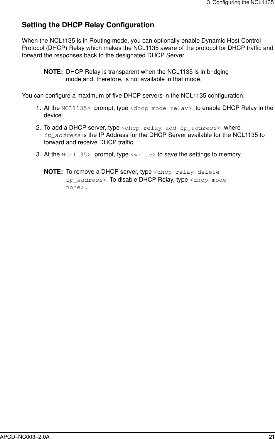
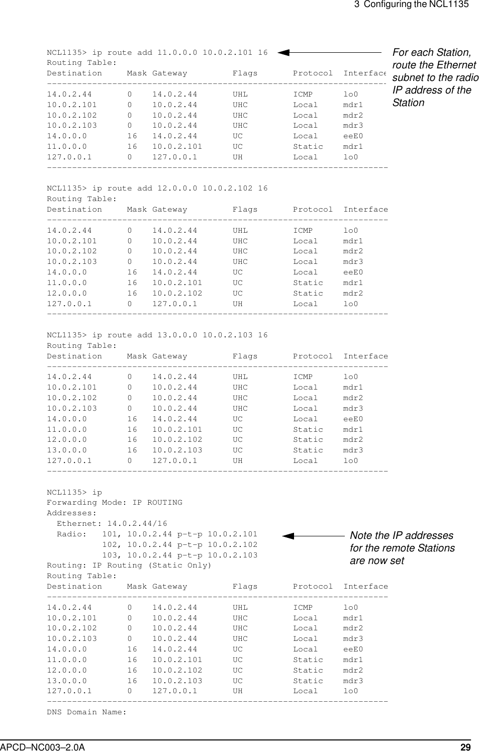
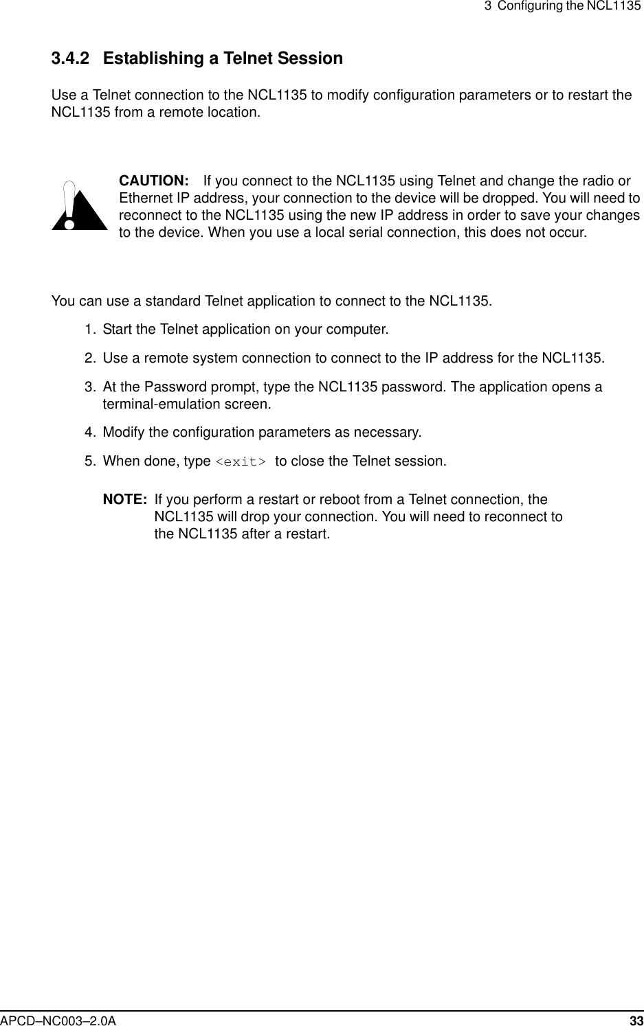

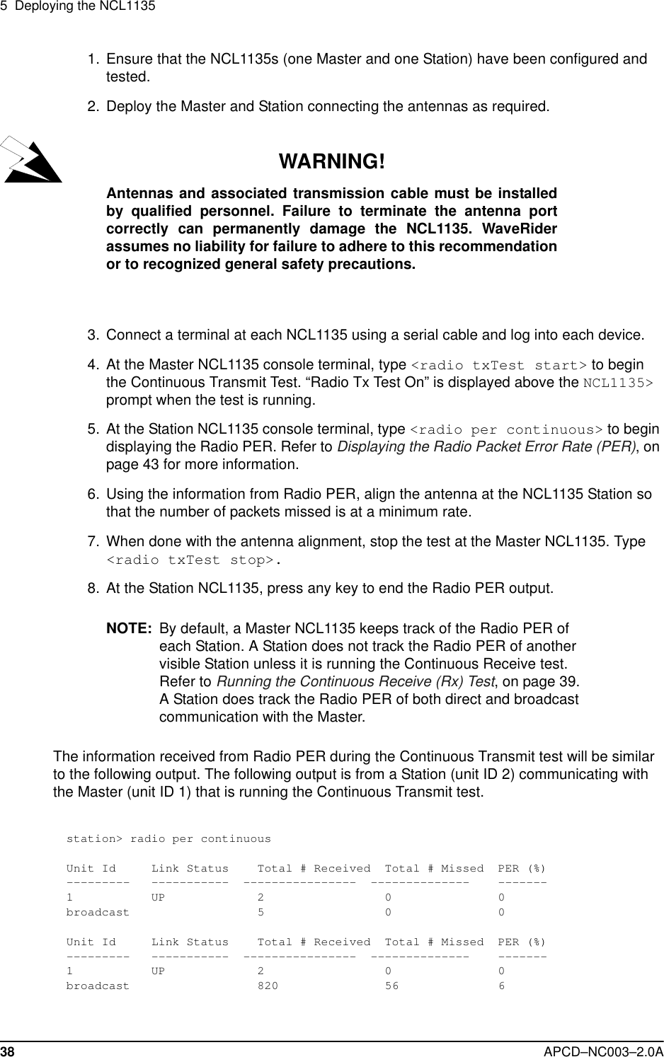
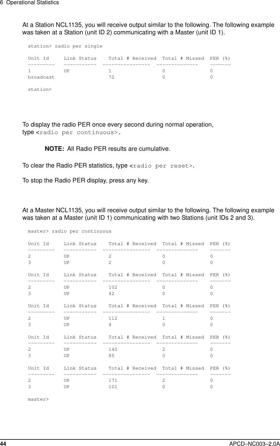
![5 Deploying the NCL113540 APCD–NC003–2.0A 5. Using the information from Radio PER, align the antenna at the NCL1135 Station so that the number of packets missed is at a minimum rate. 6. When done with the antenna alignment, press any key to stop the Radio PER display, then type <radio rxTest stop> to stop the test.NOTE: When the Continuous Receive test is stopped, the Master NCL1135 statistics, both direct and broadcast, remain in the Radio PER list and continue to be updated. If the Continuous Receive test is restarted, the statistics for the Master and broadcast will continue from where they left off. The Stations will start from zero again.The information received from Radio PER during the Continuous Receive test will be similar to the following output. The following output is from a Station (unit ID 2) communicating with the Master (unit ID 1) that is also transmitting to another Station (unit ID 3). station> radio rxtest startContinuous Rx test startedUnit Id Link Status Total # Received Total # Missed PER (%)--------- ----------- ---------------- -------------- -------1 UP 1 0 0broadcast 509 0 03 UP 1 0 0Unit Id Link Status Total # Received Total # Missed PER (%)--------- ----------- ---------------- -------------- -------1 UP 1 0 0broadcast 510 0 03 UP 1 0 0Unit Id Link Status Total # Received Total # Missed PER (%)--------- ----------- ---------------- -------------- -------1 UP 1 0 0broadcast 512 0 03 UP 1 0 0Unit Id Link Status Total # Received Total # Missed PER (%)--------- ----------- ---------------- -------------- -------1 UP 1 0 0broadcast 515 0 03 UP 1 0 0Unit Id Link Status Total # Received Total # Missed PER (%)--------- ----------- ---------------- -------------- -------1 UP 1 0 0broadcast 518 0 03 UP 1 0 0[Radio Rx Test On]station> radio rxtest stopstation>](https://usermanual.wiki/Vecima-Networks/WRM1151.Updated-Manual/User-Guide-114644-Page-54.png)
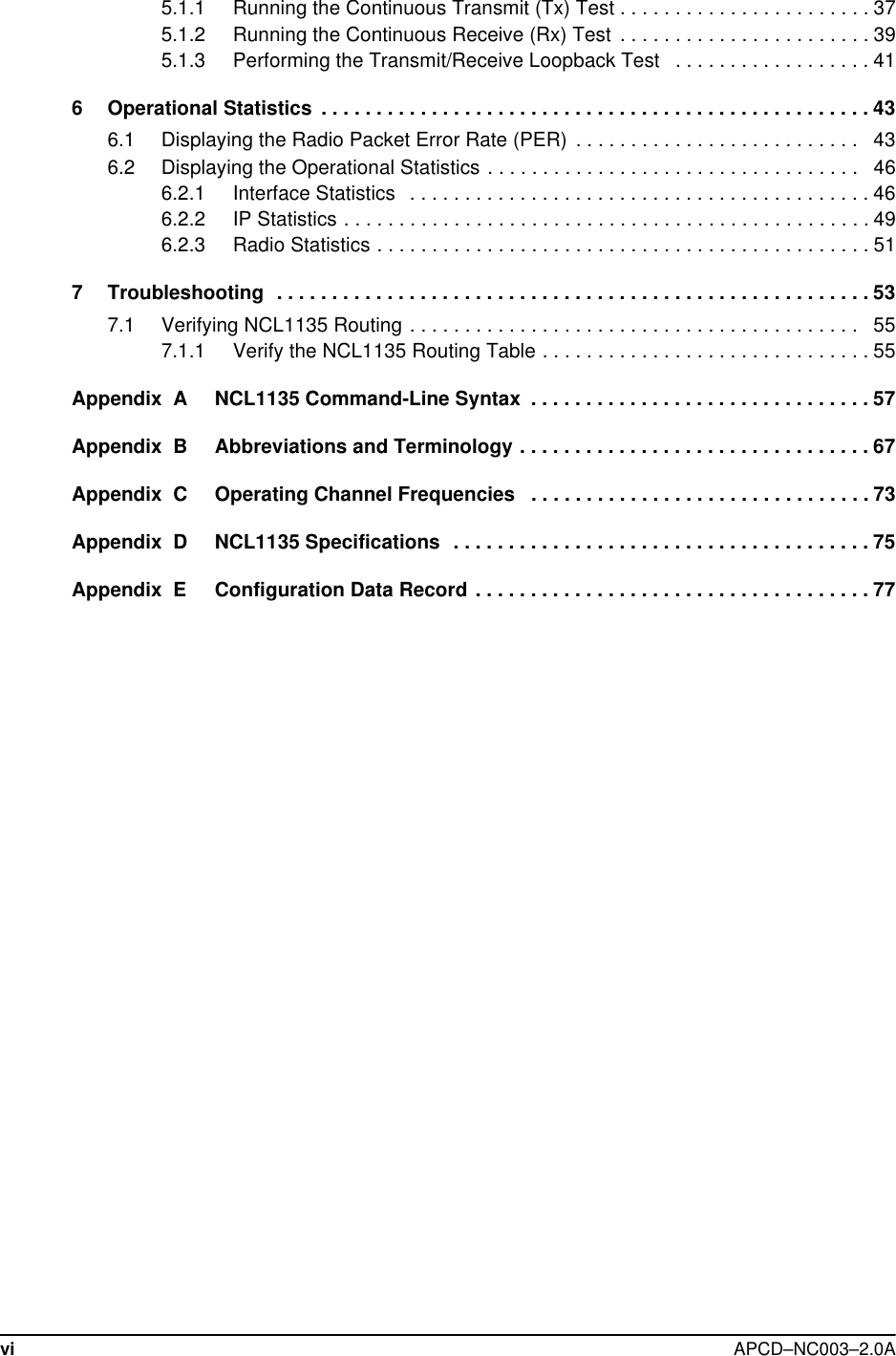
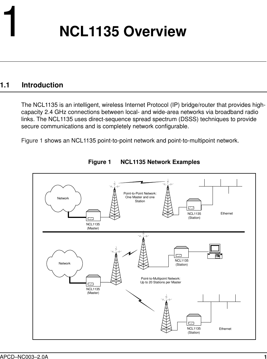
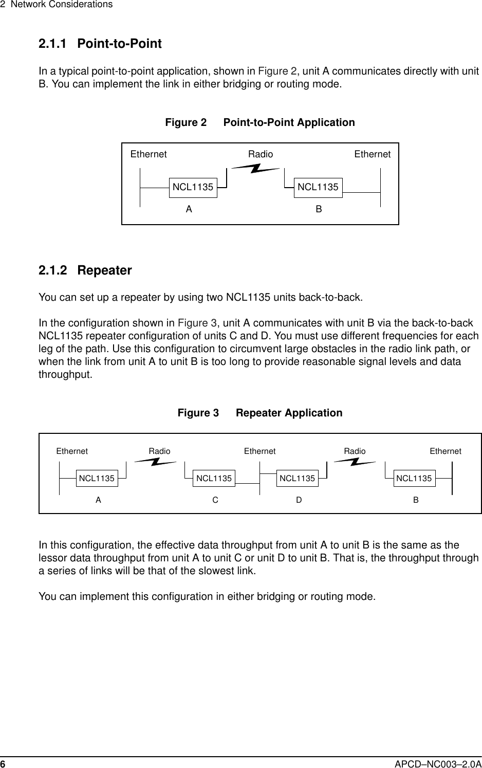
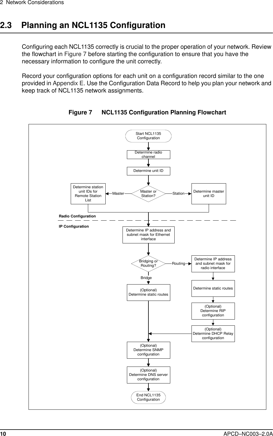
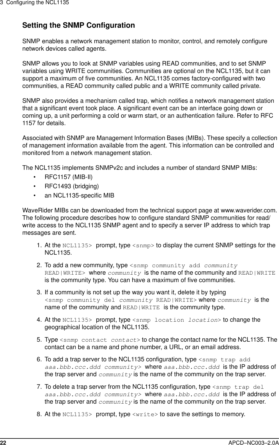
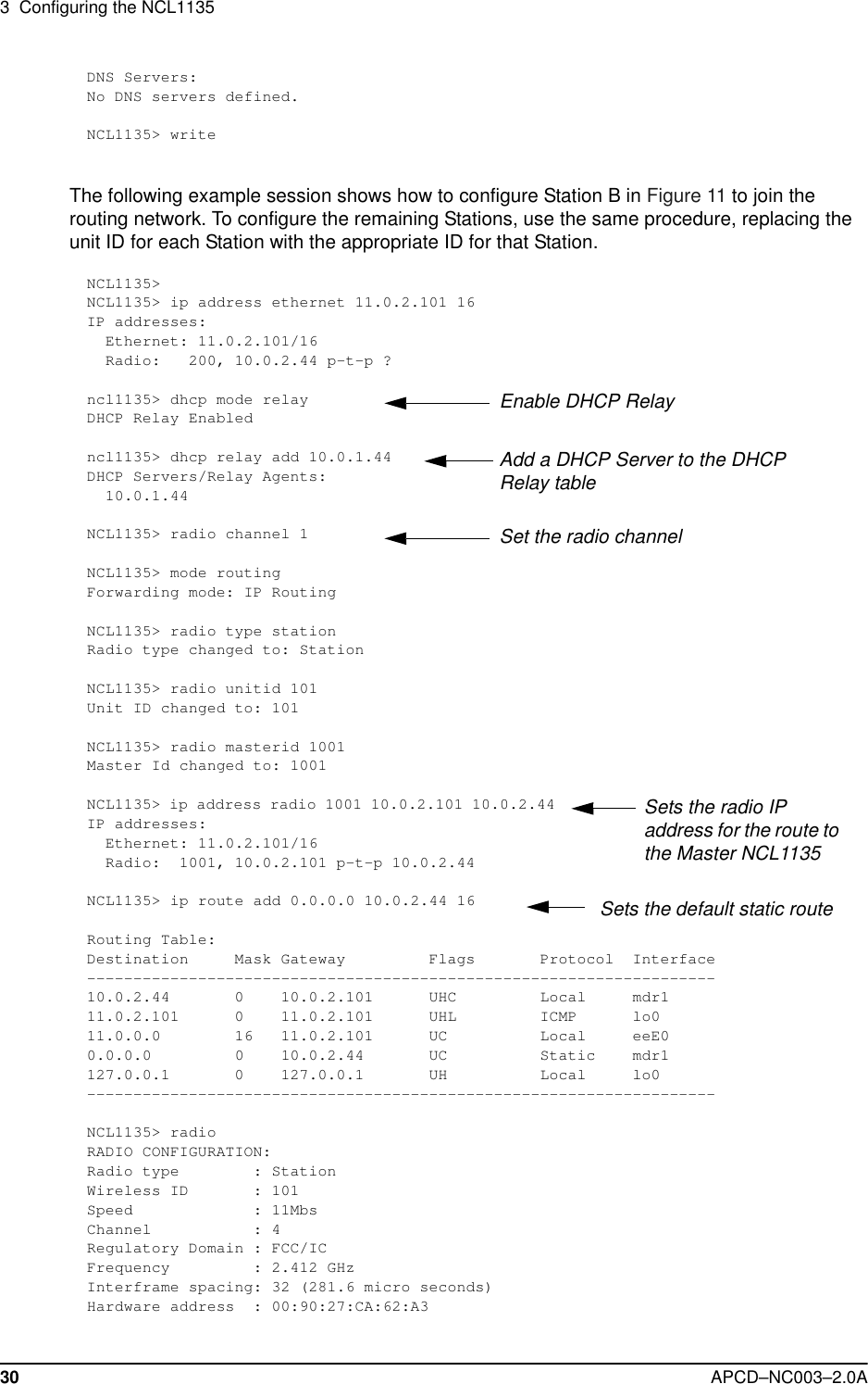
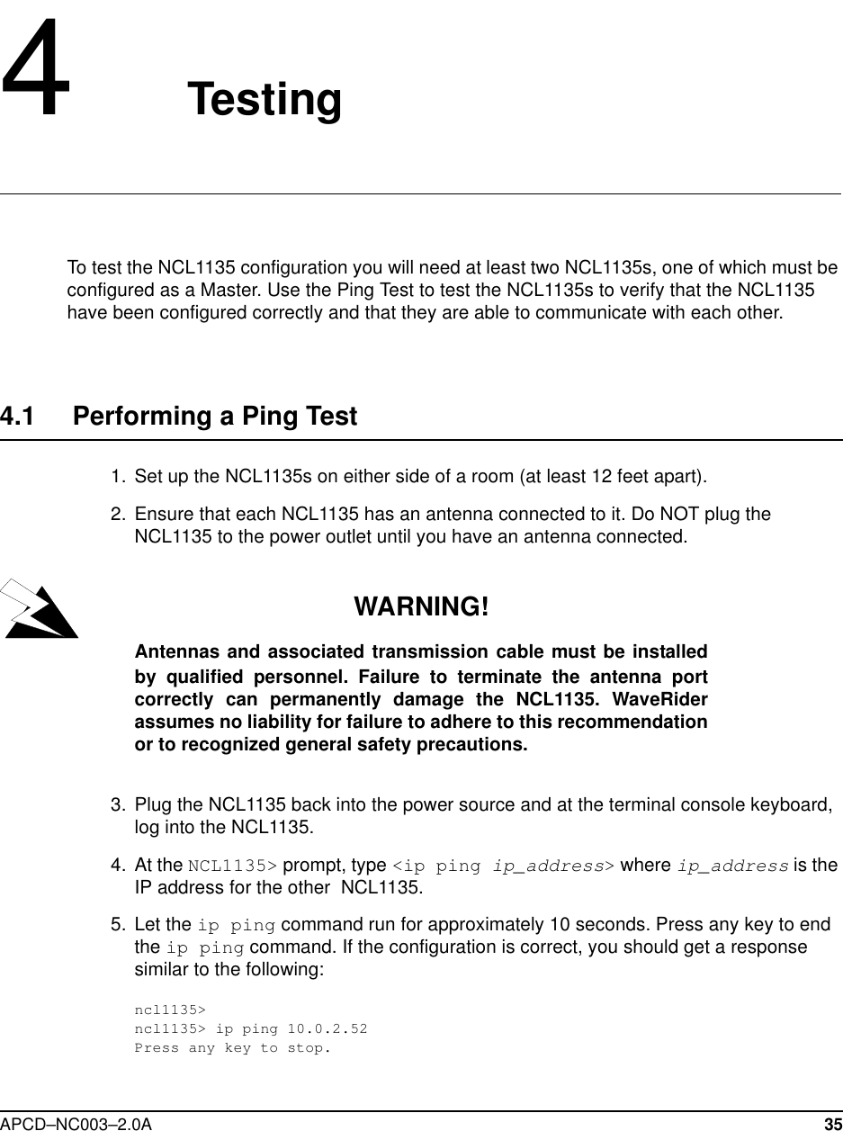
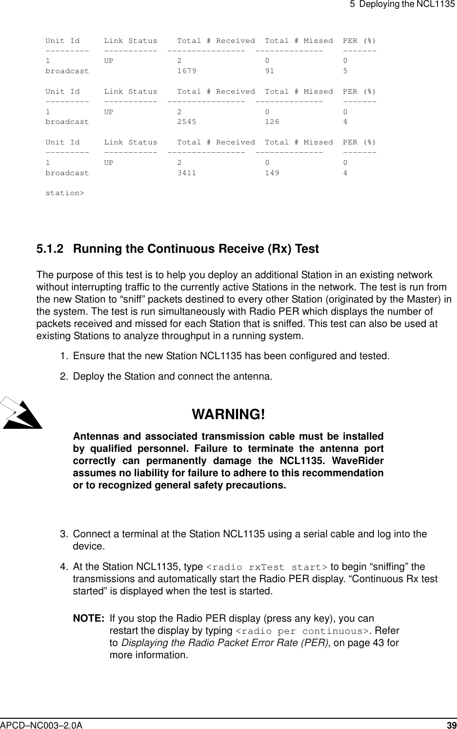
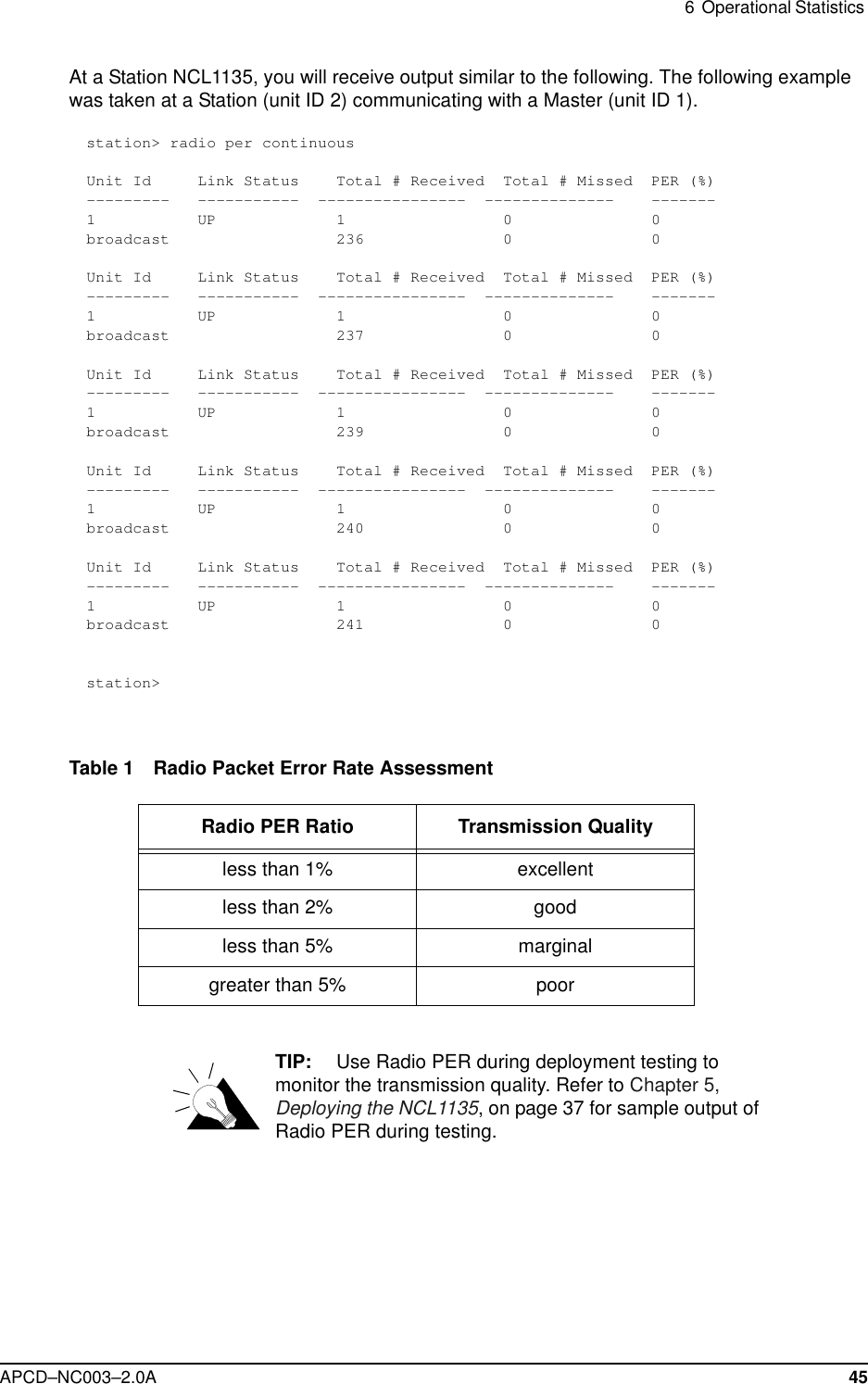
![5 Deploying the NCL113542 APCD–NC003–2.0AThe information received from Radio PER during the Transmit/Receive Loopback test will be similar to the following output. The following output is from a Master (unit ID 1) communicating with two Stations (unit IDs 2 and 3).master> radio txrx startTx/Rx test startedUnit Id Link Status Total # Received Total # Missed PER (%)--------- ----------- ---------------- -------------- -------2 UP 9 0 03 UP 5 0 0Unit Id Link Status Total # Received Total # Missed PER (%)--------- ----------- ---------------- -------------- -------2 UP 827 53 63 UP 820 56 6Unit Id Link Status Total # Received Total # Missed PER (%)--------- ----------- ---------------- -------------- -------2 UP 1689 85 43 UP 1679 91 5Unit Id Link Status Total # Received Total # Missed PER (%)--------- ----------- ---------------- -------------- -------2 UP 2566 109 43 UP 2545 126 4Unit Id Link Status Total # Received Total # Missed PER (%)--------- ----------- ---------------- -------------- -------2 UP 3423 141 33 UP 3411 149 4[Radio TxRx Test On]master> radio txrx stopmaster>](https://usermanual.wiki/Vecima-Networks/WRM1151.Updated-Manual/User-Guide-114644-Page-56.png)
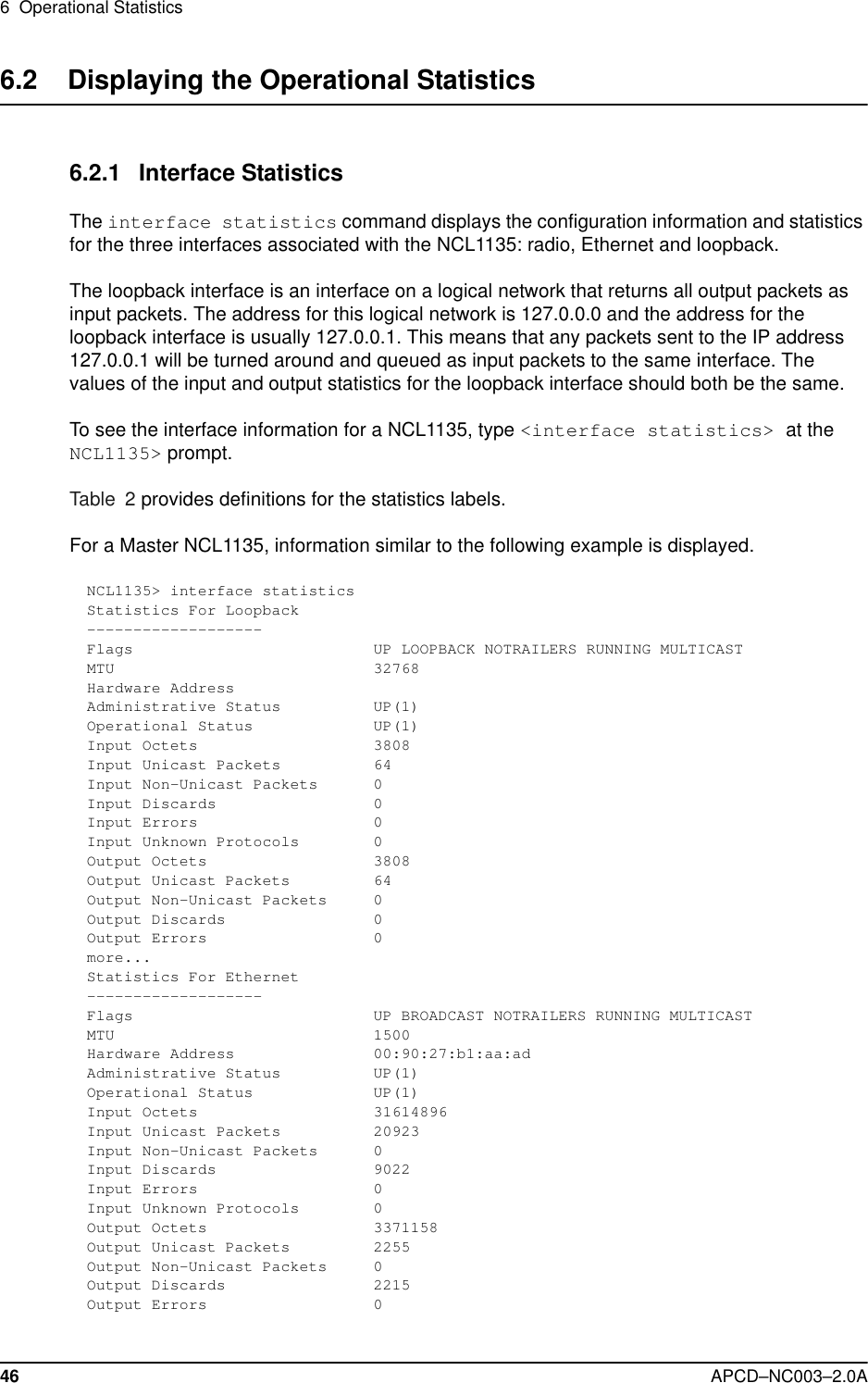


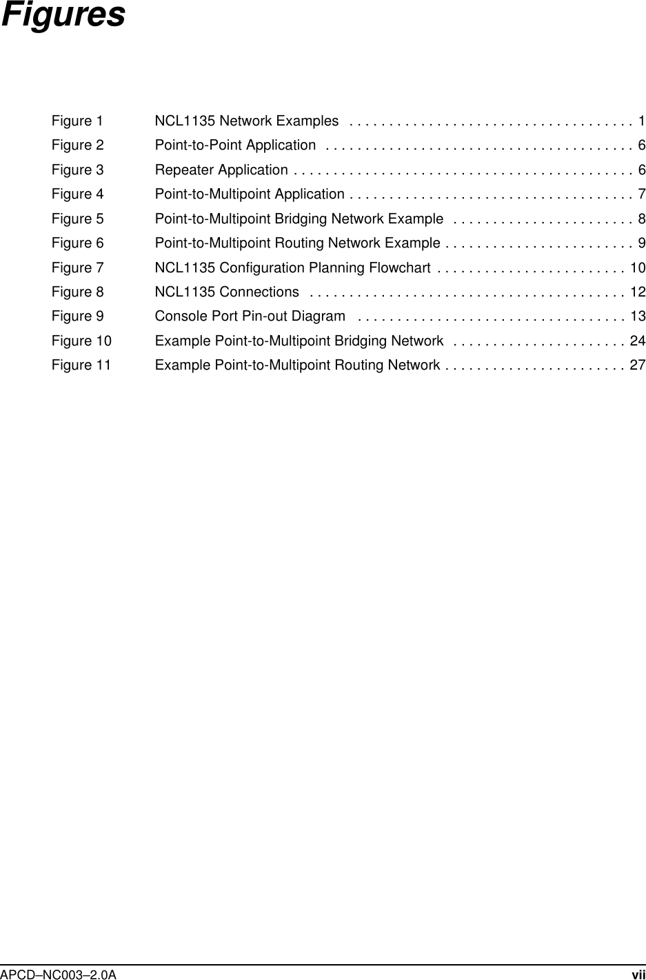
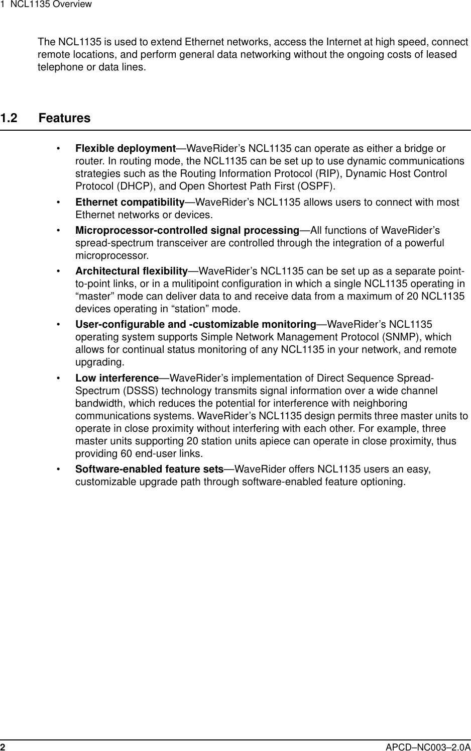
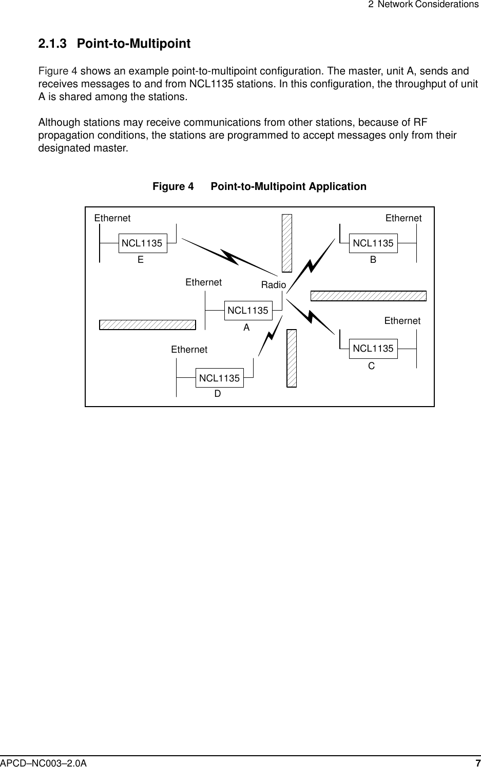
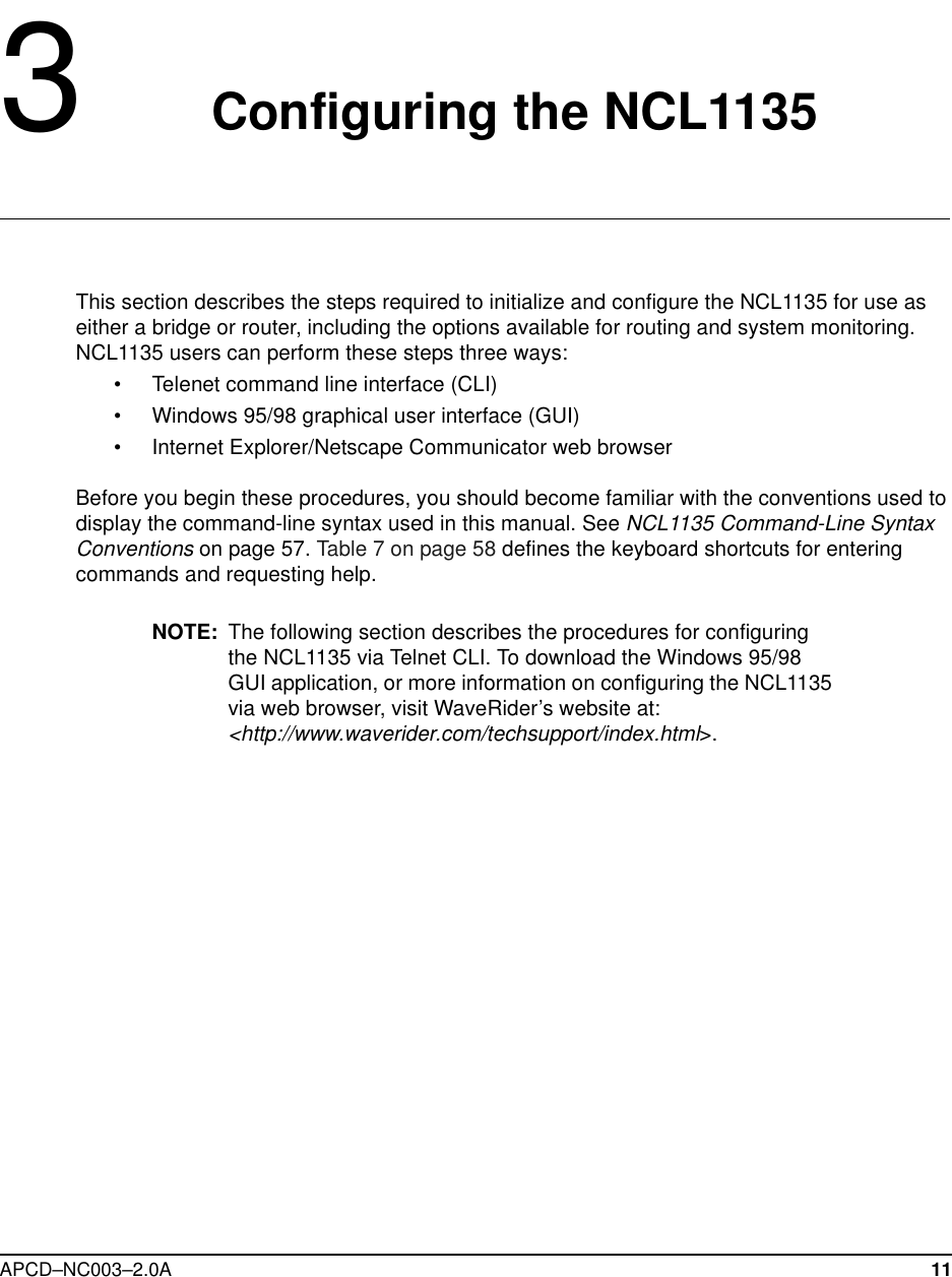
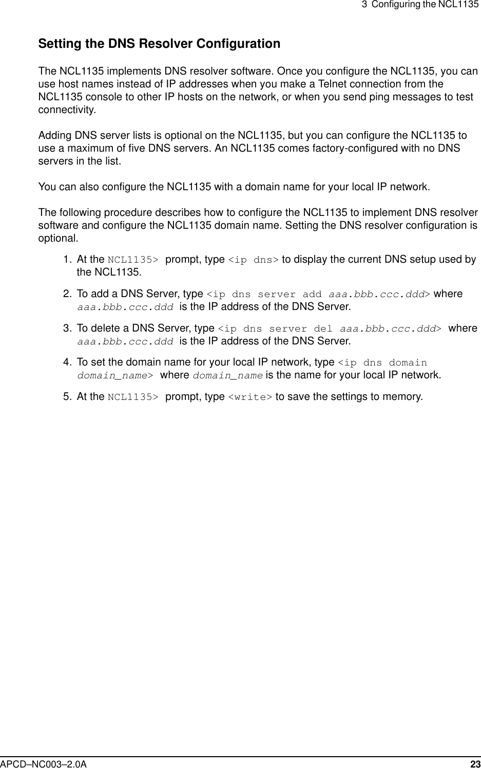
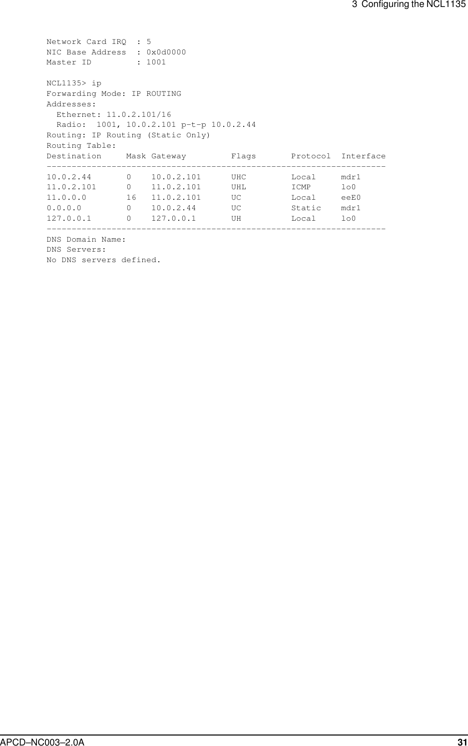
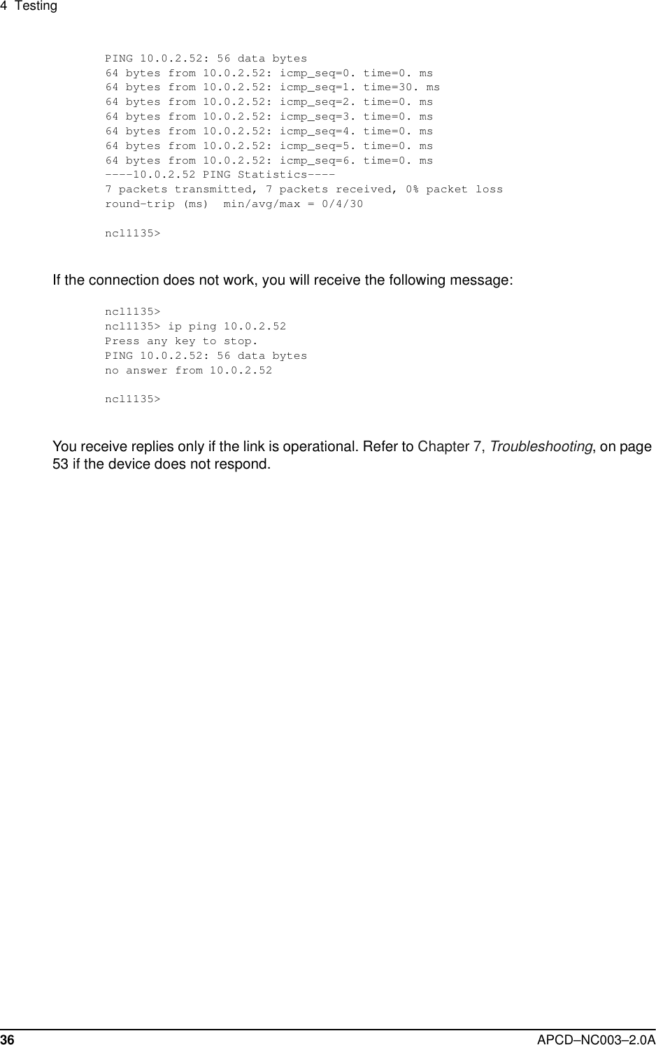
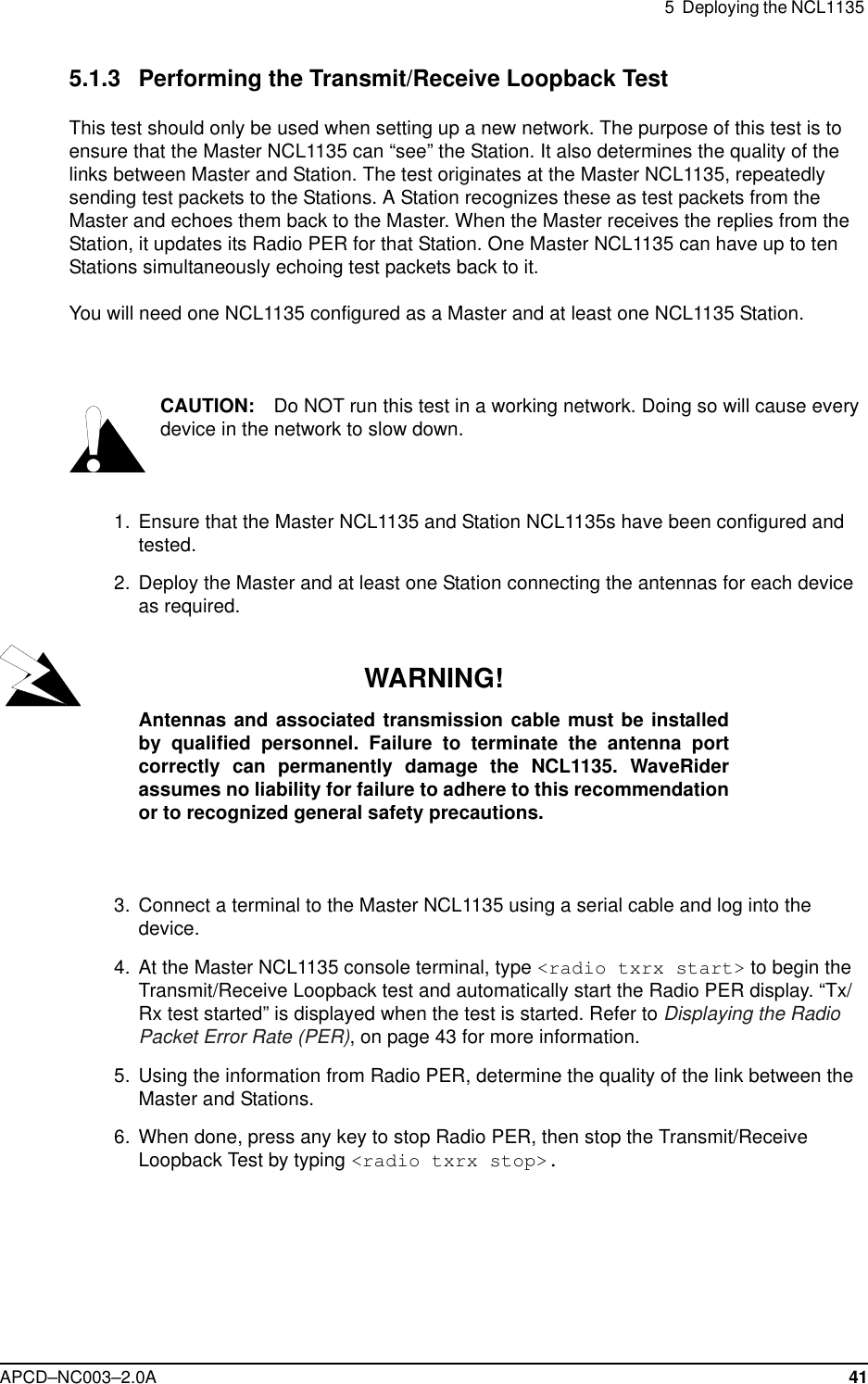
![APCD–NC003–2.0A 57Appendix A NCL1135 Command-Line SyntaxThe NCL1135 can be configured using the commands listed in Table 8.Table 6 shows the typographical conventions used to represent command-line syntax. Press ENTER after typing a command to execute the command.Table 7 provides a list of shortcuts and methods to get help on commands.Table 6 NCL1135 Command-Line Syntax ConventionsConvention Use Examples<monospaced font>Indicates that you must type the text inside the angle brackets, not the angle brackets. <ip route>ENTER Indicates a keyboard key press. A plus sign (+) indicates key combinations. For example, for CTRL+U, press and hold down the CTRL key, then press the U key.ENTERESCCTRL+Uitalic Specifies a variable name or other information that you must replace with a real name or value.ip address ethernet ipaddressbold characters Indicates the shortcut characters for a command. <radio channel> can also be typed as <ra ch> [ ] Indicates optional items. Do not type the brackets as part of the command. ip address [ethernet|radio] | Separates two mutually exclusive choices in a command. Type one choice and do not type the vertical bar.interface|if( ) Encloses a range of values from which you can choose a value. radio channel (1-15)](https://usermanual.wiki/Vecima-Networks/WRM1151.Updated-Manual/User-Guide-114644-Page-71.png)
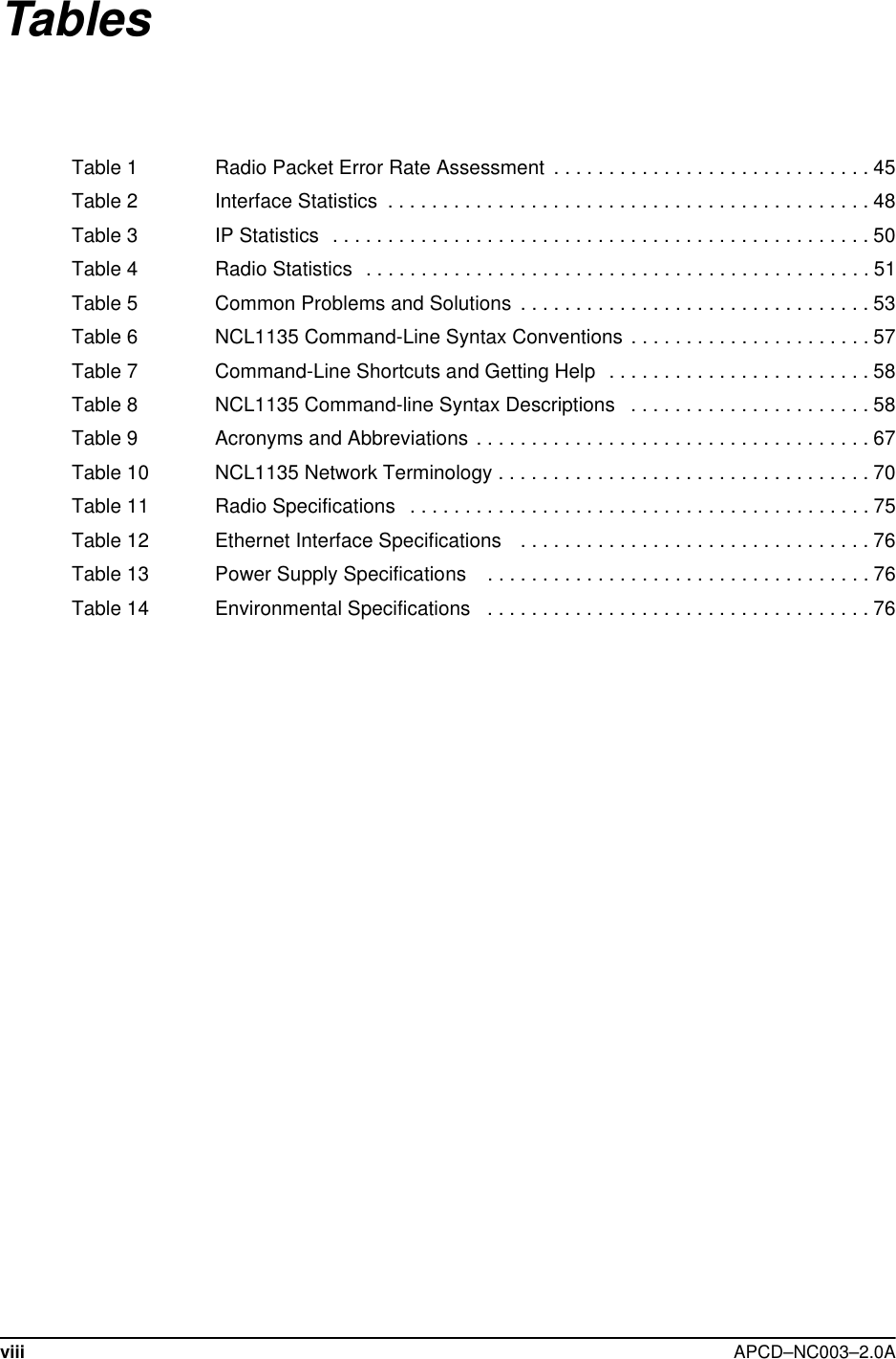
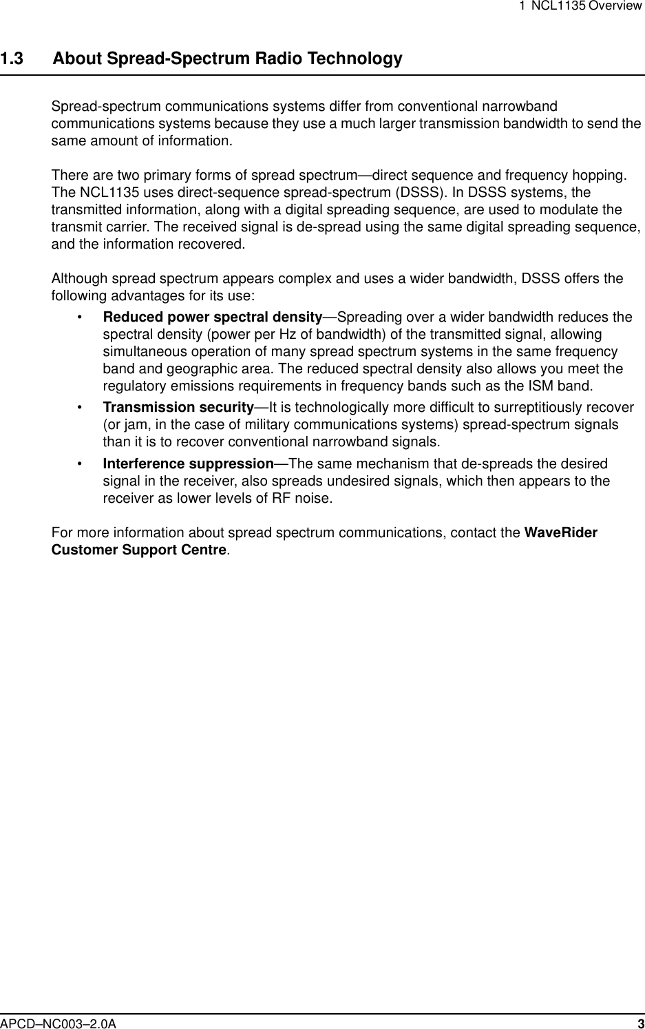
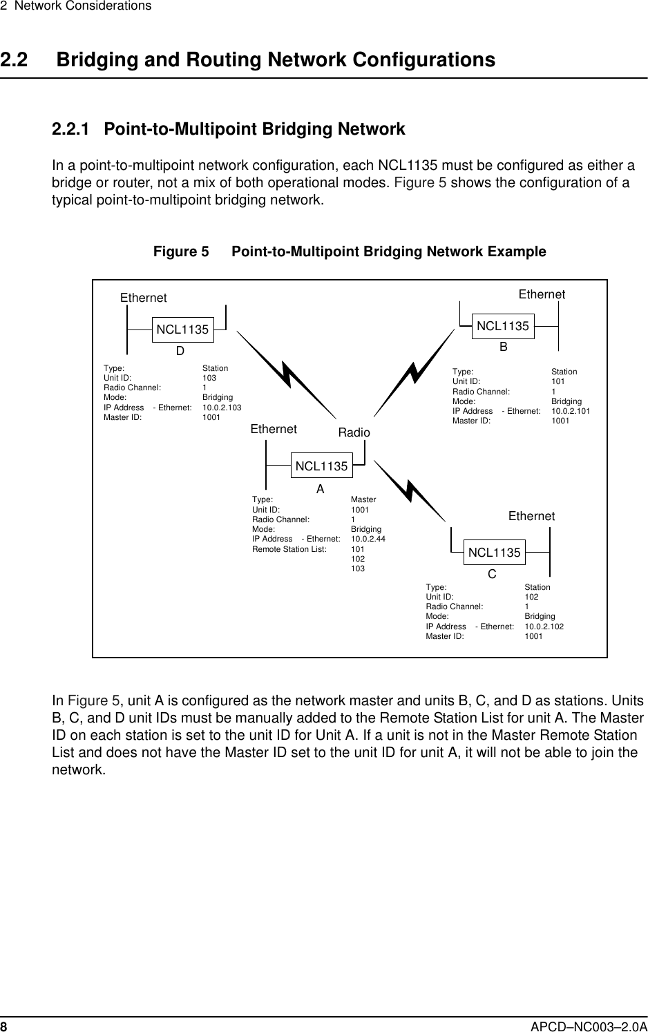
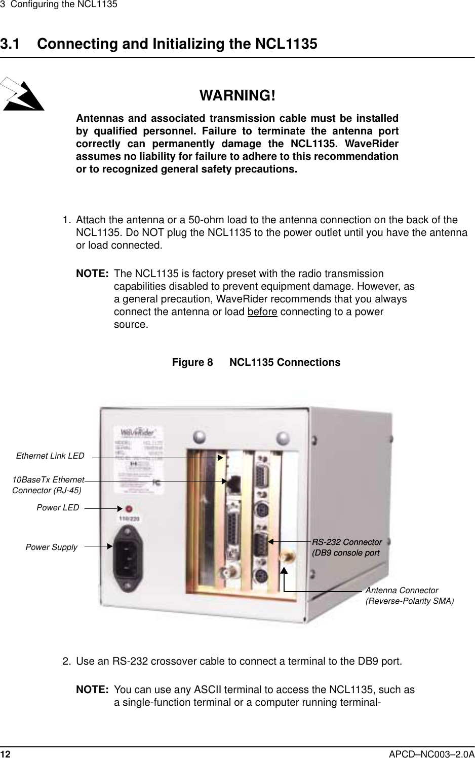
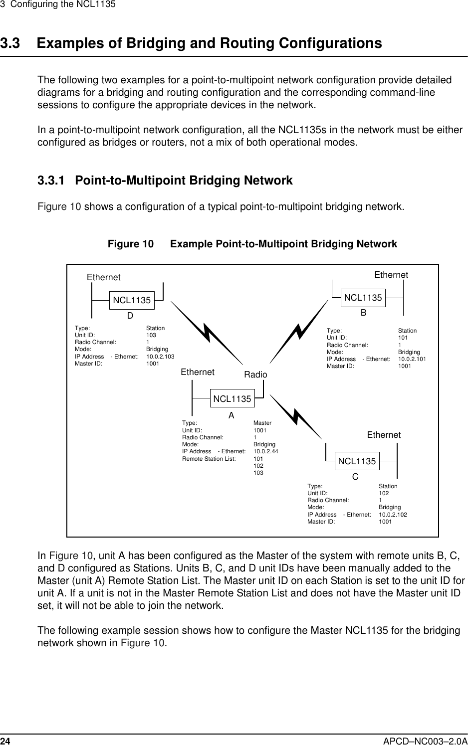
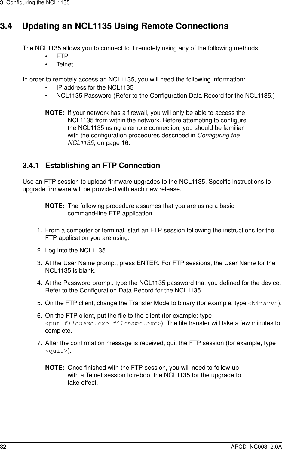
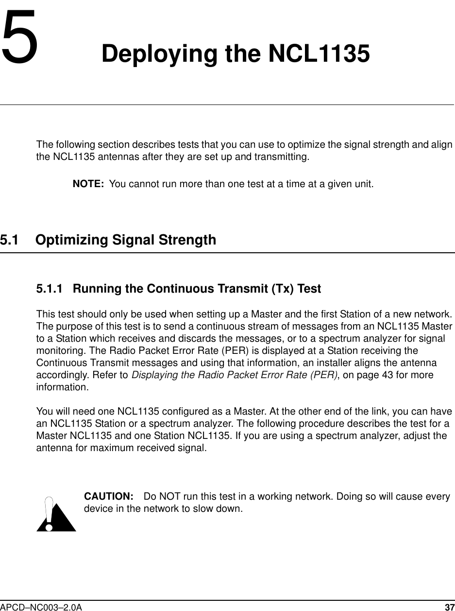
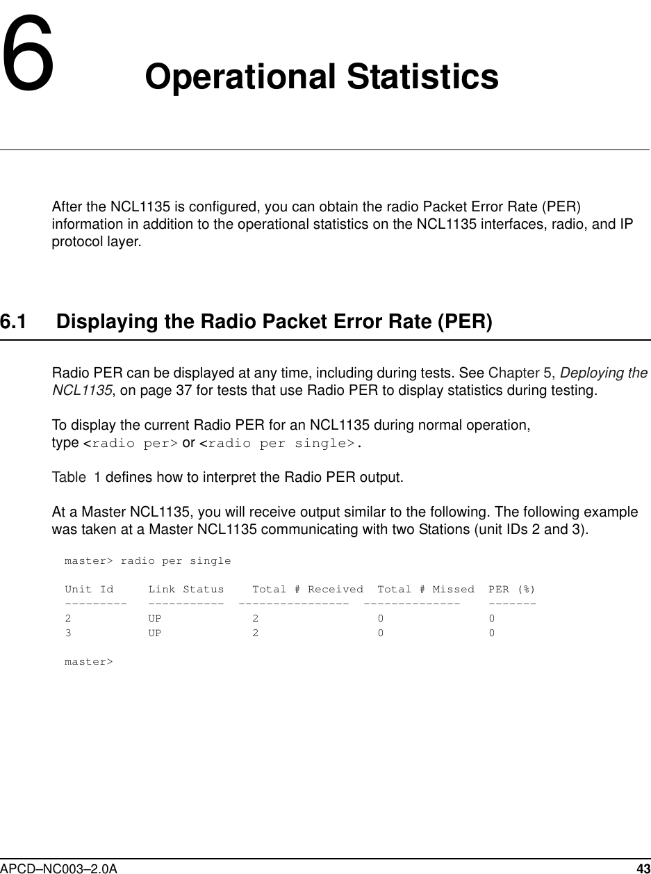
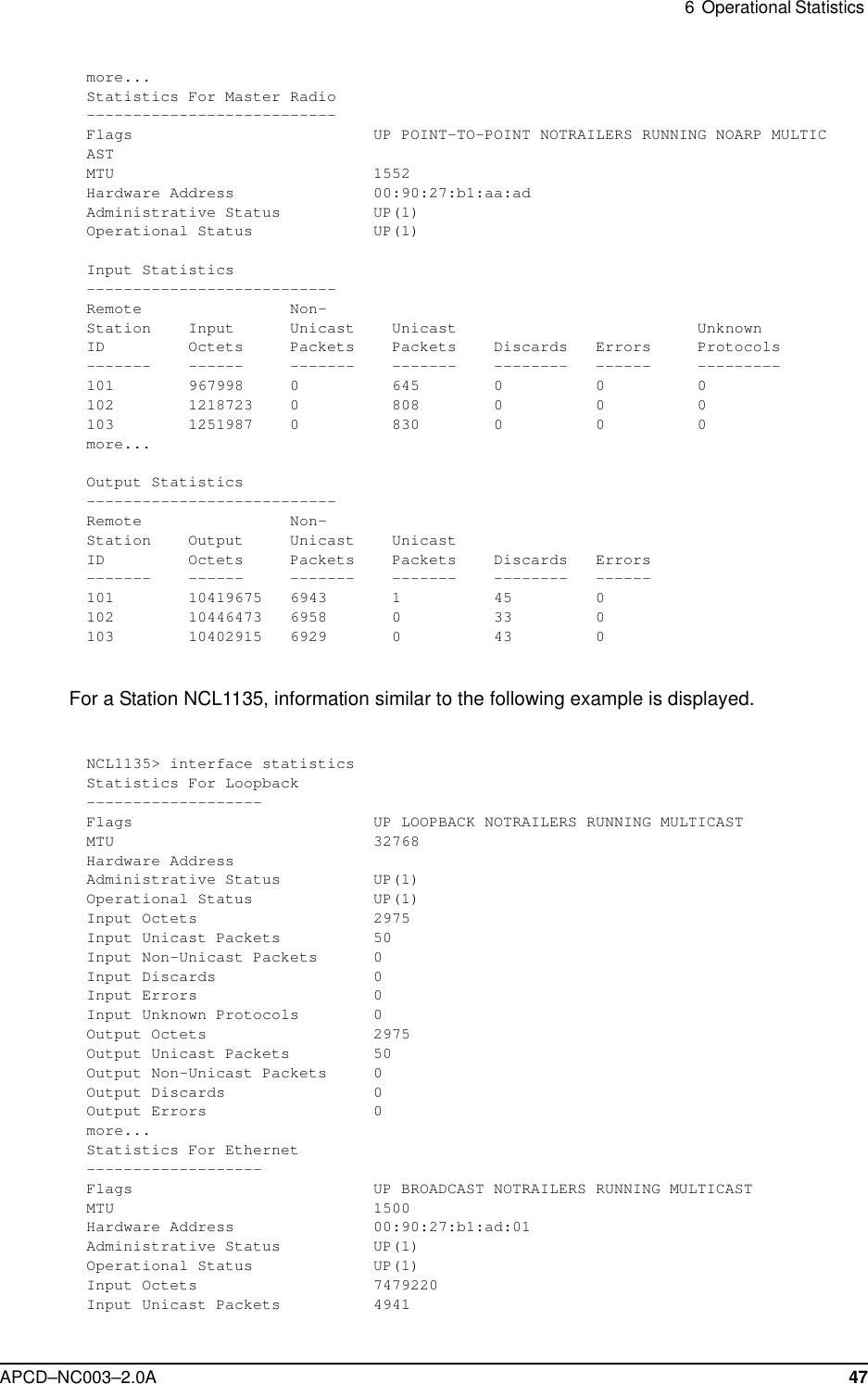
![58 APCD–NC003–2.0ATable 7 Command-Line Shortcuts and Getting HelpSubnet MasksWhere a command requires you to enter a subnet mask, you can do one of the following:•Enter it as a range, which is the number of bits (0-32 are valid) in the subnet mask.•Do not enter it, and let the NCL1135 decide what value to use. Note that the NCL1135 does not necessarily pick the correct subnet mask.Table 8 NCL1135 Command-line Syntax DescriptionsType To do this...?To display the names of the root commands.[command_name] ? To display the syntax for a command.help To display all the commands, their subcommands and the parameters and options for each command.help [command_name]To display the parameters and options for the command.!! To repeat the last command that was executed.ESC To cancel the command you are typing.Command Syntax Description arp Displays the Address Resolution Protocol (ARP) configuration information.arp flush Removes the temporary ARP table entries from the ARP table.arp add aaa.bbb.ccc.ddd aa:bb:cc:dd:ee:ffAdds an entry to the ARP table. aaa.bbb.ccc.ddd is the IP address of the entry that you want to add. aa:bb:cc:dd:ee:ff is the MAC address associated with the IP address.arp del aaa.bbb.ccc.ddd Deletes a specified entry from the ARP table. aaa.bbb.ccc.ddd is the IP address of the entry that you want to delete.bridge statistics Displays the bridge statistics (frames in, frames out, etc.). Only available in bridging mode.bridge table Displays the bridge table entries. Only available in bridging mode.bridge table flush Removes the learned entries from the bridge table. Only available in bridging mode.](https://usermanual.wiki/Vecima-Networks/WRM1151.Updated-Manual/User-Guide-114644-Page-72.png)
![APCD–NC003–2.0A 59bridge table timeout Sets the time-out value for entries in the bridge table. If the NCL1135 receives no packet from the specified entry’s address during the time-out period you set (for example, 15 s), then it clears the address from the table. Valid times are 10 to 1 000 000 s; the default is 300 s. Only available in bridging mode.dhcp mode [none|relay] Sets the NCL1135 to use Dynamic Host Configuration Protocol (DHCP).• none - disables DHCP Relay.• relay - enables DHCP Relay.Available only if the mode is set to routing.dhcp relay [add|delete ip_address]Adds or removes the IP address of a Dynamic Host Configuration Protocol (DHCP) server. Available only if the mode is set to routing and DHCP mode is set to Relay. interface|if statistics Displays configuration information and statistics for all interfaces.interface|if statistics ethernet|radio|loopbackDisplays configuration information and statistics for each interface: Ethernet, radio, or loopback.interface|if reset Resets the statistics for all interfaces.interface|if reset ethernet|radio|loopbackResets the statistics for the specified interface. ip Displays the IP configuration information.ip address Displays the IP addresses for the Ethernet and radio interface. In bridging mode, the IP address is for management purposes only. An IP address is not required to perform bridge functions. When in Bridging mode, if you assign an IP address to the NCL1135, you only need to assign it to the Ethernet interface, because the radio and Ethernet are considered as one interface.In routing mode, you must configure both addresses.ip address ethernet aaa.bbb.ccc.ddd [subnet mask]Changes the IP address for the Ethernet interface for routing or bridging. aaa.bbb.ccc.ddd is the IP address for the Ethernet interface and [subnet mask] is specified in either dotted decimal format or number of bits. Command Syntax Description](https://usermanual.wiki/Vecima-Networks/WRM1151.Updated-Manual/User-Guide-114644-Page-73.png)
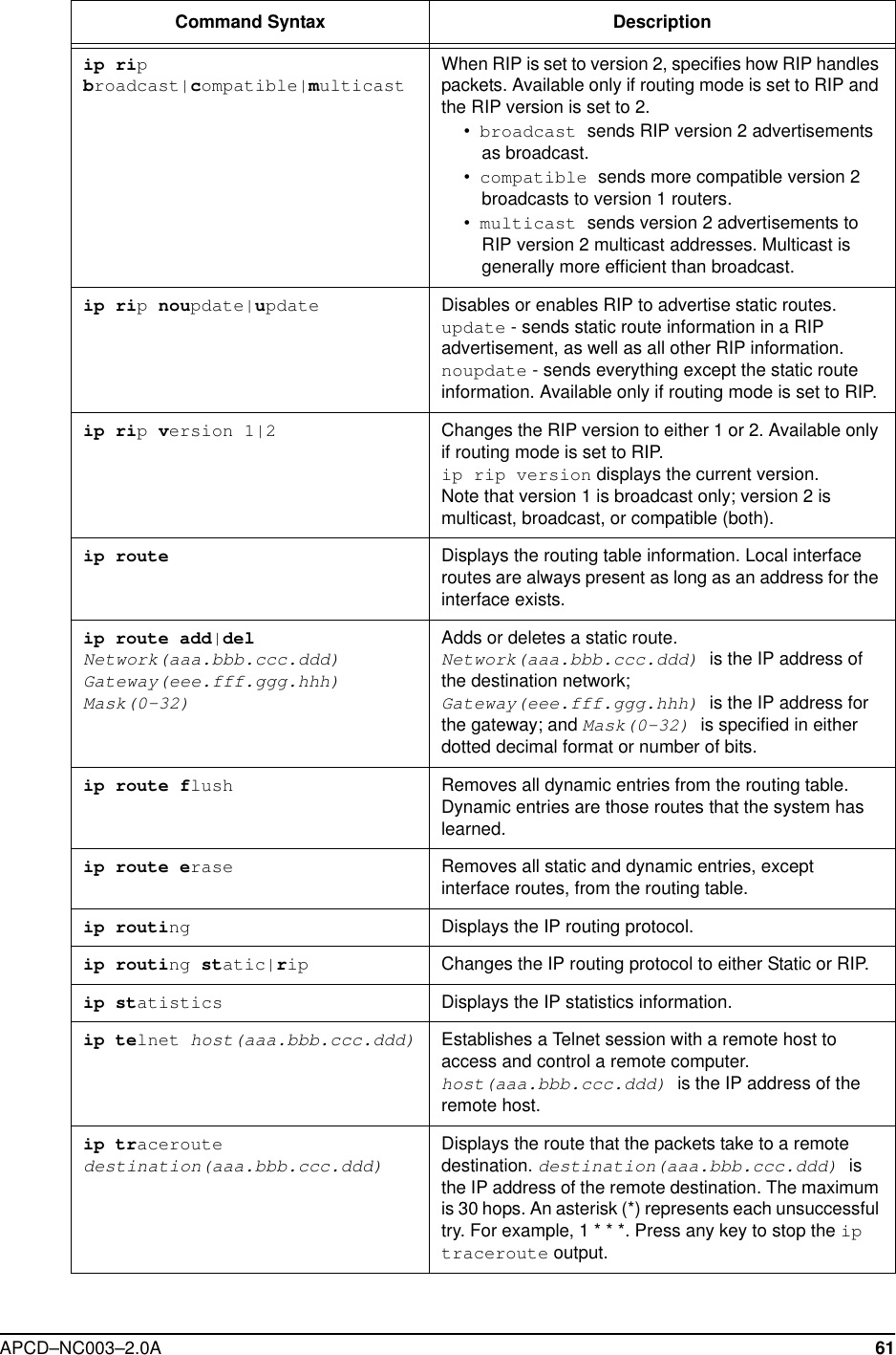
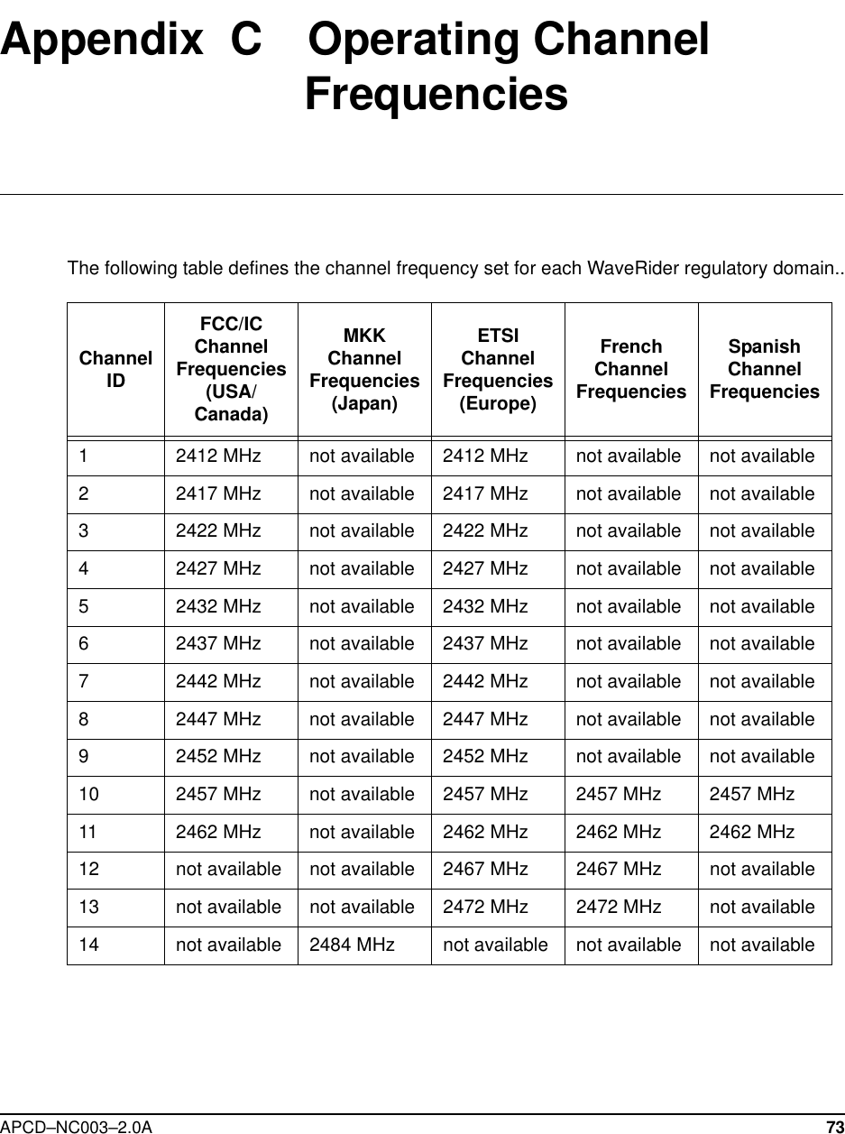
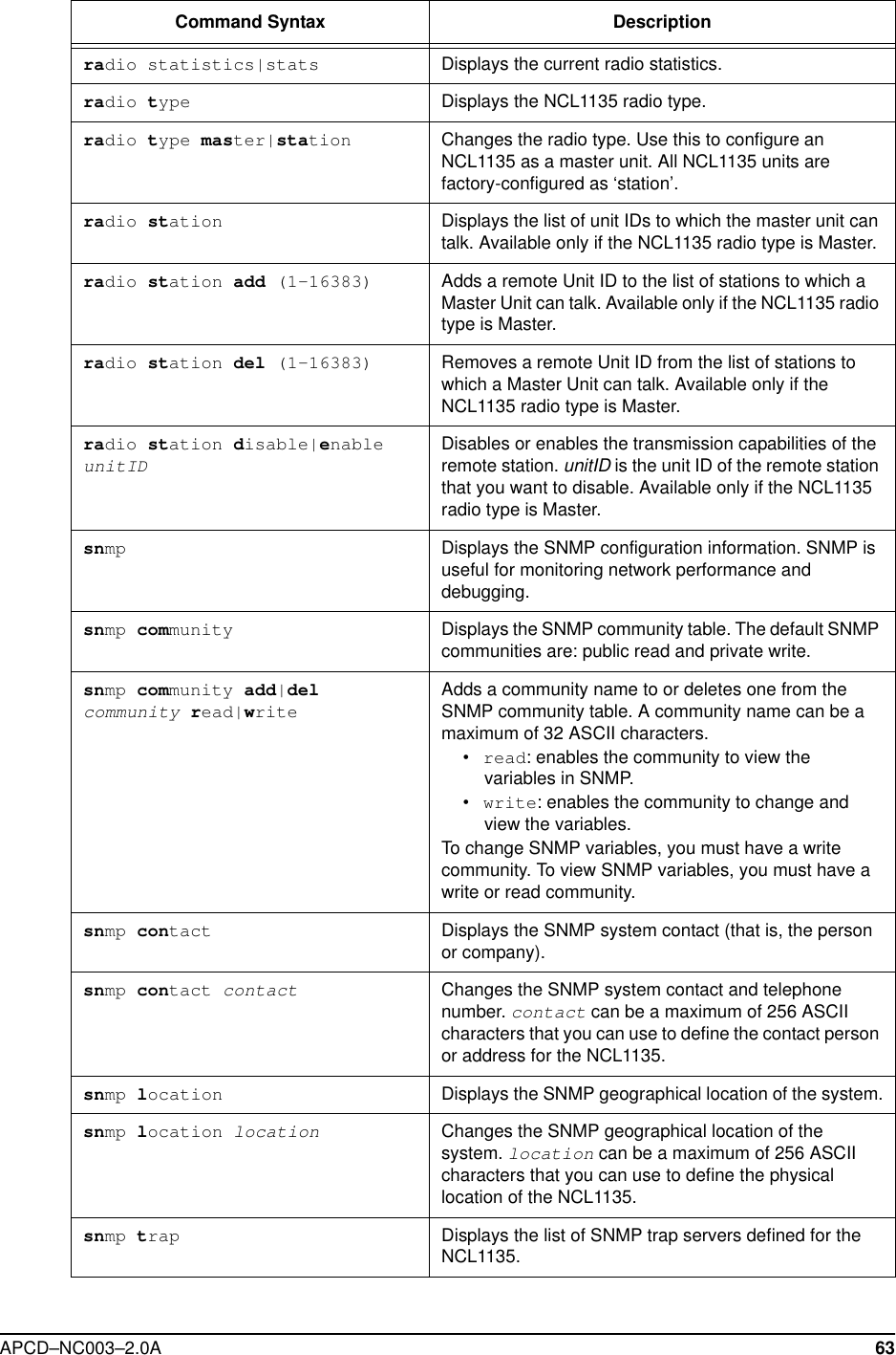
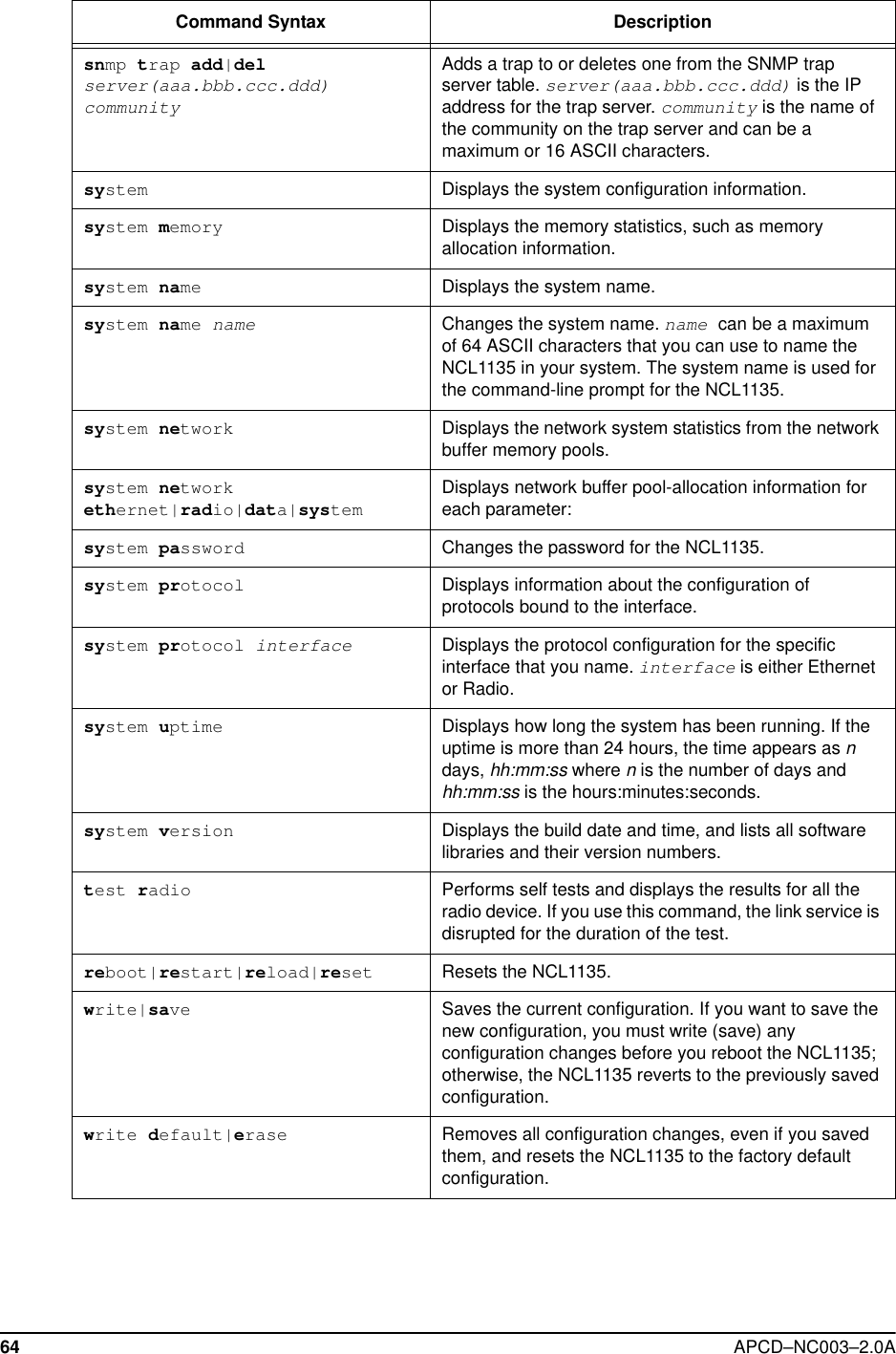
![62 APCD–NC003–2.0Amode Displays the forwarding mode: Bridging or IP Routing.mode bridging|routing Changes the forwarding mode. bridging: connects two networks on the same subnet (they have the same subnet address).routing: connects two networks on different subnets.radio Displays the radio configuration information.radio channel Displays the radio channel.radio channel (1–14) Changes the radio channel. radio disable|enable Disables or enables the NCL1135 radio transmission capabilities. The NCL1135 is factory-configured as disabled to prevent accidental damage should it be powered up without an antenna or load connected.radio per [single|continuous|reset]Displays or resets the cumulative radio packet error rate statistics to the screen. This command is available during tests and normal operation.•single displays the current statistics.•continuous displays the statistics every one second.•reset resets the calculations.radio rxtest start|stopStarts and stops the Radio Continuous Receive Test. When you start this test, the Radio PER display is also automatically started. Available only at the Station NCL1135. Use this test to deploy a new Station NCL1135 in an existing network.radio txtest start|stopStarts and stops the Radio Continuous Transmit Test. Available only at the Master NCL1135. Use this test to set up a Master and Station for a new network.radio txrx start|stopStarts and stops the Radio Transmit/Receive Loopback Test. When you start this test, the Radio PER display is also automatically started. Available only at the Master NCL1135. Use this test for a new installation only.radio reset Forces the NCL1135 to reset. If you reset the NCL1135 radio instead of shutting down, the statistics are not lost. If you use this command, the link service is disrupted for the duration of the test.radio unitid Displays the NCL1135 unit ID.radio unitid (1–16383) Changes the NCL1135 unit ID. An NCL1135 unit ID is a unique number between 1 and 16383.radio masterID Displays the Master Unit ID to which the NCL1135 belongs. Available only if the NCL1135 radio type is Station.radio masterID (1–16383) Changes the Master Unit ID to which the NCL1135 belongs. Available only if the NCL1135 radio type is Station.Command Syntax Description](https://usermanual.wiki/Vecima-Networks/WRM1151.Updated-Manual/User-Guide-114644-Page-76.png)
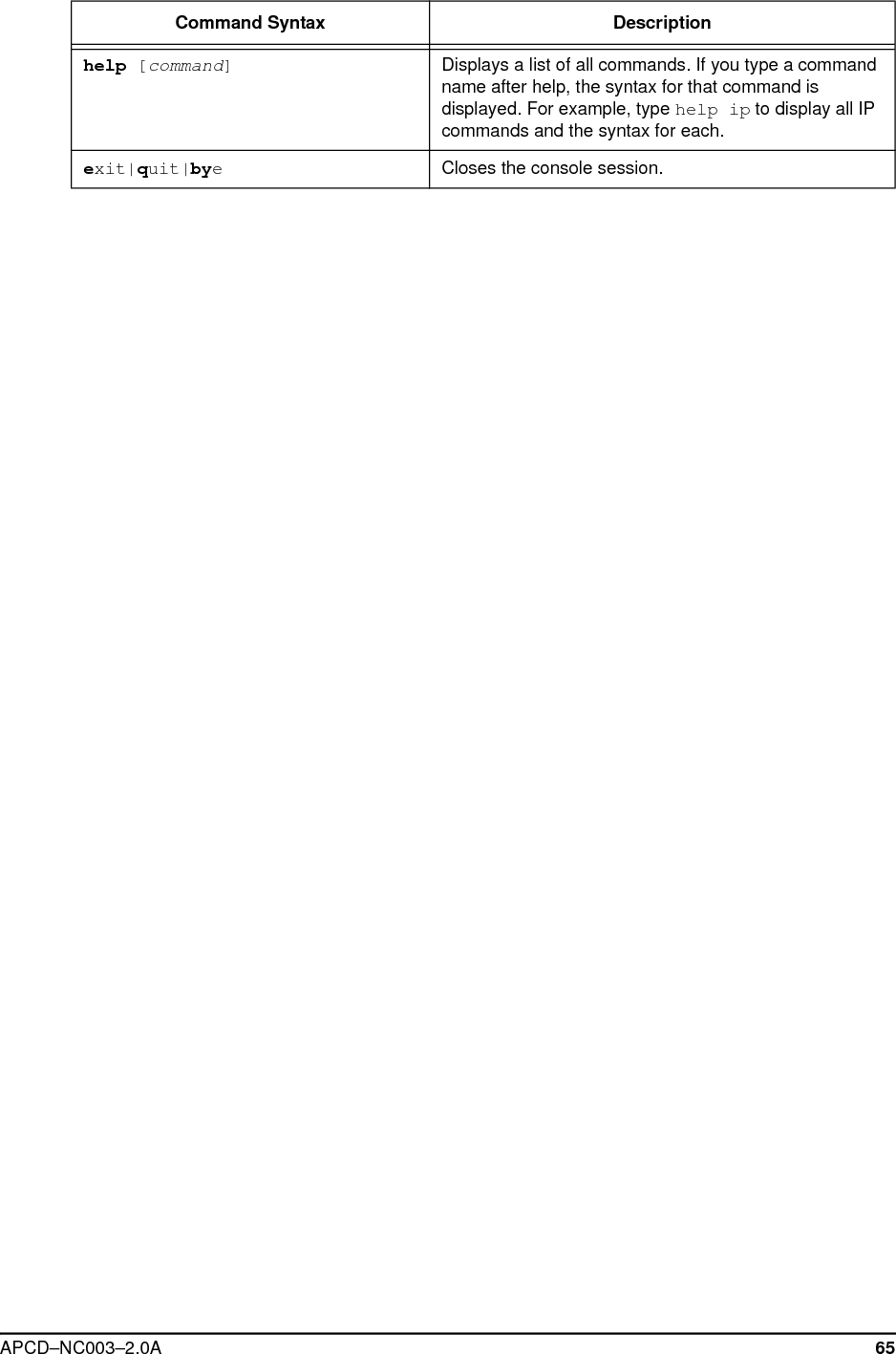
![APCD–NC003–2.0A 65help [command]Displays a list of all commands. If you type a command name after help, the syntax for that command is displayed. For example, type help ip to display all IP commands and the syntax for each.exit|quit|byeCloses the console session.Command Syntax Description](https://usermanual.wiki/Vecima-Networks/WRM1151.Updated-Manual/User-Guide-114644-Page-79.png)