Vecima Networks WRM1151 2.4GHz 6 Channel DSSS Transceiver User Manual
Vecima Networks Inc. 2.4GHz 6 Channel DSSS Transceiver
Contents
- 1. Updated Manual
- 2. Users Manual
Updated Manual

NCL1135 User Manual
Version 2.0
WaveRider Communications Inc.
Software License Agreement
This is a legal agreement between you (either an individual or an entity) and WaveRider Communications Inc. for the use
of WaveRider computer software, hereinafter the “LICENSED SOFTWARE”.
By using the LICENSED SOFTWARE installed in this product, you acknowledge that you have read this license
agreement, understand it, and agree to be bound by its terms. You further agree that it is the full and complete
agreement between you and WaveRider Communications Inc., superseding all prior written or verbal agreements of any
kind related to the LICENSED SOFTWARE. If you do not understand or do not agree to the terms of this agreement, you
must cease using the LICENSED SOFTWARE immediately.
1 GRANT OF LICENSE—This License Agreement permits you to use one copy of the LICENSED SOFTWARE.
2. COPYRIGHT—The LICENSED SOFTWARE is owned by WaveRider Communications Inc. and is protected by
copyright laws and international treaty provisions; therefore, you must treat the LICENSED SOFTWARE like
any other copyrighted material (e.g., a book or magazine). You may not copy the written materials
accompanying the LICENSED SOFTWARE.
3. OTHER RESTRICTIONS—You may not rent or lease the LICENSED SOFTWARE. You may not reverse
engineer, decompile, or disassemble the LICENSED SOFTWARE.
4. LIMITED WARRANTY—The LICENSED SOFTWARE is provided “as is” without any warranty of any kind,
either expressed or implied, including, but not limited to, the implied warranties of merchantability and fitness
for a particular purpose. The entire risk as to the quality and performance of the LICENSED SOFTWARE is
with you, the licensee. If the LICENSED SOFTWARE is defective, you assume the risk and liability for the
entire cost of all necessary repair, service, or correction.
Some states/jurisdictions do not allow the exclusion of implied warranties, so the above exclusion
may not apply to you. This warranty gives you specific legal rights, and you may have other rights,
which vary from state/jurisdiction to state/jurisdiction.
WaveRider Communications Inc. does not warrant that the functions contained in the LICENSED
SOFTWARE will meet your requirements, or that the operation of the LICENSED SOFTWARE will be
error-free or uninterrupted.
5. NO OTHER WARRANTIES—To the maximum extent permitted by applicable law, WaveRider Communications
Inc. disclaims all other warranties, either express or implied, including, but not limited to, the implied warranties
of merchantability and fitness for a particular purpose, with regard to the LICENSED SOFTWARE and the
accompanying written materials.
6. NO LIABILITY FOR CONSEQUENTIAL DAMAGES—To the maximum extent permitted by applicable law, in
no event shall WaveRider Communications Inc. or its suppliers be liable for any damages whatsoever
(including, without limitation, damages for loss of business profits, business interruption, loss of business
information, or any other pecuniary loss) arising from the use of or inability to use the LICENSED SOFTWARE,
even if WaveRider Communications Inc. has been advised of the possibility of such damages, or for any claim
by any other party.
Because some states/jurisdictions do not allow the exclusion or limitation of liability for consequential
or incidental damages, the above limitation may not apply to you.
In no event will WaveRider’s liability exceed the amount paid for the LICENSED SOFTWARE.
The following are trademarks or registered trademarks of
their respective companies or organizations:
Microsoft Internet Explorer/Microsoft Corporation
Netscape/Netscape Communications Corporation
© 2000 by WaveRider Communications Inc. All rights
reserved. This manual may not be reproduced by any means
in whole or in part without the express written permission of
WaveRider Communications Canada Inc.
Version 2.0, July 2000
Warranty
In the following warranty text, “WaveRider®” shall mean WaveRider Communications Inc.
This WaveRider product is warranted against defects in material and workmanship for a period of one (1) year from the
date of purchase. This limited warranty extends only to the original purchaser. During this warranty period WaveRider
will, at its option, either repair or replace products that prove to be defective.
For warranty service or repair, the product must be returned to a service facility designated by WaveRider. Authorization
to return products must be obtained prior to shipment. The WaveRider RMA number must be on the shipping
documentation so that the service facility will accept the product. The buyer shall pay all shipping charges to WaveRider
and WaveRider shall pay shipping charges to return the product to the buyer within Canada or the USA. For all other
countries, the buyer shall pay shipping charges as well as duties and taxes incurred in shipping products to or from
WaveRider.
WaveRider warrants that the firmware designed by it for use with the unit will execute its programming instructions when
properly installed on the unit. WaveRider does not warrant that the operation of the unit or firmware will be uninterrupted
or error-free.
Limitation of Warranty
The foregoing warranty shall not apply to defects resulting from improper or inadequate maintenance by the buyer,
buyer-supplied interfacing, unauthorized modification or misuse, operation outside the environmental specifications for
the product, or improper site preparation or maintenance or exposure to abnormal physical or electrical stress or
accident. No other warranty is expressed or implied. WaveRider specifically disclaims the implied warranties of
merchantability and fitness for any particular purpose.
No Liability for Consequential Damages
To the maximum extent permitted by applicable law, in no event shall WaveRider or its suppliers be liable for any
damages whatsoever (including, without limitation, damages for loss of business profits, business interruption, loss of
business information, or any other pecuniary loss) arising from the use of or inability to use the product, even if
WaveRider has been advised of the possibility of such damages, or for any claim by any other party.
Because some states/jurisdictions do not allow the exclusion or limitation of liability for consequential or incidental
damages, the above limitation may not apply to you.
In no event will WaveRider’s liability exceed the amount paid for the product.
Regulatory Notices
This equipment has been tested and found to comply with the limits for a Class A Intentional Radiator, pursuant to Part
15 of the FCC Regulations, and RSS-210 of the IC Regulations. These limits are intended to provide protection against
harmful interference when the equipment is operated in a commercial/business/industrial environment.
This equipment generates, uses, and can radiate radio frequency energy and, if not installed and used in accordance
with the instruction manual, may cause harmful interference to radio communications. However, there is no guarantee
that interference will not occur in a particular installation.
Any changes or modifications to equipment that are not expressly approved by the manufacturer may void the user’s
authority to operate the equipment. The NCL1135 contains no user-serviceable parts. Unauthorized opening of the unit
voids this warranty.

APCD–NC003–2.0A v
Contents
Preface . . . . . . . . . . . . . . . . . . . . . . . . . . . . . . . . . . . . . . . . . . . . . . . . . . . . . . . . . . . . . . . . . .ix
1 NCL1135 Overview . . . . . . . . . . . . . . . . . . . . . . . . . . . . . . . . . . . . . . . . . . . . . . . . . . . . . 1
1.1 Introduction . . . . . . . . . . . . . . . . . . . . . . . . . . . . . . . . . . . . . . . . . . . . . . . . . . . . . . . 1
1.2 Features. . . . . . . . . . . . . . . . . . . . . . . . . . . . . . . . . . . . . . . . . . . . . . . . . . . . . . . . . . 2
1.3 About Spread-Spectrum Radio Technology . . . . . . . . . . . . . . . . . . . . . . . . . . . . . . 3
2 Network Considerations . . . . . . . . . . . . . . . . . . . . . . . . . . . . . . . . . . . . . . . . . . . . . . . . 5
2.1 Network Configuration . . . . . . . . . . . . . . . . . . . . . . . . . . . . . . . . . . . . . . . . . . . . . . . 5
2.1.1 Point-to-Point . . . . . . . . . . . . . . . . . . . . . . . . . . . . . . . . . . . . . . . . . . . . . . . 6
2.1.2 Repeater . . . . . . . . . . . . . . . . . . . . . . . . . . . . . . . . . . . . . . . . . . . . . . . . . . 6
2.1.3 Point-to-Multipoint . . . . . . . . . . . . . . . . . . . . . . . . . . . . . . . . . . . . . . . . . . . 7
2.2 Bridging and Routing Network Configurations . . . . . . . . . . . . . . . . . . . . . . . . . . . . . 8
2.2.1 Point-to-Multipoint Bridging Network . . . . . . . . . . . . . . . . . . . . . . . . . . . . . 8
2.2.2 Point-to-Multipoint Routing Network . . . . . . . . . . . . . . . . . . . . . . . . . . . . . 9
2.3 Planning an NCL1135 Configuration . . . . . . . . . . . . . . . . . . . . . . . . . . . . . . . . . . . 10
3 Configuring the NCL1135 . . . . . . . . . . . . . . . . . . . . . . . . . . . . . . . . . . . . . . . . . . . . . . . 11
3.1 Connecting and Initializing the NCL1135. . . . . . . . . . . . . . . . . . . . . . . . . . . . . . . . 12
3.1.1 Changing the NCL1135 Password . . . . . . . . . . . . . . . . . . . . . . . . . . . . . . 14
3.1.2 Setting the NCL1135 System Name . . . . . . . . . . . . . . . . . . . . . . . . . . . . 15
3.1.3 Resetting an NCL1135 to Factory Settings . . . . . . . . . . . . . . . . . . . . . . . 15
3.2 Configuring the NCL1135 . . . . . . . . . . . . . . . . . . . . . . . . . . . . . . . . . . . . . . . . . . . 16
3.2.1 Setting the Radio Configuration . . . . . . . . . . . . . . . . . . . . . . . . . . . . . . . . 16
3.2.2 Setting the IP Configuration . . . . . . . . . . . . . . . . . . . . . . . . . . . . . . . . . . . 18
3.2.3 Configuration Options . . . . . . . . . . . . . . . . . . . . . . . . . . . . . . . . . . . . . . . 19
Setting RIP Configuration . . . . . . . . . . . . . . . . . . . . . . . . . . . . . . . . . . . 19
Setting OSPF Configuration . . . . . . . . . . . . . . . . . . . . . . . . . . . . . . . . . 20
Setting the DHCP Relay Configuration . . . . . . . . . . . . . . . . . . . . . . . . . 21
Setting the SNMP Configuration . . . . . . . . . . . . . . . . . . . . . . . . . . . . . . 22
Setting the DNS Resolver Configuration . . . . . . . . . . . . . . . . . . . . . . . 23
3.3 Examples of Bridging and Routing Configurations . . . . . . . . . . . . . . . . . . . . . . . . 24
3.3.1 Point-to-Multipoint Bridging Network . . . . . . . . . . . . . . . . . . . . . . . . . . . . 24
3.3.2 Point-to-Multipoint Routing Network . . . . . . . . . . . . . . . . . . . . . . . . . . . . 27
3.4 Updating an NCL1135 Using Remote Connections. . . . . . . . . . . . . . . . . . . . . . . . 32
3.4.1 Establishing an FTP Connection . . . . . . . . . . . . . . . . . . . . . . . . . . . . . . . 32
3.4.2 Establishing a Telnet Session . . . . . . . . . . . . . . . . . . . . . . . . . . . . . . . . . 33
4 Testing . . . . . . . . . . . . . . . . . . . . . . . . . . . . . . . . . . . . . . . . . . . . . . . . . . . . . . . . . . . . . . 35
4.1 Performing a Ping Test . . . . . . . . . . . . . . . . . . . . . . . . . . . . . . . . . . . . . . . . . . . . . 35
5 Deploying the NCL1135 . . . . . . . . . . . . . . . . . . . . . . . . . . . . . . . . . . . . . . . . . . . . . . . . 37
5.1 Optimizing Signal Strength . . . . . . . . . . . . . . . . . . . . . . . . . . . . . . . . . . . . . . . . . . 37

vi APCD–NC003–2.0A
5.1.1 Running the Continuous Transmit (Tx) Test . . . . . . . . . . . . . . . . . . . . . . . 37
5.1.2 Running the Continuous Receive (Rx) Test . . . . . . . . . . . . . . . . . . . . . . . 39
5.1.3 Performing the Transmit/Receive Loopback Test . . . . . . . . . . . . . . . . . . 41
6 Operational Statistics . . . . . . . . . . . . . . . . . . . . . . . . . . . . . . . . . . . . . . . . . . . . . . . . . . 43
6.1 Displaying the Radio Packet Error Rate (PER) . . . . . . . . . . . . . . . . . . . . . . . . . . 43
6.2 Displaying the Operational Statistics . . . . . . . . . . . . . . . . . . . . . . . . . . . . . . . . . . 46
6.2.1 Interface Statistics . . . . . . . . . . . . . . . . . . . . . . . . . . . . . . . . . . . . . . . . . . 46
6.2.2 IP Statistics . . . . . . . . . . . . . . . . . . . . . . . . . . . . . . . . . . . . . . . . . . . . . . . . 49
6.2.3 Radio Statistics . . . . . . . . . . . . . . . . . . . . . . . . . . . . . . . . . . . . . . . . . . . . . 51
7 Troubleshooting . . . . . . . . . . . . . . . . . . . . . . . . . . . . . . . . . . . . . . . . . . . . . . . . . . . . . . 53
7.1 Verifying NCL1135 Routing . . . . . . . . . . . . . . . . . . . . . . . . . . . . . . . . . . . . . . . . . 55
7.1.1 Verify the NCL1135 Routing Table . . . . . . . . . . . . . . . . . . . . . . . . . . . . . . 55
Appendix A NCL1135 Command-Line Syntax . . . . . . . . . . . . . . . . . . . . . . . . . . . . . . . 57
Appendix B Abbreviations and Terminology . . . . . . . . . . . . . . . . . . . . . . . . . . . . . . . . 67
Appendix C Operating Channel Frequencies . . . . . . . . . . . . . . . . . . . . . . . . . . . . . . . 73
Appendix D NCL1135 Specifications . . . . . . . . . . . . . . . . . . . . . . . . . . . . . . . . . . . . . . 75
Appendix E Configuration Data Record . . . . . . . . . . . . . . . . . . . . . . . . . . . . . . . . . . . . 77

APCD–NC003–2.0A vii
Figures
Figure 1 NCL1135 Network Examples . . . . . . . . . . . . . . . . . . . . . . . . . . . . . . . . . . . . 1
Figure 2 Point-to-Point Application . . . . . . . . . . . . . . . . . . . . . . . . . . . . . . . . . . . . . . . 6
Figure 3 Repeater Application . . . . . . . . . . . . . . . . . . . . . . . . . . . . . . . . . . . . . . . . . . . 6
Figure 4 Point-to-Multipoint Application . . . . . . . . . . . . . . . . . . . . . . . . . . . . . . . . . . . . 7
Figure 5 Point-to-Multipoint Bridging Network Example . . . . . . . . . . . . . . . . . . . . . . . 8
Figure 6 Point-to-Multipoint Routing Network Example . . . . . . . . . . . . . . . . . . . . . . . . 9
Figure 7 NCL1135 Configuration Planning Flowchart . . . . . . . . . . . . . . . . . . . . . . . . 10
Figure 8 NCL1135 Connections . . . . . . . . . . . . . . . . . . . . . . . . . . . . . . . . . . . . . . . . 12
Figure 9 Console Port Pin-out Diagram . . . . . . . . . . . . . . . . . . . . . . . . . . . . . . . . . . 13
Figure 10 Example Point-to-Multipoint Bridging Network . . . . . . . . . . . . . . . . . . . . . . 24
Figure 11 Example Point-to-Multipoint Routing Network . . . . . . . . . . . . . . . . . . . . . . . 27

viii APCD–NC003–2.0A
Tables
Table 1 Radio Packet Error Rate Assessment . . . . . . . . . . . . . . . . . . . . . . . . . . . . . 45
Table 2 Interface Statistics . . . . . . . . . . . . . . . . . . . . . . . . . . . . . . . . . . . . . . . . . . . . 48
Table 3 IP Statistics . . . . . . . . . . . . . . . . . . . . . . . . . . . . . . . . . . . . . . . . . . . . . . . . . 50
Table 4 Radio Statistics . . . . . . . . . . . . . . . . . . . . . . . . . . . . . . . . . . . . . . . . . . . . . . 51
Table 5 Common Problems and Solutions . . . . . . . . . . . . . . . . . . . . . . . . . . . . . . . . 53
Table 6 NCL1135 Command-Line Syntax Conventions . . . . . . . . . . . . . . . . . . . . . . 57
Table 7 Command-Line Shortcuts and Getting Help . . . . . . . . . . . . . . . . . . . . . . . . 58
Table 8 NCL1135 Command-line Syntax Descriptions . . . . . . . . . . . . . . . . . . . . . . 58
Table 9 Acronyms and Abbreviations . . . . . . . . . . . . . . . . . . . . . . . . . . . . . . . . . . . . 67
Table 10 NCL1135 Network Terminology . . . . . . . . . . . . . . . . . . . . . . . . . . . . . . . . . . 70
Table 11 Radio Specifications . . . . . . . . . . . . . . . . . . . . . . . . . . . . . . . . . . . . . . . . . . 75
Table 12 Ethernet Interface Specifications . . . . . . . . . . . . . . . . . . . . . . . . . . . . . . . . 76
Table 13 Power Supply Specifications . . . . . . . . . . . . . . . . . . . . . . . . . . . . . . . . . . . 76
Table 14 Environmental Specifications . . . . . . . . . . . . . . . . . . . . . . . . . . . . . . . . . . . 76

APCD–NC003–2.0A ix
Preface
About this Manual
WaveRider recommends that you read the following sections before you install and operate
the NCL1135:
•Software License Agreement on page ii
•Warranty on page iv
•Regulatory Notices on page x
•Warnings and Advisories on page xiii
This NCL1135 User Manual provides you with information necessary for planning, installing,
and operating an NCL1135-based system. The information has been organized in the
following sections:
Chapter 1 Provides an overview of the NCL1135 and the spread-spectrum radio
technology.
Chapter 2 Describes some typical configurations and provides a flowchart to assist you
in planning your network.
Chapter 3 Provides the procedures to set up and configure the NCL1135.
Chapter 4 Describes a ping test that confirms the NCL1135 is configured and ready to
be deployed.
Chapter 5 Provides three tests useful when deploying an NCL1135.
Chapter 6 Describes how to obtain the NCL1135 operational statistics.
Chapter 7 Lists typical NCL1135 problems, possible causes, and solutions.
Appendix A Lists all commands available for the NCL1135.
Appendix B Provides a list of acronyms and abbreviations and a list of the NCL1135
wireless network terminology used in this manual.
Appendix C Lists the channel frequency set for each WaveRider regulatory domain.
Appendix D Provides the NCL1135 technical specifications.
Appendix E Contains a form that you can use to record the configuration information.
NOTE: The information contained in this manual is subject to change
without notice.

xAPCD–NC003–2.0A
Regulatory Notices
Industry Canada
The NCL1135 complies with IC RSS–210.
Operators must be familiar with IC RSS–210 and RSS–102.
The IC certification number for the NCL1135 is 32251021662A.
WARNING!
To prevent radio interference to the licensed service, this device is
intended to be operated indoors and away from windows to provide
maximum shielding. Equipment (or its transmit antenna) that is
installed outdoors is subject to licensing.
Federal Communications Commission
The NCL1135 complies with FCC Part 15 Regulations.
The FCC ID for the NCL1135 is OOX-NCL1100.
The transmitter of this device complies with Part 15.247 of the FCC Rules.
WARNING!
Operators must be familiar with the requirements of the FCC
Part 15 Regulations prior to operating any link using this
equipment. For installations outside the United States, contact
local authorities for applicable regulations.
Interference Environment
Manufacturers and operators of spread-spectrum devices are reminded that the operation of
these devices is subject to the conditions that:
•Any received interference, including interference from industrial, scientific, and
medical (ISM) operations, must be accepted; and
•These devices are not permitted to cause harmful interference to other radio services.
If the operation of these systems does cause harmful interference, the operator of the spread-
spectrum system must correct the interference problem, even if such correction requires the
Part 15 transmitter to cease operation. The FCC does not exempt spread-spectrum devices
from this latter requirement regardless of the application. The FCC strongly recommends that
utilities, cellular stations, public safety services, government agencies, and others that provide

APCD–NC003–2.0A xi
critical communication services exercise due caution to determine if there are any nearby
radio services that can be affected by their communications.
Operational Requirements
In accordance with the FCC Part 15 regulations:
1. The maximum peak power output of the intentional radiator shall not exceed one (1)
watt for all spread-spectrum systems operating in the 2.4000-2.4835 GHz band.
2. Systems operating in the 2.4000-2.4835 GHz band that are used exclusively for fixed,
point-to-point operations may employ transmitting antennas with directional gain
greater than 6 dBi, provided the maximum peak output power of the intentional
radiator is reduced by 1 dB for every 3 dB that the directional gain of the antenna
exceeds 6 dBi.
3. Stations operating in the 2.400-2.4835 GHz band that are used for fixed, point-to-
multipoint operations may use transmitting antennas of directional gain greater that 6
dBi, provided the peak output power from the intentional radiator is reduced by the
amount in dB that the directional gain of the antenna exceeds 6 dBi.
4. Fixed, point-to-point operation, as used in Point 2, excludes the use of point-to-
multipoint systems, omni-directional applications, and multiple co-located intentional
radiators transmitting the same information. The operator of the spread-spectrum
intentional radiator or, if the equipment is professionally installed, the installer is
responsible for ensuring that the system is used exclusively for fixed, point-to-point
operations.
5. The operator of a spread-spectrum system is responsible for ensuring that the system
is operated in the manner outlined in Interference Environment on page x and
Operational Requirements on page xii.

xii APCD–NC003–2.0A
Warnings and Advisories
General Advisory
Operator and maintenance personnel must be familiar with the related safety requirements
before they attempt to install or operate the NCL1135 equipment.
It is the responsibility of the operator to ensure that the public is not exposed to excessive
Radio Frequency (RF) levels. The applicable regulations can be obtained from local
authorities.
WARNING!
This system must be professionally installed. Antennas and
associated transmission cable must be installed by qualified
personnel. WaveRider assumes no liability for failure to adhere
to this recommendation or to recognized general safety
precautions.
WARNING!
To comply with FCC RF exposure limits, the antenna for this
transmitter must be fix-mounted on outdoor permanent
structures to provide a separation distance of 32 cm (12 inches)
or more from all persons to satisfy RF exposure requirements.
The distance is measured from the front of the antenna and the
human body. It is recommended that the antenna be installed in
a location with minimal pathway disruption by nearby personnel.
WARNING!
Do not operate the NCL1135 without connecting a 50-ohm
termination to the antenna port. This termination can be a
50-ohm antenna or a 50-ohm resistive load capable of absorbing
the full RF output power of the transceiver. Failure to terminate
the antenna port properly may cause permanent damage to the
NCL1135.

APCD–NC003–2.0A xiii
Customer Support
If you have any problems with the hardware or software, please contact WaveRider
Communications Inc. Please provide your NCL1135 Model number and software version when
you request support.
WaveRider offers a complete training program. Please contact your sales representative for
training information.
Telephone: +1 416–502–3161
Fax: +1 416–502–2968
Email: techsupport@waverider.com
URL: www.waverider.com
— This page is intentionally left blank —
APCD–NC003–2.0A 1
1 NCL1135 Overview
1.1 Introduction
The NCL1135 is an intelligent, wireless Internet Protocol (IP) bridge/router that provides high-
capacity 2.4 GHz connections between local- and wide-area networks via broadband radio
links. The NCL1135 uses direct-sequence spread spectrum (DSSS) techniques to provide
secure communications and is completely network configurable.
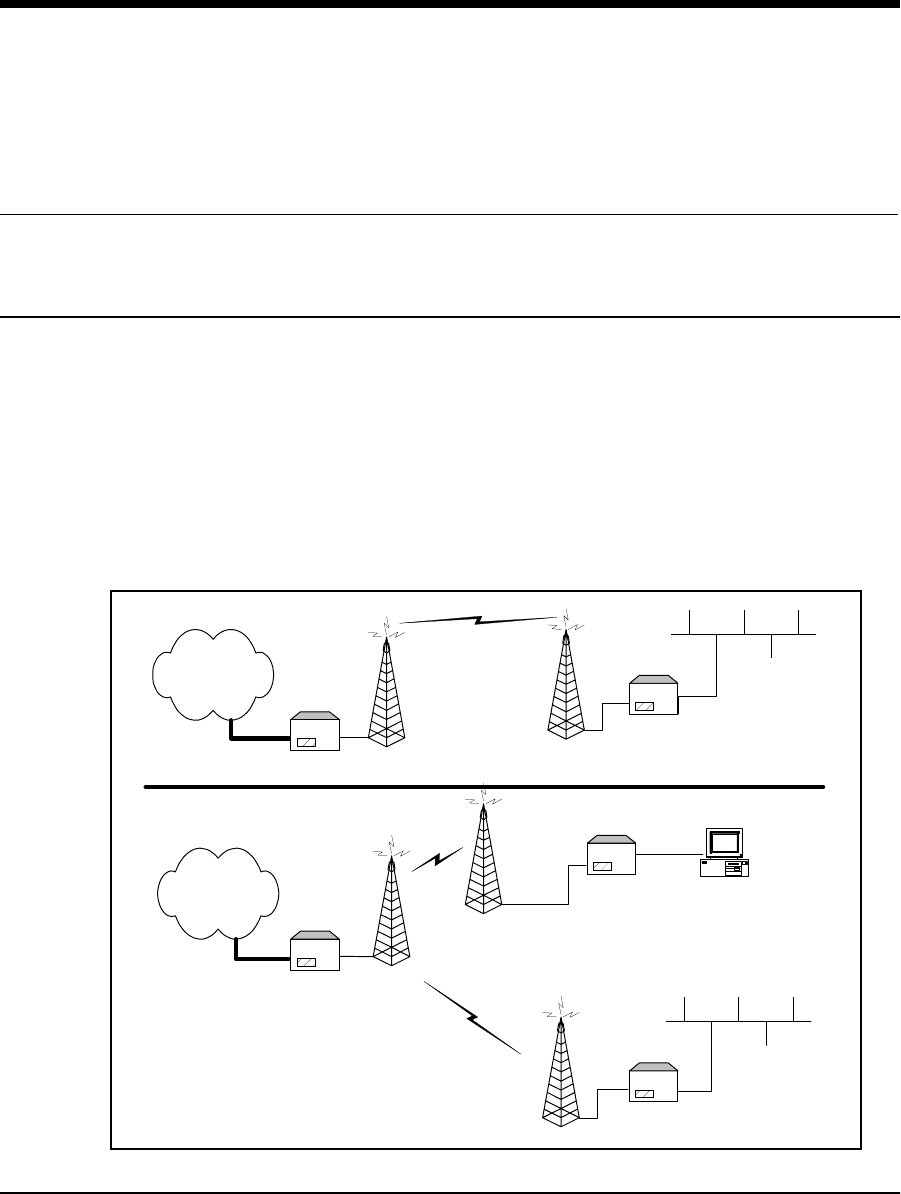
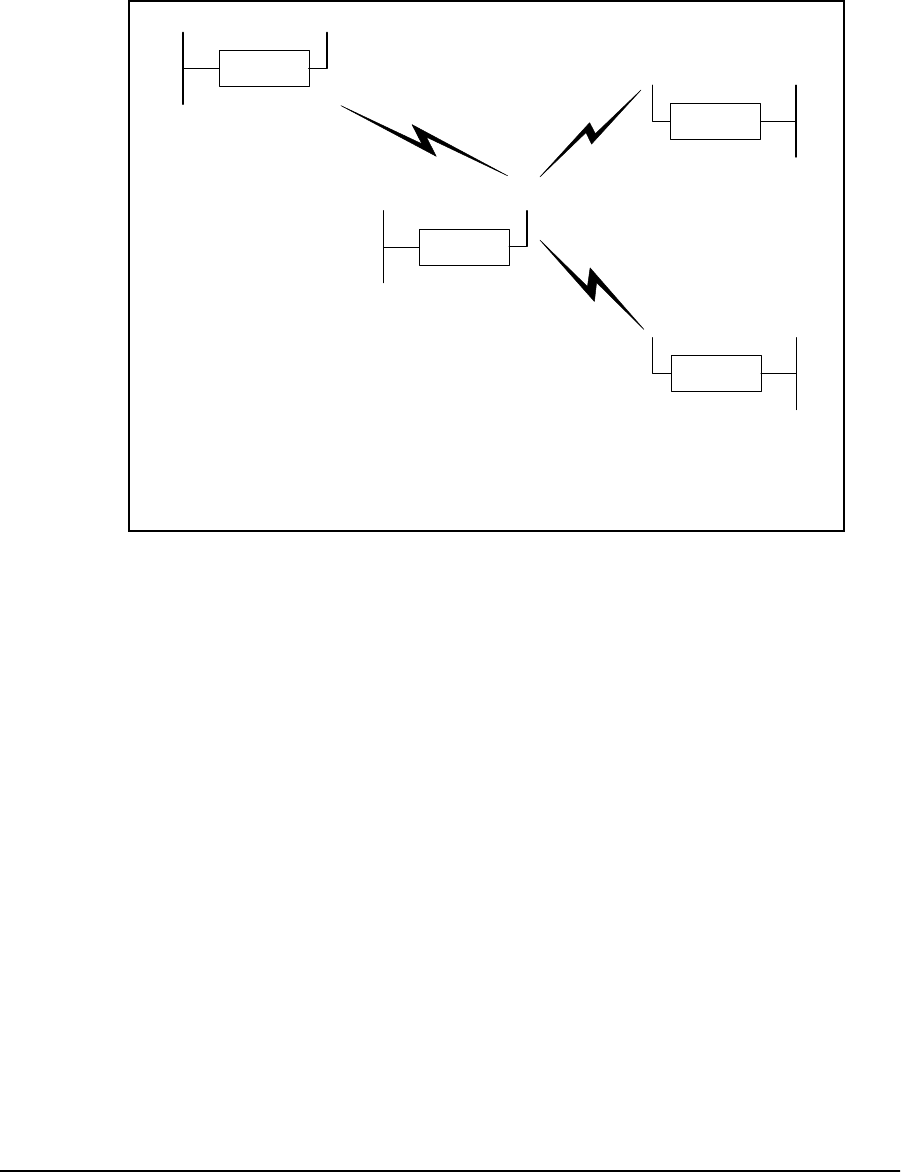
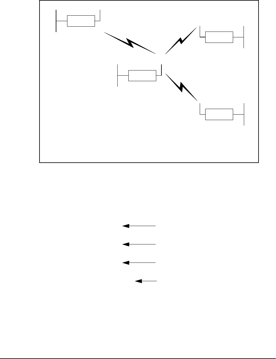
Figure 1 shows an NCL1135 point-to-point network and point-to-multipoint network.
Figure 1 NCL1135 Network Examples
Network
NCL1135
(Station)
Point-to-Point Network:
One Master and one
Station
Ethernet
NCL1135
(Master)
Network
NCL1135
(Station)
Point-to-Multipoint Network:
Up to 20 Stations per Master
NCL1135
(Station)
Ethernet
NCL1135
(Master)

1 NCL1135 Overview
2APCD–NC003–2.0A
The NCL1135 is used to extend Ethernet networks, access the Internet at high speed, connect
remote locations, and perform general data networking without the ongoing costs of leased
telephone or data lines.
1.2 Features
•Flexible deployment—WaveRider’s NCL1135 can operate as either a bridge or
router. In routing mode, the NCL1135 can be set up to use dynamic communications
strategies such as the Routing Information Protocol (RIP), Dynamic Host Control
Protocol (DHCP), and Open Shortest Path First (OSPF).
•Ethernet compatibility—WaveRider’s NCL1135 allows users to connect with most
Ethernet networks or devices.
•Microprocessor-controlled signal processing—All functions of WaveRider’s
spread-spectrum transceiver are controlled through the integration of a powerful
microprocessor.
•Architectural flexibility—WaveRider’s NCL1135 can be set up as a separate point-
to-point links, or in a mulitipoint configuration in which a single NCL1135 operating in
“master” mode can deliver data to and receive data from a maximum of 20 NCL1135
devices operating in “station” mode.
•User-configurable and -customizable monitoring—WaveRider’s NCL1135
operating system supports Simple Network Management Protocol (SNMP), which
allows for continual status monitoring of any NCL1135 in your network, and remote
upgrading.
•Low interference—WaveRider’s implementation of Direct Sequence Spread-
Spectrum (DSSS) technology transmits signal information over a wide channel
bandwidth, which reduces the potential for interference with neighboring
communications systems. WaveRider’s NCL1135 design permits three master units to
operate in close proximity without interfering with each other. For example, three
master units supporting 20 station units apiece can operate in close proximity, thus
providing 60 end-user links.
•Software-enabled feature sets—WaveRider offers NCL1135 users an easy,
customizable upgrade path through software-enabled feature optioning.

1 NCL1135 Overview
APCD–NC003–2.0A 3
1.3 About Spread-Spectrum Radio Technology
Spread-spectrum communications systems differ from conventional narrowband
communications systems because they use a much larger transmission bandwidth to send the
same amount of information.
There are two primary forms of spread spectrum—direct sequence and frequency hopping.
The NCL1135 uses direct-sequence spread-spectrum (DSSS). In DSSS systems, the
transmitted information, along with a digital spreading sequence, are used to modulate the
transmit carrier. The received signal is de-spread using the same digital spreading sequence,
and the information recovered.
Although spread spectrum appears complex and uses a wider bandwidth, DSSS offers the
following advantages for its use:
•Reduced power spectral density—Spreading over a wider bandwidth reduces the
spectral density (power per Hz of bandwidth) of the transmitted signal, allowing
simultaneous operation of many spread spectrum systems in the same frequency
band and geographic area. The reduced spectral density also allows you meet the
regulatory emissions requirements in frequency bands such as the ISM band.
•Transmission security—It is technologically more difficult to surreptitiously recover
(or jam, in the case of military communications systems) spread-spectrum signals
than it is to recover conventional narrowband signals.
•Interference suppression—The same mechanism that de-spreads the desired
signal in the receiver, also spreads undesired signals, which then appears to the
receiver as lower levels of RF noise.
For more information about spread spectrum communications, contact the WaveRider
Customer Support Centre.
— This page is intentionally left blank —

APCD–NC003–2.0A 5
2 Network Considerations
This section provides an overview of the network considerations that you should make before
beginning to implement an NCL1135 network. These network considerations include the
following:
•configuration
•mode: bridging or routing
•planning
2.1 Network Configuration
The NCL1135 can be deployed in three different network configurations:
•point-to-point
•repeater
•point-to-multipoint
Before deploying the system, you must determine the required network topology.
2 Network Considerations
6APCD–NC003–2.0A
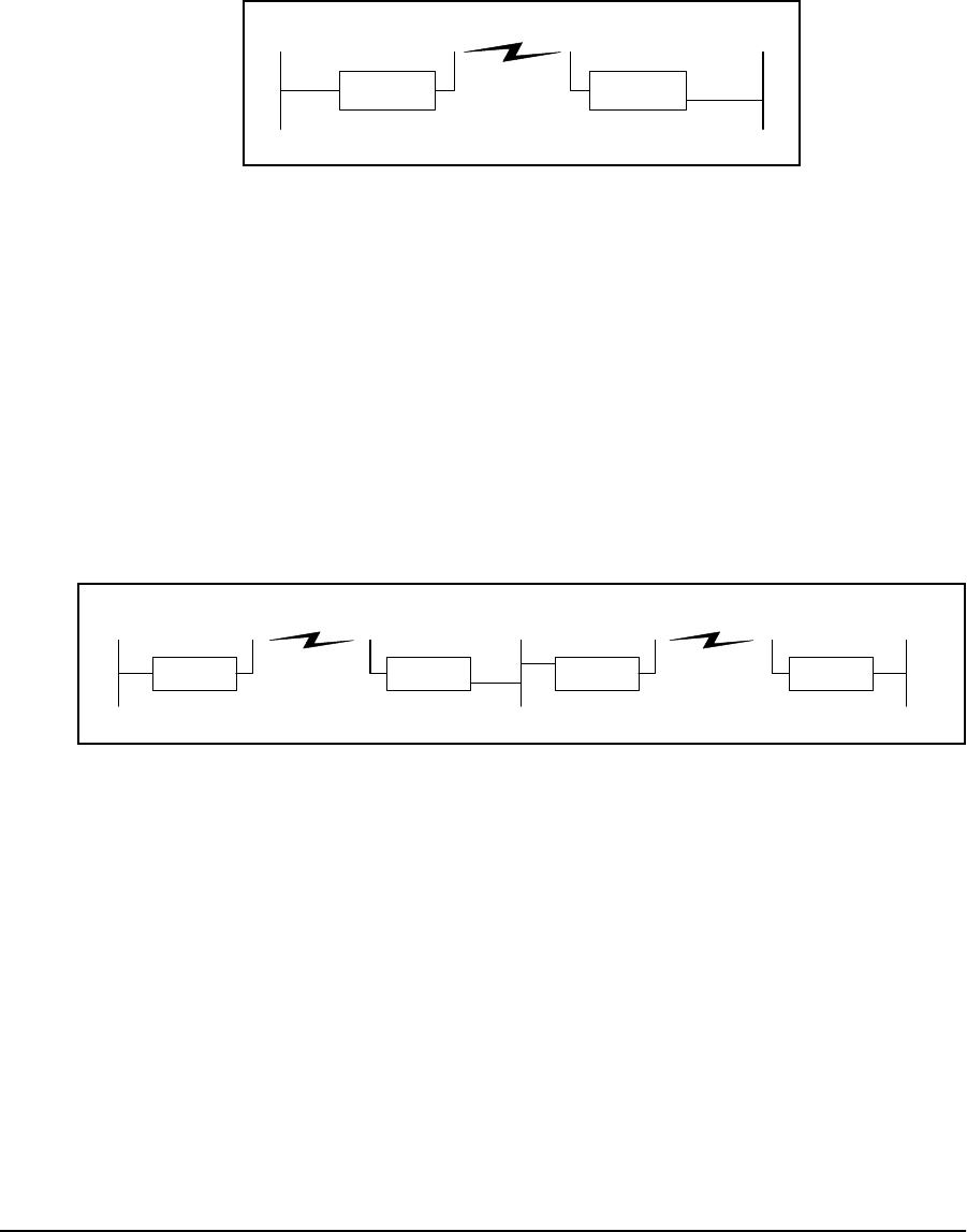
2.1.1 Point-to-Point
In a typical point-to-point application, shown in Figure 2, unit A communicates directly with unit
B. You can implement the link in either bridging or routing mode.
Figure 2 Point-to-Point Application
2.1.2 Repeater
You can set up a repeater by using two NCL1135 units back-to-back.
In the configuration shown in Figure 3, unit A communicates with unit B via the back-to-back
NCL1135 repeater configuration of units C and D. You must use different frequencies for each
leg of the path. Use this configuration to circumvent large obstacles in the radio link path, or
when the link from unit A to unit B is too long to provide reasonable signal levels and data
throughput.
Figure 3 Repeater Application
In this configuration, the effective data throughput from unit A to unit B is the same as the
lessor data throughput from unit A to unit C or unit D to unit B. That is, the throughput through
a series of links will be that of the slowest link.
You can implement this configuration in either bridging or routing mode.
NCL1135 NCL1135
AB
Ethernet EthernetRadio
B
NCL1135
Ethernet Radio Ethernet EthernetRadio
ACD
NCL1135 NCL1135 NCL1135
2 Network Considerations
APCD–NC003–2.0A 7
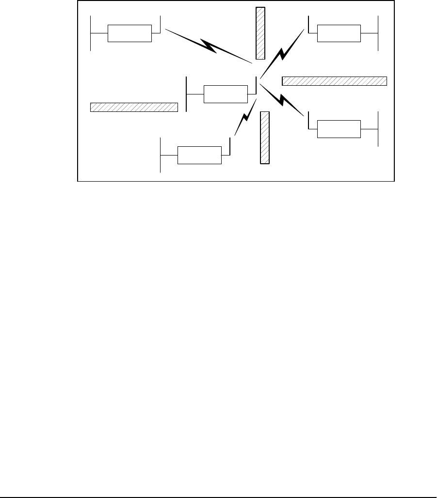
2.1.3 Point-to-Multipoint
Figure 4 shows an example point-to-multipoint configuration. The master, unit A, sends and
receives messages to and from NCL1135 stations. In this configuration, the throughput of unit
A is shared among the stations.
Although stations may receive communications from other stations, because of RF
propagation conditions, the stations are programmed to accept messages only from their
designated master.
Figure 4 Point-to-Multipoint Application
Radio
Ethernet
C
NCL1135
Ethernet
B
NCL1135
D
Ethernet
NCL1135
E
NCL1135
Ethernet
Ethernet
A
NCL1135
2 Network Considerations
8APCD–NC003–2.0A
2.2 Bridging and Routing Network Configurations
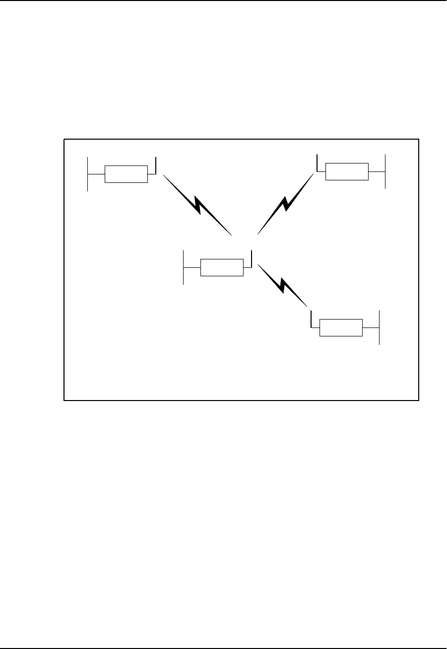
2.2.1 Point-to-Multipoint Bridging Network
In a point-to-multipoint network configuration, each NCL1135 must be configured as either a
bridge or router, not a mix of both operational modes. Figure 5 shows the configuration of a
typical point-to-multipoint bridging network.
Figure 5 Point-to-Multipoint Bridging Network Example
In Figure 5, unit A is configured as the network master and units B, C, and D as stations. Units
B, C, and D unit IDs must be manually added to the Remote Station List for unit A. The Master
ID on each station is set to the unit ID for Unit A. If a unit is not in the Master Remote Station
List and does not have the Master ID set to the unit ID for unit A, it will not be able to join the
network.
Ethernet
NCL1135
C
Ethernet
NCL1135
B
Ethernet
NCL1135
D
Ethernet Radio
NCL1135
A
Type: Station
Unit ID: 103
Radio Channel: 1
Mode: Bridging
IP Address - Ethernet: 10.0.2.103
Master ID: 1001
Type: Station
Unit ID: 102
Radio Channel: 1
Mode: Bridging
IP Address - Ethernet: 10.0.2.102
Master ID: 1001
Type: Station
Unit ID: 101
Radio Channel: 1
Mode: Bridging
IP Address - Ethernet: 10.0.2.101
Master ID: 1001
Type: Master
Unit ID: 1001
Radio Channel: 1
Mode: Bridging
IP Address - Ethernet: 10.0.2.44
Remote Station List: 101
102
103
2 Network Considerations
APCD–NC003–2.0A 9
2.2.2 Point-to-Multipoint Routing Network
Figure 6 shows the configuration of a typical point-to-multipoint routing network.
Figure 6 Point-to-Multipoint Routing Network Example
Ethernet
NCL1135
C
Ethernet
NCL1135
B
Ethernet
NCL1135
D
Ethernet Radio
NCL1135
A
Type: Station
Unit ID: 103
Radio Channel: 1
Mode: Routing
IP Address - Ethernet: 13.0.2.103
- Radio: 10.0.2.103
Master ID: 1001
Type: Station
Unit ID: 102
Radio Channel: 1
Mode: Routing
IP Address - Ethernet: 12.0.2.102
- Radio: 10.0.2.102
Master ID: 1001
Type: Station
Unit ID: 101
Radio Channel: 1
Mode: Routing
IP Address - Ethernet: 11.0.2.101
- Radio: 10.0.2.101
Master ID: 1001
Type: Master
Unit ID: 1001
Radio Channel: 1
Mode: Routing
IP Address - Ethernet: 14.0.2.44
- Radio: 10.0.2.44
Remote Station List: 101
102
103
2 Network Considerations
10 APCD–NC003–2.0A
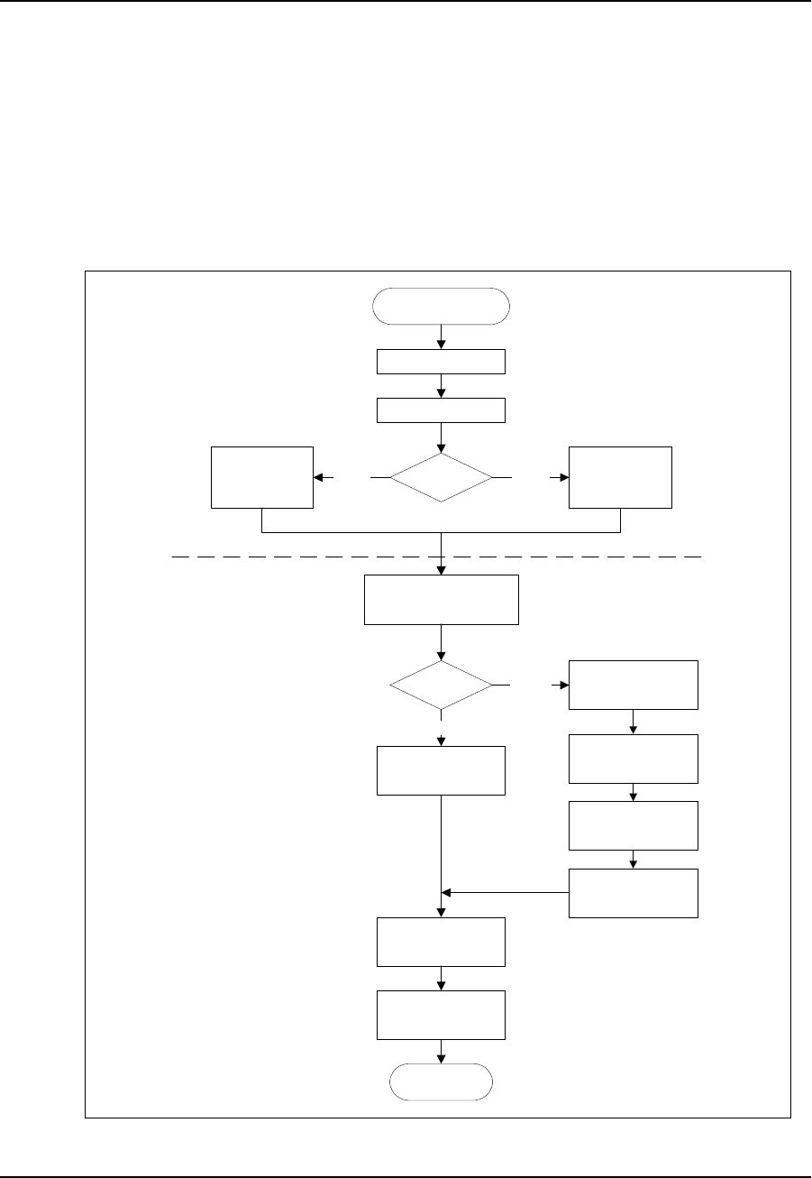
2.3 Planning an NCL1135 Configuration
Configuring each NCL1135 correctly is crucial to the proper operation of your network. Review
the flowchart in Figure 7 before starting the configuration to ensure that you have the
necessary information to configure the unit correctly.
Record your configuration options for each unit on a configuration record similar to the one
provided in Appendix E. Use the Configuration Data Record to help you plan your network and
keep track of NCL1135 network assignments.
Figure 7 NCL1135 Configuration Planning Flowchart
Start NCL1135
Configuration
Determine IP address and
subnet mask for Ethernet
interface
Bridging or
Routing?
Determine IP address
and subnet mask for
radio interface
(Optional)
Determine SNMP
configuration
Determine static routes
(Optional)
Determine DNS server
configuration
End NCL1135
Configuration
Routing
Bridge
IP Configuration
(Optional)
Determine DHCP Relay
configuration
(Optional)
Determine static routes
Master or
Station?
Determine radio
channel
Determine unit ID
Determine station
unit IDs for
Remote Station
List
Determine master
unit ID
StationMaster
Radio Configuration
(Optional)
Determine RIP
configuration

APCD–NC003–2.0A 11
3 Configuring the NCL1135
This section describes the steps required to initialize and configure the NCL1135 for use as
either a bridge or router, including the options available for routing and system monitoring.
NCL1135 users can perform these steps three ways:
•Telenet command line interface (CLI)
•Windows 95/98 graphical user interface (GUI)
•Internet Explorer/Netscape Communicator web browser
Before you begin these procedures, you should become familiar with the conventions used to
display the command-line syntax used in this manual. See NCL1135 Command-Line Syntax
Conventions on page 57. Table 7 on page 58 defines the keyboard shortcuts for entering
commands and requesting help.
NOTE: The following section describes the procedures for configuring
the NCL1135 via Telnet CLI. To download the Windows 95/98
GUI application, or more information on configuring the NCL1135
via web browser, visit WaveRider’s website at:
<http://www.waverider.com/techsupport/index.html>.
3 Configuring the NCL1135
12 APCD–NC003–2.0A
3.1 Connecting and Initializing the NCL1135
WARNING!
Antennas and associated transmission cable must be installed
by qualified personnel. Failure to terminate the antenna port
correctly can permanently damage the NCL1135. WaveRider
assumes no liability for failure to adhere to this recommendation
or to recognized general safety precautions.
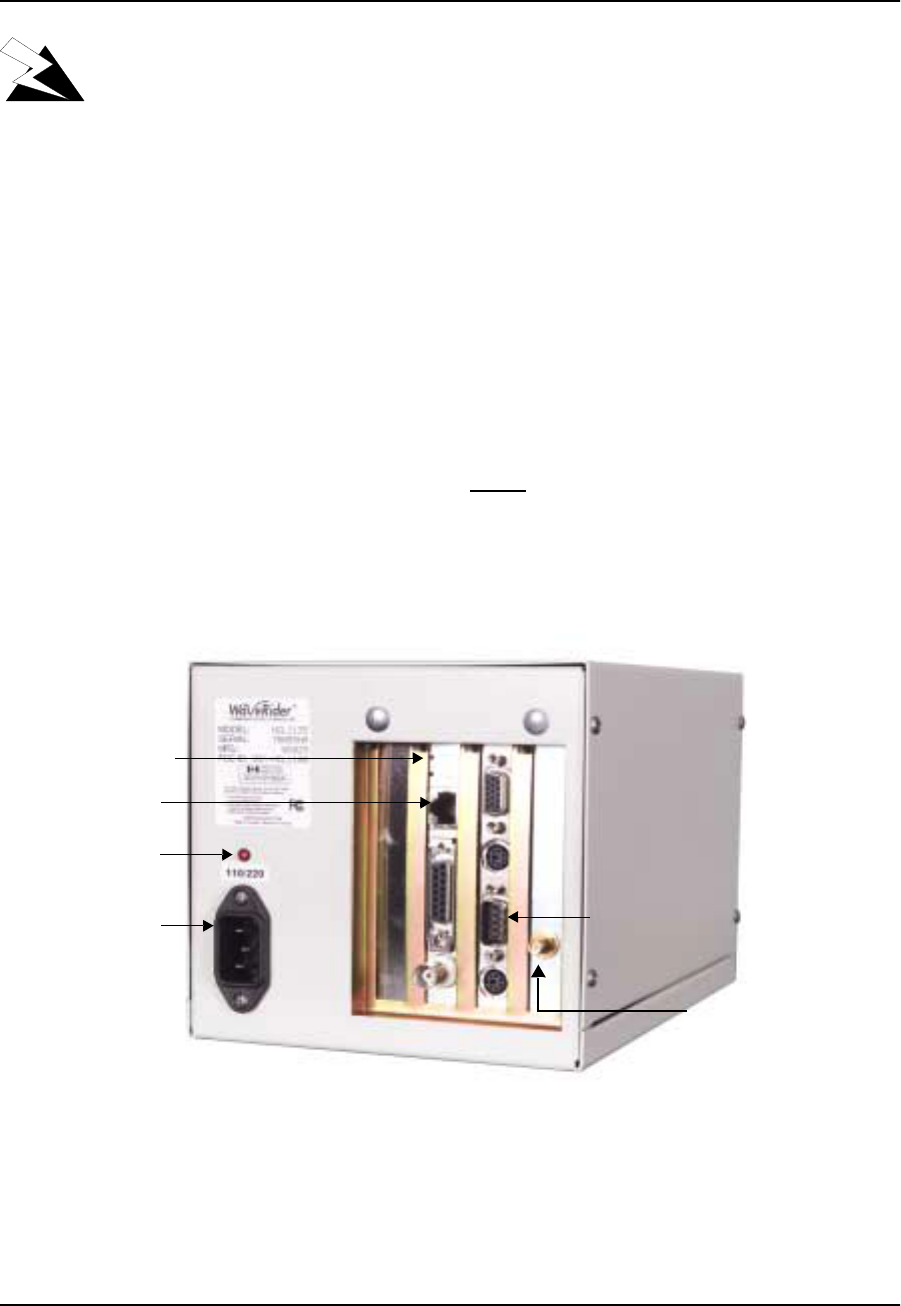
1. Attach the antenna or a 50-ohm load to the antenna connection on the back of the
NCL1135. Do NOT plug the NCL1135 to the power outlet until you have the antenna
or load connected.
NOTE: The NCL1135 is factory preset with the radio transmission
capabilities disabled to prevent equipment damage. However, as
a general precaution, WaveRider recommends that you always
connect the antenna or load before connecting to a power
source.
Figure 8 NCL1135 Connections
2. Use an RS-232 crossover cable to connect a terminal to the DB9 port.
NOTE: You can use any ASCII terminal to access the NCL1135, such as
a single-function terminal or a computer running terminal-
Ethernet Link LED
10BaseTx Ethernet
Connector (RJ-45)
Antenna Connector
(Reverse-Polarity SMA)
RS-232 Connector
(DB9 console port
RS-232 Connector
(DB9 console port
Power LED
Power Supply

3 Configuring the NCL1135
APCD–NC003–2.0A 13
emulation software. Figure 9 illustrates the pin-out for the console
port.
Figure 9 Console Port Pin-out Diagram
3. If you are using a terminal-emulation package, such as HyperTerminal, start the
application.
4. In the terminal-emulation application, select the communications port that you are
using to connect to the NCL1135.
5. Configure the application using the following settings:
•9600 bps
•8 data bits
•no parity
•1 stop bit
•no flow control
6. Plug the NCL1135 into a 110 or 220 V AC power source using the power cord
provided with the unit. The NCL1135 begins an initialization sequence displaying
progress messages on the terminal screen.
When it completes initialization, it displays a message to indicate that the system is
operational and the PASSWORD: prompt appears.
7. At the PASSWORD: prompt, press ENTER. The NCL1135 comes factory-configured
with no password.
8. Change the password for the NCL1135 by following the instructions in Changing the
NCL1135 Password, on page 14.
9. Change the system name in the NCL1135 as described in Setting the NCL1135
System Name, on page 15.
10. If the NCL1135 had been configured for use elsewhere in your network, reset the unit
by following the instructions is Resetting an NCL1135 to Factory Settings, on page 15.
If the NCL1135 is a factory-configured unit, you can omit this step.
The NCL1135 is now ready to be configured for your network.
DB9 Male DTE Configuration
Pin 2 Rx line
Pin 3 Tx line
Pin 5 Ground
9867
5
43
2
1

3 Configuring the NCL1135
14 APCD–NC003–2.0A
3.1.1 Changing the NCL1135 Password
You must be successfully connected and logged into the NCL1135.
For security, we recommend that you set the password for each unit in your network to a
unique password and that you record the password on the Configuration Data Record for the
group. Refer to Appendix E for a copy of the NCL1135 Network Group Configuration Data
Record.
1. At the NCL1135> prompt, type <system password>.
2. At the Enter Current Password: prompt, type the old password.
3. At the Enter New Password: prompt, type the new password.
TIP: Use a maximum of sixteen (16) alphanumeric,
ASCII characters. Passwords are case-sensitive. For
example, “abc” is not the same as “aBc”.
4. At the Verify password: prompt, type the new password again.
The system will display a message that your password has been successfully
changed.
5. Type <write> or <save> to save the settings to memory.
Your session to change the password may be similar to the following example session:
NCL1135> system password
Enter Current Password: *******
Enter New Password: ****
Verify password: ****
System password has been changed.
NCL1135>
CAUTION: Remember to record the password in your Data Configuration Record.
Unlocking the NCL1135 can be a complicated process. If you have forgotten the
password, contact the WaveRider Customer Support Centre for assistance.

3 Configuring the NCL1135
APCD–NC003–2.0A 15
3.1.2 Setting the NCL1135 System Name
You must be successfully connected and logged into the NCL1135.
1. At the NCL1135> prompt, type <system name your_system_name> to name the
NCL1135 in your system.
TIP: We recommend that you use a system name that
uniquely identifies the unit. You can use a name based on
its location, its purpose, or a combination of both. For
example, a system name, Station_firehall identifies the
NCL1135 configured as a Station and located at the
firehall.
The session to change the system name from NCL1135 to Station_firehall
would look like this:
NCL1135> system name Station_firehall
System name changed to: Station_firehall
Station_firehall>
2. Type <write> or <save> to save the settings to memory.
NOTE: In this User Manual, the command-line prompt will always be
shown as NCL1135>.
3.1.3 Resetting an NCL1135 to Factory Settings
If the NCL1135 is a factory-configured unit, the following procedure does not need to be
performed. Use this procedure if the NCL1135 had been previously configured for use
elsewhere in your network and you would like to prepare it for another location and use.
1. Connect the NCL1135 to a terminal or terminal-emulation software and at the
NCL1135> prompt, type <write erase> to reset the unit to its factory-default
settings.
2. Type <reboot> for the unit to recognize the factory-default settings.

3 Configuring the NCL1135
16 APCD–NC003–2.0A
3.2 Configuring the NCL1135
The procedures to configure the NCL1135 using a command-line interface are divided into two
main sections:
•Radio configuration — see Setting the Radio Configuration on page 16
•IP configuration — see Setting the IP Configuration on page 18
You can also configure the NCL1135 with the following options:
•Routing Information Protocol (RIP)—see Setting RIP Configuration on page 19
•Open Shortest Path First (OSPF)—see Setting OSPF Configuration on page 20
•Dynamic Host Control Protocol (DHCP) Relay—see Setting the DHCP Relay
Configuration on page 21
•Simple Network Management Protocol (SNMP)—see Setting the SNMP Configuration
on page 22
•Domain Name Server (DNS) Resolver—see Setting the DNS Resolver Configuration
on page 23
3.2.1 Setting the Radio Configuration
Before setting the radio configuration parameters, ensure that the NCL1135 has been
connected to a terminal and initialized as described in Connecting and Initializing the
NCL1135, on page 12 and you have changed the password as described in Changing the
NCL1135 Password, on page 14.
WARNING!
Antennas and associated transmission cable must be installed
by qualified personnel. Failure to terminate the antenna port
correctly can permanently damage the NCL1135. WaveRider
assumes no liability for failure to adhere to this recommendation
or to recognized general safety precautions.
1. Determine the radio channel for the network. See Appendix C for a list of operating
frequencies.
2. At the NCL1135> prompt, type <radio channel channel> to set the radio
channel for the NCL1135 where channel is the number of the network radio channel
on which it will be operating.
3. Determine the unit IDs for the Master and Stations for this NCL1135 network group.
The unit ID is a unique number, from 1 to 16383, that is used to identify the NCL1135
within the network group.
4. At the NCL1135> prompt, type <radio unitid unit_id> to set the NCL1135 unit
ID.

3 Configuring the NCL1135
APCD–NC003–2.0A 17
5. Set the NCL1135 as a Master or Station. To set the NCL1135 as a Master, type
<radio type master>. To set the NCL1135 as a Station, type <radio type
station>.
6. If the NCL1135 is a Master, add the unit IDs for the Stations that are configured for this
network group. At the NCL1135> prompt, type <radio station add
station_unitid> where station_unitid is the unit ID for a Station.
NOTE: To remove a Station from the Remote Station List, type <radio
station del station_unitid> where station_unitid
is the unit ID for the Station you want removed.
7. Repeat step 6 for each Station that you want to add to the Remote Station List for the
Master NCL1135. A maximum of 20 Stations can be added to one Master.
8. If the NCL1135 is a Station, add the Master unit ID for the network group. At the
NCL1135> prompt, type <radio masterID master_unitid> where
master_unitid is the unit ID for Master NCL1135 in the network group.
9. At the NCL1135> prompt, type <write> to save the settings to memory.
TIP: To display a list of Stations associated with a Master
NCL1135, type <radio station> at the NCL1135>
prompt.

3 Configuring the NCL1135
18 APCD–NC003–2.0A
3.2.2 Setting the IP Configuration
Ensure that the NCL1135 has been connected to a terminal and initialized as described in
Connecting and Initializing the NCL1135, on page 12 and you have changed the password as
described in Changing the NCL1135 Password, on page 14.
Complete the radio configuration as described in Setting the IP Configuration, on page 18
before configuring the IP configuration options.
1. At the NCL1135> prompt, type <ip address ethernet aaa.bbb.ccc.ddd nn>
to set the IP address for the Ethernet interface. aaa.bbb.ccc.ddd is the IP address
of the NCL1135 and nn is the number of bits in the subnet mask (for example, 24
represents a subnet mask of 255.255.255.0).
2. At the NCL1135> prompt, type <mode bridging> or <mode routing> to set the
forwarding mode.
3. If the mode is set to bridging in Step 2, omit this step. If the mode is routing, type <ip
address radio remote_unit_id aaa.bbb.ccc.ddd eee.fff.ggg.hhh> to
set the IP address for the radio interface to the remote unit. aaa.bbb.ccc.ddd is
the IP address for the local unit and eee.fff.ggg.hhh is the IP address for the
remote unit.
NOTE: If you change the radio IP address for a Station at a later time,
remember to update the Master with the new Station IP address.
If you change the radio IP address for a Master at a later time,
remember to update each Station in the Remote Station List with
the new remote IP address for the Master.
4. For a Master unit, repeat step 3 for every Station in the group. For a Station unit, you
only need to enter the remote unit IP address for the Master.
5. You can optionally add a maximum of 256 static routes for the NCL1135. At the
NCL1135> prompt, type <ip route add aaa.bbb.ccc.ddd
eee.fff.ggg.hhh subnet_mask> where aaa.bbb.ccc.ddd is the IP address
for the destination network, eee.fff.ggg.hhh is the IP address for the gateway,
and subnet_mask is specified in the number of bits.
6. If the mode is routing and the NCL1135 is a Master, type <ip route add
station_ethernet_subnet station_radio_ip_address subnet_mask> to
route the Master subnet traffic to the Master.
7. If the mode is routing and the NCL1135 is a Station, type <ip route add 0.0.0.0
master_radio_ip_address 0> to add a default static route to route all unknown
subnets through the Master.
8. At the NCL1135> prompt, type <radio enable> to enable the NCL1135 to transmit
messages. Ensure that the NCL1135 antenna port is terminated.
9. At the NCL1135> prompt, type <write> to save the settings to memory.
10. When done configuring the NCL1135, disconnect the terminal from the NCL1135.

3 Configuring the NCL1135
APCD–NC003–2.0A 19
3.2.3 Configuration Options
The NCL1135 provides users with the following configuration options:
in Routing Mode
•Routing Information Protocol (RIP)—see Setting RIP Configuration on page 19
•Open Shortest Path First (OSPF)—see Setting OSPF Configuration on page 20
•Dynamic Host Control Protocol (DHCP) Relay—see Setting the DHCP Relay
Configuration on page 21
for System Monitoring
•Simple Network Management Protocol (SNMP)—see Setting the SNMP Configuration
on page 22
•Domain Name Server (DNS) Resolver—see Setting the DNS Resolver Configuration
on page 23
After completing these procedures, it is important to confirm that the configuration is correct
before deploying the NCL1135 in the field. Refer to Chapter 4, Testing, on page 35.
Two example configuration diagrams and sessions are provided in Examples of Bridging and
Routing Configurations, on page 24: one for a point-to-multipoint bridging, and the second for
a point-to multipoint routing network.
Setting RIP Configuration
When the NCL1135 is in Routing Mode, you can optionally enable the Routing Information
Protocol (RIP) features. RIP is a protocol that runs between two routers (for example, two
NCL1135s) or a route server in order toexchange information about routes. When RIP is
active, RIP can be configured to “advertise” default routes or static routes.
The NCL1135 supports both RIP version 1 and 2. RIP version 2 can be set as broadcast,
compatible, or multicast.
1. At the NCL1135> prompt, type <ip routing rip> to enable RIP as the routing
mode.
2. To transmit the route information in packets, type <ip rip active>. If RIP is set to
quiet, it receives and processes RIP packets, but it does not transmit them.
3. Type <ip rip version> to display the current version of RIP.
4. If RIP is version 1, it is broadcast only. To change RIP routing to support version 2,
type <ip rip version 2>.
5. If you set RIP to version 2, you can additionally specify how RIP handles packets.
To do this.... Type...
Send version 2 advertisements as broadcast. <ip rip broadcast>

3 Configuring the NCL1135
20 APCD–NC003–2.0A
6. To enable RIP to advertise the default route, if one exists, in the advertisement, type
<ip rip default>.
To send RIP to advertise static routes, as well as all other RIP information, type
<ip rip update>. noupdate sends all route information except static route information.
Setting OSPF Configuration
The Open Shortest Path First (OSPF) routing protocol generates an IP network layer database
and forwards that information to all other routers within the same network to determine the
shortest path between nodes. OSPF is compatible with other routing protocols and does not
affect packet content.
OSPF routing decisions are based on a Link-State Algorithmn (or Advertisement), which
allows faster delivery of packetized data, particularily within larger corporate and institutional
intranetworks, because each router is aware of the set of links used by every other router,
rather than only those of its adjacent router. In an OSPF-enabled environment, whenever a
router becomes aware of another router on one of its attached subnetworks, it creates a
logical link to that system, and treats it as a ‘neighbour’.
Send more compatible version 1 broadcasts (intended
for version 1 routers). <ip rip compatible>
Disable RIP routing. <ip rip disable>
Enable RIP routing. <ip rip enable>
Send version 2 advertisements to RIP version 2
multicast addresses. This is generally more efficient
than broadcast.
<ip rip multicast>
To do this.... Type...
To do this.... Type...
Display OSPF area configuration <ip ospf area>
Add an OSPF area <ip ospf area add>
<Area aaa.bbb.ccc.ddd>
Delete an OSPF area <ip ospf area del>
<Area aaa.bbb.ccc.ddd>
Disable OSPF protocol. <ip ospf disable>
Enable OSPF protocol. <ip ospf enable>
Configure interface parameters. <ip ospf interface>
<interface>
<Area.aaa.bbb.ccc.ddd>
<Cost 0-65535>

3 Configuring the NCL1135
APCD–NC003–2.0A 21
Setting the DHCP Relay Configuration
When the NCL1135 is in Routing mode, you can optionally enable Dynamic Host Control
Protocol (DHCP) Relay which makes the NCL1135 aware of the protocol for DHCP traffic and
forward the responses back to the designated DHCP Server.
NOTE: DHCP Relay is transparent when the NCL1135 is in bridging
mode and, therefore, is not available in that mode.
You can configure a maximum of five DHCP servers in the NCL1135 configuration.
1. At the NCL1135> prompt, type <dhcp mode relay> to enable DHCP Relay in the
device.
2. To add a DHCP server, type <dhcp relay add ip_address> where
ip_address is the IP Address for the DHCP Server available for the NCL1135 to
forward and receive DHCP traffic.
3. At the NCL1135> prompt, type <write> to save the settings to memory.
NOTE: To remove a DHCP server, type <dhcp relay delete
ip_address>. To disable DHCP Relay, type <dhcp mode
none>.

3 Configuring the NCL1135
22 APCD–NC003–2.0A
Setting the SNMP Configuration
SNMP enables a network management station to monitor, control, and remotely configure
network devices called agents.
SNMP allows you to look at SNMP variables using READ communities, and to set SNMP
variables using WRITE communities. Communities are optional on the NCL1135, but it can
support a maximum of five communities. An NCL1135 comes factory-configured with two
communities, a READ community called public and a WRITE community called private.
SNMP also provides a mechanism called trap, which notifies a network management station
that a significant event took place. A significant event can be an interface going down or
coming up, a unit performing a cold or warm start, or an authentication failure. Refer to RFC
1157 for details.
Associated with SNMP are Management Information Bases (MIBs). These specify a collection
of management information available from the agent. This information can be controlled and
monitored from a network management station.
The NCL1135 implements SNMPv2c and includes a number of standard SNMP MIBs:
•RFC1157 (MIB-Il)
•RFC1493 (bridging)
•an NCL1135-specific MIB
WaveRider MIBs can be downloaded from the technical support page at www.waverider.com.
The following procedure describes how to configure standard SNMP communities for read/
write access to the NCL1135 SNMP agent and to specify a server IP address to which trap
messages are sent.
1. At the NCL1135> prompt, type <snmp> to display the current SNMP settings for the
NCL1135.
2. To add a new community, type <snmp community add community
READ|WRITE> where community is the name of the community and READ|WRITE
is the community type. You can have a maximum of five communities.
3. If a community is not set up the way you want it, delete it by typing
<snmp community del community READ|WRITE> where community is the
name of the community and READ|WRITE is the community type.
4. At the NCL1135> prompt, type <snmp location location> to change the
geographical location of the NCL1135.
5. Type <snmp contact contact> to change the contact name for the NCL1135. The
contact can be a name and phone number, a URL, or an email address.
6. To add a trap server to the NCL1135 configuration, type <snmp trap add
aaa.bbb.ccc.ddd community> where aaa.bbb.ccc.ddd is the IP address of
the trap server and community is the name of the community on the trap server.
7. To delete a trap server from the NCL1135 configuration, type <snmp trap del
aaa.bbb.ccc.ddd community> where aaa.bbb.ccc.ddd is the IP address of
the trap server and community is the name of the community on the trap server.
8. At the NCL1135> prompt, type <write> to save the settings to memory.

3 Configuring the NCL1135
APCD–NC003–2.0A 23
Setting the DNS Resolver Configuration
The NCL1135 implements DNS resolver software. Once you configure the NCL1135, you can
use host names instead of IP addresses when you make a Telnet connection from the
NCL1135 console to other IP hosts on the network, or when you send ping messages to test
connectivity.
Adding DNS server lists is optional on the NCL1135, but you can configure the NCL1135 to
use a maximum of five DNS servers. An NCL1135 comes factory-configured with no DNS
servers in the list.
You can also configure the NCL1135 with a domain name for your local IP network.
The following procedure describes how to configure the NCL1135 to implement DNS resolver
software and configure the NCL1135 domain name. Setting the DNS resolver configuration is
optional.
1. At the NCL1135> prompt, type <ip dns> to display the current DNS setup used by
the NCL1135.
2. To add a DNS Server, type <ip dns server add aaa.bbb.ccc.ddd> where
aaa.bbb.ccc.ddd is the IP address of the DNS Server.
3. To delete a DNS Server, type <ip dns server del aaa.bbb.ccc.ddd> where
aaa.bbb.ccc.ddd is the IP address of the DNS Server.
4. To set the domain name for your local IP network, type <ip dns domain
domain_name> where domain_name is the name for your local IP network.
5. At the NCL1135> prompt, type <write> to save the settings to memory.
3 Configuring the NCL1135
24 APCD–NC003–2.0A
3.3 Examples of Bridging and Routing Configurations
The following two examples for a point-to-multipoint network configuration provide detailed
diagrams for a bridging and routing configuration and the corresponding command-line
sessions to configure the appropriate devices in the network.
In a point-to-multipoint network configuration, all the NCL1135s in the network must be either
configured as bridges or routers, not a mix of both operational modes.
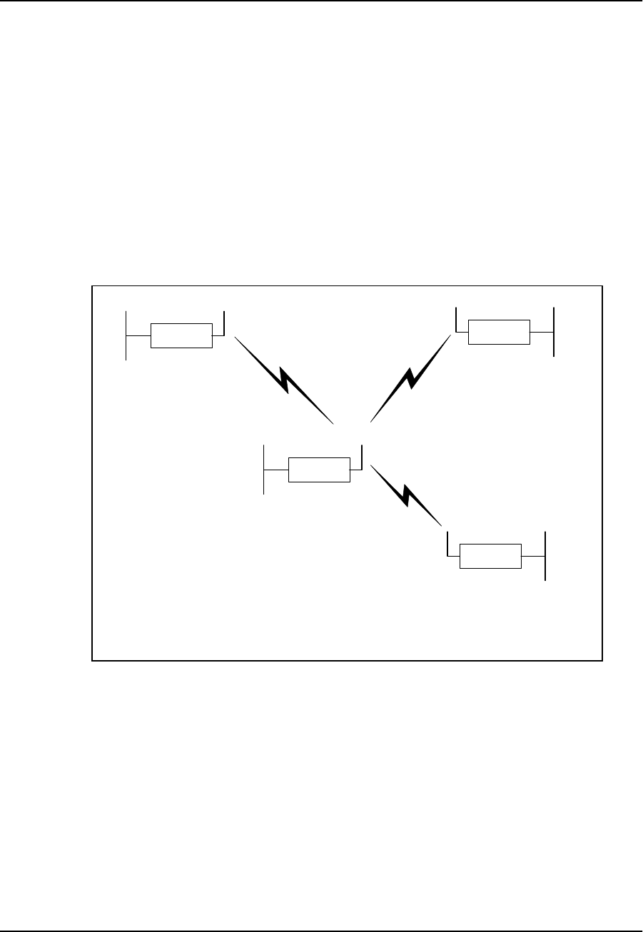
3.3.1 Point-to-Multipoint Bridging Network
Figure 10 shows a configuration of a typical point-to-multipoint bridging network.
Figure 10 Example Point-to-Multipoint Bridging Network
In Figure 10, unit A has been configured as the Master of the system with remote units B, C,
and D configured as Stations. Units B, C, and D unit IDs have been manually added to the
Master (unit A) Remote Station List. The Master unit ID on each Station is set to the unit ID for
unit A. If a unit is not in the Master Remote Station List and does not have the Master unit ID
set, it will not be able to join the network.
The following example session shows how to configure the Master NCL1135 for the bridging
network shown in Figure 10.
Ethernet
NCL1135
C
Ethernet
NCL1135
B
Ethernet
NCL1135
D
Ethernet Radio
NCL1135
A
Type: Station
Unit ID: 103
Radio Channel: 1
Mode: Bridging
IP Address - Ethernet: 10.0.2.103
Master ID: 1001
Type: Station
Unit ID: 102
Radio Channel: 1
Mode: Bridging
IP Address - Ethernet: 10.0.2.102
Master ID: 1001
Type: Station
Unit ID: 101
Radio Channel: 1
Mode: Bridging
IP Address - Ethernet: 10.0.2.101
Master ID: 1001
Type: Master
Unit ID: 1001
Radio Channel: 1
Mode: Bridging
IP Address - Ethernet: 10.0.2.44
Remote Station List: 101
102
103

3 Configuring the NCL1135
APCD–NC003–2.0A 25
NCL1135>
NCL1135> radio channel 1
Radio channel changed to: 1
NCL1135> radio unitid 1001
Unit ID changed to: 1001
NCL1135> radio type master
Radio type changed to: Master
NCL1135> radio station add 101
Station added.
NCL1135> radio station add 102
Station added.
NCL1135> radio station add 103
Station added.
NCL1135> radio
RADIO CONFIGURATION:
Radio type : Master
Wireless ID : 1001
Speed : 11Mbs
Channel : 1
Regulatory Domain : FCC/IC
Frequency : 2.412 GHz
Interframe spacing: 32 (281.6 micro seconds)
Hardware address : 00:90:27:CA:62:A3
Network Card IRQ : 5
NIC Base Address : 0x0d0000
Remote Stations : 101
: 102
: 103
NCL1135> ip address ethernet 10.0.2.44 16
IP addresses:
Ethernet: 10.0.2.44/16
NCL1135> mode bridging
Forwarding mode: Bridging
NCL1135> ip
Forwarding Mode: BRIDGING
Addresses:
Ethernet: 10.0.2.44/16
Routing: IP Routing (Static Only)
Routing Table:
Destination Mask Gateway Flags Protocol Interface
--------------------------------------------------------------------
10.0.0.0 16 10.0.2.44 UC Local eeE0
10.0.2.44 0 10.0.2.44 UHL ICMP lo0
127.0.0.1 0 127.0.0.1 UH Local lo0
--------------------------------------------------------------------
DNS Domain Name:
DNS Servers:
No DNS servers defined.
NCL1135> write
Sets the radio channel
Sets the NCL1135 unit ID
Sets the NCL1135 type to Master
Adds a station to the Master Remote
Station List
Displays the radio configuration
information
Changes the local
Ethernet IP address
Sets the mode to bridging
Displays the IP configuration
information
Saves the configuration

3 Configuring the NCL1135
26 APCD–NC003–2.0A
The following example session shows how to configure Station B in Figure 10 to join the
network. To configure the remaining Stations, use the same procedure, replacing the unit ID
and IP address for each with the appropriate information for that Station.
NCL1135>
NCL1135> radio channel 1
Radio channel changed to: 1
NCL1135> radio unitid 101
Unit ID changed to: 101
NCL1135> radio type station
Radio type changed to: Station
NCL1135> radio masterid 1001
Master Id changed to: 1001
NCL1135> ip address ethernet 10.0.2.101 16
IP addresses:
Ethernet: 10.0.2.101/16
NCL1135> mode bridging
Forwarding mode: Bridging
NCL1135> radio
RADIO CONFIGURATION:
Radio type : Station
Wireless ID : 101
Speed : 11Mbs
Channel : 1
Regulatory Domain : FCC/IC
Frequency : 2.412 GHz
Interframe spacing: 32 (281.6 micro seconds)
Hardware address : 00:90:27:CA:62:A3
Network Card IRQ : 5
NIC Base Address : 0x0d0000
Master ID : 1001
NCL1135> ip
Forwarding Mode: BRIDGING
Addresses:
Ethernet: 10.0.2.101/16
Routing: IP Routing (Static Only)
Routing Table:
Destination Mask Gateway Flags Protocol Interface
--------------------------------------------------------------------
10.0.0.0 16 10.0.2.101 UC Local eeE0
10.0.2.101 0 10.0.2.101 UHL ICMP lo0
127.0.0.1 0 127.0.0.1 UH Local lo0
--------------------------------------------------------------------
DNS Domain Name:
DNS Servers:
No DNS servers defined.
NCL1135> write
Sets the NCL1135 type to Station
Identifies the unit ID of the Master for
this Station
3 Configuring the NCL1135
APCD–NC003–2.0A 27
3.3.2 Point-to-Multipoint Routing Network
Figure 11 shows a configuration of a typical point-to-multipoint routing network.
Figure 11 Example Point-to-Multipoint Routing Network
The following example session shows how to configure the Master NCL1135 for the routing
network shown in Figure 11.
NCL1135>
NCL1135> ip address ethernet 14.0.2.44 16
IP addresses:
Ethernet: 14.0.2.44/16
NCL1135> mode routing
Forwarding mode: IP Routing
ncl1135> dhcp
DHCP Disabled
ncl1135> dhcp mode relay
DHCP Relay Enabled
ncl1135> dhcp relay add 10.0.1.44
DHCP Servers/Relay Agents:
10.0.1.44
NCL1135> radio channel 1
NCL1135> radio type master
Radio type changed to: Master
NCL1135> radio unitid 1001
Unit ID changed to: 1001
Ethernet
NCL1135
C
Ethernet
NCL1135
B
Ethernet
NCL1135
D
Ethernet Radio
NCL1135
A
Type: Station
Unit ID: 103
Radio Channel: 1
Mode: Routing
IP Address - Ethernet: 13.0.2.103
- Radio: 10.0.2.103
Master ID: 1001
Type: Station
Unit ID: 102
Radio Channel: 1
Mode: Routing
IP Address - Ethernet: 12.0.2.102
- Radio: 10.0.2.102
Master ID: 1001
Type: Station
Unit ID: 101
Radio Channel: 1
Mode: Routing
IP Address - Ethernet: 11.0.2.101
- Radio: 10.0.2.101
Master ID: 1001
Type: Master
Unit ID: 1001
Radio Channel: 1
Mode: Routing
IP Address - Ethernet: 14.0.2.44
- Radio: 10.0.2.44
Remote Station List: 101
102
103
Sets the mode to routing
DHCP Relay is disabled by default
Enable DHCP Relay
Add a DHCP Server to the DHCP
Relay table

3 Configuring the NCL1135
28 APCD–NC003–2.0A
NCL1135> radio station add 101
Station added.
NCL1135> radio station add 102
Station added.
NCL1135> radio station add 103
Station added.
NCL1135> ip
Forwarding Mode: IP ROUTING
Addresses:
Ethernet: 14.0.2.44/16
Radio: 101, 10.0.2.44 p-t-p ?
102, 10.0.2.44 p-t-p ?
103, 10.0.2.44 p-t-p ?
Routing: IP Routing (Static Only)
Routing Table:
Destination Mask Gateway Flags Protocol Interface
--------------------------------------------------------------------
14.0.2.44 0 14.0.2.44 UHL ICMP lo0
14.0.0.0 16 14.0.2.44 UC Local eeE0
127.0.0.1 0 127.0.0.1 UH Local lo0
--------------------------------------------------------------------
DNS Domain Name:
DNS Servers:
No DNS servers defined.
NCL1135> radio
RADIO CONFIGURATION:
Radio type : Master
Wireless ID : 1001
Speed : 11Mbs
Channel : 1
Regulatory Domain : FCC/IC
Frequency : 2.412 GHz
Interframe spacing: 32 (281.6 micro seconds)
Hardware address : 00:90:27:CA:62:A3
Network Card IRQ : 5
NIC Base Address : 0x0d0000
Remote Stations : 101
: 102
: 103
NCL1135> ip address radio 101 10.0.2.44 10.0.2.101
IP addresses:
Ethernet: 14.0.2.44/16
Radio: 101, 10.0.2.44 p-t-p 10.0.2.101
102, 10.0.2.44 p-t-p ?
103, 10.0.2.44 p-t-p ?
NCL1135> ip address radio 102 10.0.2.44 10.0.2.102
IP addresses:
Ethernet: 14.0.2.44/16
Radio: 101, 10.0.2.44 p-t-p 10.0.2.101
102, 10.0.2.44 p-t-p 10.0.2.102
103, 10.0.2.44 p-t-p ?
NCL1135> ip address radio 103 10.0.2.44 10.0.2.103
IP addresses:
Ethernet: 14.0.2.44/16
Radio: 101, 10.0.2.44 p-t-p 10.0.2.101
102, 10.0.2.44 p-t-p 10.0.2.102
103, 10.0.2.44 p-t-p 10.0.2.103
Displays the IP configuration
information
The ? means that the IP address for
the remote unit in the routing network
has not been set
Sets the radio IP
address for the route to
station B (unit ID 101)
Sets the radio IP
address for the route to
station C (unit ID 102)
Sets the radio IP
address for the route to
station D (unit ID 103)

3 Configuring the NCL1135
APCD–NC003–2.0A 29
NCL1135> ip route add 11.0.0.0 10.0.2.101 16
Routing Table:
Destination Mask Gateway Flags Protocol Interface
--------------------------------------------------------------------
14.0.2.44 0 14.0.2.44 UHL ICMP lo0
10.0.2.101 0 10.0.2.44 UHC Local mdr1
10.0.2.102 0 10.0.2.44 UHC Local mdr2
10.0.2.103 0 10.0.2.44 UHC Local mdr3
14.0.0.0 16 14.0.2.44 UC Local eeE0
11.0.0.0 16 10.0.2.101 UC Static mdr1
127.0.0.1 0 127.0.0.1 UH Local lo0
--------------------------------------------------------------------
NCL1135> ip route add 12.0.0.0 10.0.2.102 16
Routing Table:
Destination Mask Gateway Flags Protocol Interface
--------------------------------------------------------------------
14.0.2.44 0 14.0.2.44 UHL ICMP lo0
10.0.2.101 0 10.0.2.44 UHC Local mdr1
10.0.2.102 0 10.0.2.44 UHC Local mdr2
10.0.2.103 0 10.0.2.44 UHC Local mdr3
14.0.0.0 16 14.0.2.44 UC Local eeE0
11.0.0.0 16 10.0.2.101 UC Static mdr1
12.0.0.0 16 10.0.2.102 UC Static mdr2
127.0.0.1 0 127.0.0.1 UH Local lo0
--------------------------------------------------------------------
NCL1135> ip route add 13.0.0.0 10.0.2.103 16
Routing Table:
Destination Mask Gateway Flags Protocol Interface
--------------------------------------------------------------------
14.0.2.44 0 14.0.2.44 UHL ICMP lo0
10.0.2.101 0 10.0.2.44 UHC Local mdr1
10.0.2.102 0 10.0.2.44 UHC Local mdr2
10.0.2.103 0 10.0.2.44 UHC Local mdr3
14.0.0.0 16 14.0.2.44 UC Local eeE0
11.0.0.0 16 10.0.2.101 UC Static mdr1
12.0.0.0 16 10.0.2.102 UC Static mdr2
13.0.0.0 16 10.0.2.103 UC Static mdr3
127.0.0.1 0 127.0.0.1 UH Local lo0
--------------------------------------------------------------------
NCL1135> ip
Forwarding Mode: IP ROUTING
Addresses:
Ethernet: 14.0.2.44/16
Radio: 101, 10.0.2.44 p-t-p 10.0.2.101
102, 10.0.2.44 p-t-p 10.0.2.102
103, 10.0.2.44 p-t-p 10.0.2.103
Routing: IP Routing (Static Only)
Routing Table:
Destination Mask Gateway Flags Protocol Interface
--------------------------------------------------------------------
14.0.2.44 0 14.0.2.44 UHL ICMP lo0
10.0.2.101 0 10.0.2.44 UHC Local mdr1
10.0.2.102 0 10.0.2.44 UHC Local mdr2
10.0.2.103 0 10.0.2.44 UHC Local mdr3
14.0.0.0 16 14.0.2.44 UC Local eeE0
11.0.0.0 16 10.0.2.101 UC Static mdr1
12.0.0.0 16 10.0.2.102 UC Static mdr2
13.0.0.0 16 10.0.2.103 UC Static mdr3
127.0.0.1 0 127.0.0.1 UH Local lo0
--------------------------------------------------------------------
DNS Domain Name:
For each Station,
route the Ethernet
subnet to the radio
IP address of the
Station
Note the IP addresses
for the remote Stations
are now set

3 Configuring the NCL1135
30 APCD–NC003–2.0A
DNS Servers:
No DNS servers defined.
NCL1135> write
The following example session shows how to configure Station B in Figure 11 to join the
routing network. To configure the remaining Stations, use the same procedure, replacing the
unit ID for each Station with the appropriate ID for that Station.
NCL1135>
NCL1135> ip address ethernet 11.0.2.101 16
IP addresses:
Ethernet: 11.0.2.101/16
Radio: 200, 10.0.2.44 p-t-p ?
ncl1135> dhcp mode relay
DHCP Relay Enabled
ncl1135> dhcp relay add 10.0.1.44
DHCP Servers/Relay Agents:
10.0.1.44
NCL1135> radio channel 1
NCL1135> mode routing
Forwarding mode: IP Routing
NCL1135> radio type station
Radio type changed to: Station
NCL1135> radio unitid 101
Unit ID changed to: 101
NCL1135> radio masterid 1001
Master Id changed to: 1001
NCL1135> ip address radio 1001 10.0.2.101 10.0.2.44
IP addresses:
Ethernet: 11.0.2.101/16
Radio: 1001, 10.0.2.101 p-t-p 10.0.2.44
NCL1135> ip route add 0.0.0.0 10.0.2.44 16
Routing Table:
Destination Mask Gateway Flags Protocol Interface
--------------------------------------------------------------------
10.0.2.44 0 10.0.2.101 UHC Local mdr1
11.0.2.101 0 11.0.2.101 UHL ICMP lo0
11.0.0.0 16 11.0.2.101 UC Local eeE0
0.0.0.0 0 10.0.2.44 UC Static mdr1
127.0.0.1 0 127.0.0.1 UH Local lo0
--------------------------------------------------------------------
NCL1135> radio
RADIO CONFIGURATION:
Radio type : Station
Wireless ID : 101
Speed : 11Mbs
Channel : 4
Regulatory Domain : FCC/IC
Frequency : 2.412 GHz
Interframe spacing: 32 (281.6 micro seconds)
Hardware address : 00:90:27:CA:62:A3
Enable DHCP Relay
Add a DHCP Server to the DHCP
Relay table
Set the radio channel
Sets the radio IP
address for the route to
the Master NCL1135
Sets the default static route

3 Configuring the NCL1135
APCD–NC003–2.0A 31
Network Card IRQ : 5
NIC Base Address : 0x0d0000
Master ID : 1001
NCL1135> ip
Forwarding Mode: IP ROUTING
Addresses:
Ethernet: 11.0.2.101/16
Radio: 1001, 10.0.2.101 p-t-p 10.0.2.44
Routing: IP Routing (Static Only)
Routing Table:
Destination Mask Gateway Flags Protocol Interface
--------------------------------------------------------------------
10.0.2.44 0 10.0.2.101 UHC Local mdr1
11.0.2.101 0 11.0.2.101 UHL ICMP lo0
11.0.0.0 16 11.0.2.101 UC Local eeE0
0.0.0.0 0 10.0.2.44 UC Static mdr1
127.0.0.1 0 127.0.0.1 UH Local lo0
--------------------------------------------------------------------
DNS Domain Name:
DNS Servers:
No DNS servers defined.

3 Configuring the NCL1135
32 APCD–NC003–2.0A
3.4 Updating an NCL1135 Using Remote Connections
The NCL1135 allows you to connect to it remotely using any of the following methods:
•FTP
•Telnet
In order to remotely access an NCL1135, you will need the following information:
•IP address for the NCL1135
•NCL1135 Password (Refer to the Configuration Data Record for the NCL1135.)
NOTE: If your network has a firewall, you will only be able to access the
NCL1135 from within the network. Before attempting to configure
the NCL1135 using a remote connection, you should be familiar
with the configuration procedures described in Configuring the
NCL1135, on page 16.
3.4.1 Establishing an FTP Connection
Use an FTP session to upload firmware upgrades to the NCL1135. Specific instructions to
upgrade firmware will be provided with each new release.
NOTE: The following procedure assumes that you are using a basic
command-line FTP application.
1. From a computer or terminal, start an FTP session following the instructions for the
FTP application you are using.
2. Log into the NCL1135.
3. At the User Name prompt, press ENTER. For FTP sessions, the User Name for the
NCL1135 is blank.
4. At the Password prompt, type the NCL1135 password that you defined for the device.
Refer to the Configuration Data Record for the NCL1135.
5. On the FTP client, change the Transfer Mode to binary (for example, type <binary>).
6. On the FTP client, put the file to the client (for example: type
<put filename.exe filename.exe>). The file transfer will take a few minutes to
complete.
7. After the confirmation message is received, quit the FTP session (for example, type
<quit>).
NOTE: Once finished with the FTP session, you will need to follow up
with a Telnet session to reboot the NCL1135 for the upgrade to
take effect.

3 Configuring the NCL1135
APCD–NC003–2.0A 33
3.4.2 Establishing a Telnet Session
Use a Telnet connection to the NCL1135 to modify configuration parameters or to restart the
NCL1135 from a remote location.
CAUTION: If you connect to the NCL1135 using Telnet and change the radio or
Ethernet IP address, your connection to the device will be dropped. You will need to
reconnect to the NCL1135 using the new IP address in order to save your changes
to the device. When you use a local serial connection, this does not occur.
You can use a standard Telnet application to connect to the NCL1135.
1. Start the Telnet application on your computer.
2. Use a remote system connection to connect to the IP address for the NCL1135.
3. At the Password prompt, type the NCL1135 password. The application opens a
terminal-emulation screen.
4. Modify the configuration parameters as necessary.
5. When done, type <exit> to close the Telnet session.
NOTE: If you perform a restart or reboot from a Telnet connection, the
NCL1135 will drop your connection. You will need to reconnect to
the NCL1135 after a restart.

3 Configuring the NCL1135
APCD–NC003–2.0A 34

APCD–NC003–2.0A 35
4 Testing
To test the NCL1135 configuration you will need at least two NCL1135s, one of which must be
configured as a Master. Use the Ping Test to test the NCL1135s to verify that the NCL1135
have been configured correctly and that they are able to communicate with each other.
4.1 Performing a Ping Test
1. Set up the NCL1135s on either side of a room (at least 12 feet apart).
2. Ensure that each NCL1135 has an antenna connected to it. Do NOT plug the
NCL1135 to the power outlet until you have an antenna connected.
WARNING!
Antennas and associated transmission cable must be installed
by qualified personnel. Failure to terminate the antenna port
correctly can permanently damage the NCL1135. WaveRider
assumes no liability for failure to adhere to this recommendation
or to recognized general safety precautions.
3. Plug the NCL1135 back into the power source and at the terminal console keyboard,
log into the NCL1135.
4. At the NCL1135> prompt, type <ip ping ip_address> where ip_address is the
IP address for the other NCL1135.
5. Let the ip ping command run for approximately 10 seconds. Press any key to end
the ip ping command. If the configuration is correct, you should get a response
similar to the following:
ncl1135>
ncl1135> ip ping 10.0.2.52
Press any key to stop.

4 Testing
36 APCD–NC003–2.0A
PING 10.0.2.52: 56 data bytes
64 bytes from 10.0.2.52: icmp_seq=0. time=0. ms
64 bytes from 10.0.2.52: icmp_seq=1. time=30. ms
64 bytes from 10.0.2.52: icmp_seq=2. time=0. ms
64 bytes from 10.0.2.52: icmp_seq=3. time=0. ms
64 bytes from 10.0.2.52: icmp_seq=4. time=0. ms
64 bytes from 10.0.2.52: icmp_seq=5. time=0. ms
64 bytes from 10.0.2.52: icmp_seq=6. time=0. ms
----10.0.2.52 PING Statistics----
7 packets transmitted, 7 packets received, 0% packet loss
round-trip (ms) min/avg/max = 0/4/30
ncl1135>
If the connection does not work, you will receive the following message:
ncl1135>
ncl1135> ip ping 10.0.2.52
Press any key to stop.
PING 10.0.2.52: 56 data bytes
no answer from 10.0.2.52
ncl1135>
You receive replies only if the link is operational. Refer to Chapter 7, Troubleshooting, on page
53 if the device does not respond.

APCD–NC003–2.0A 37
5 Deploying the NCL1135
The following section describes tests that you can use to optimize the signal strength and align
the NCL1135 antennas after they are set up and transmitting.
NOTE: You cannot run more than one test at a time at a given unit.
5.1 Optimizing Signal Strength
5.1.1 Running the Continuous Transmit (Tx) Test
This test should only be used when setting up a Master and the first Station of a new network.
The purpose of this test is to send a continuous stream of messages from an NCL1135 Master
to a Station which receives and discards the messages, or to a spectrum analyzer for signal
monitoring. The Radio Packet Error Rate (PER) is displayed at a Station receiving the
Continuous Transmit messages and using that information, an installer aligns the antenna
accordingly. Refer to Displaying the Radio Packet Error Rate (PER), on page 43 for more
information.
You will need one NCL1135 configured as a Master. At the other end of the link, you can have
an NCL1135 Station or a spectrum analyzer. The following procedure describes the test for a
Master NCL1135 and one Station NCL1135. If you are using a spectrum analyzer, adjust the
antenna for maximum received signal.
CAUTION: Do NOT run this test in a working network. Doing so will cause every
device in the network to slow down.

5 Deploying the NCL1135
38 APCD–NC003–2.0A
1. Ensure that the NCL1135s (one Master and one Station) have been configured and
tested.
2. Deploy the Master and Station connecting the antennas as required.
WARNING!
Antennas and associated transmission cable must be installed
by qualified personnel. Failure to terminate the antenna port
correctly can permanently damage the NCL1135. WaveRider
assumes no liability for failure to adhere to this recommendation
or to recognized general safety precautions.
3. Connect a terminal at each NCL1135 using a serial cable and log into each device.
4. At the Master NCL1135 console terminal, type <radio txTest start> to begin
the Continuous Transmit Test. “Radio Tx Test On” is displayed above the NCL1135>
prompt when the test is running.
5. At the Station NCL1135 console terminal, type <radio per continuous> to begin
displaying the Radio PER. Refer to Displaying the Radio Packet Error Rate (PER), on
page 43 for more information.
6. Using the information from Radio PER, align the antenna at the NCL1135 Station so
that the number of packets missed is at a minimum rate.
7. When done with the antenna alignment, stop the test at the Master NCL1135. Type
<radio txTest stop>.
8. At the Station NCL1135, press any key to end the Radio PER output.
NOTE: By default, a Master NCL1135 keeps track of the Radio PER of
each Station. A Station does not track the Radio PER of another
visible Station unless it is running the Continuous Receive test.
Refer to Running the Continuous Receive (Rx) Test, on page 39.
A Station does track the Radio PER of both direct and broadcast
communication with the Master.
The information received from Radio PER during the Continuous Transmit test will be similar
to the following output. The following output is from a Station (unit ID 2) communicating with
the Master (unit ID 1) that is running the Continuous Transmit test.
station> radio per continuous
Unit Id Link Status Total # Received Total # Missed PER (%)
--------- ----------- ---------------- -------------- -------
1 UP 2 0 0
broadcast 5 0 0
Unit Id Link Status Total # Received Total # Missed PER (%)
--------- ----------- ---------------- -------------- -------
1 UP 2 0 0
broadcast 820 56 6

5 Deploying the NCL1135
APCD–NC003–2.0A 39
Unit Id Link Status Total # Received Total # Missed PER (%)
--------- ----------- ---------------- -------------- -------
1 UP 2 0 0
broadcast 1679 91 5
Unit Id Link Status Total # Received Total # Missed PER (%)
--------- ----------- ---------------- -------------- -------
1 UP 2 0 0
broadcast 2545 126 4
Unit Id Link Status Total # Received Total # Missed PER (%)
--------- ----------- ---------------- -------------- -------
1 UP 2 0 0
broadcast 3411 149 4
station>
5.1.2 Running the Continuous Receive (Rx) Test
The purpose of this test is to help you deploy an additional Station in an existing network
without interrupting traffic to the currently active Stations in the network. The test is run from
the new Station to “sniff” packets destined to every other Station (originated by the Master) in
the system. The test is run simultaneously with Radio PER which displays the number of
packets received and missed for each Station that is sniffed. This test can also be used at
existing Stations to analyze throughput in a running system.
1. Ensure that the new Station NCL1135 has been configured and tested.
2. Deploy the Station and connect the antenna.
WARNING!
Antennas and associated transmission cable must be installed
by qualified personnel. Failure to terminate the antenna port
correctly can permanently damage the NCL1135. WaveRider
assumes no liability for failure to adhere to this recommendation
or to recognized general safety precautions.
3. Connect a terminal at the Station NCL1135 using a serial cable and log into the
device.
4. At the Station NCL1135, type <radio rxTest start> to begin “sniffing” the
transmissions and automatically start the Radio PER display. “Continuous Rx test
started” is displayed when the test is started.
NOTE: If you stop the Radio PER display (press any key), you can
restart the display by typing <radio per continuous>. Refer
to Displaying the Radio Packet Error Rate (PER), on page 43 for
more information.

5 Deploying the NCL1135
40 APCD–NC003–2.0A
5. Using the information from Radio PER, align the antenna at the NCL1135 Station so
that the number of packets missed is at a minimum rate.
6. When done with the antenna alignment, press any key to stop the Radio PER display,
then type <radio rxTest stop> to stop the test.
NOTE: When the Continuous Receive test is stopped, the Master
NCL1135 statistics, both direct and broadcast, remain in the
Radio PER list and continue to be updated. If the Continuous
Receive test is restarted, the statistics for the Master and
broadcast will continue from where they left off. The Stations will
start from zero again.
The information received from Radio PER during the Continuous Receive test will be similar to
the following output. The following output is from a Station (unit ID 2) communicating with the
Master (unit ID 1) that is also transmitting to another Station (unit ID 3).
station> radio rxtest start
Continuous Rx test started
Unit Id Link Status Total # Received Total # Missed PER (%)
--------- ----------- ---------------- -------------- -------
1 UP 1 0 0
broadcast 509 0 0
3 UP 1 0 0
Unit Id Link Status Total # Received Total # Missed PER (%)
--------- ----------- ---------------- -------------- -------
1 UP 1 0 0
broadcast 510 0 0
3 UP 1 0 0
Unit Id Link Status Total # Received Total # Missed PER (%)
--------- ----------- ---------------- -------------- -------
1 UP 1 0 0
broadcast 512 0 0
3 UP 1 0 0
Unit Id Link Status Total # Received Total # Missed PER (%)
--------- ----------- ---------------- -------------- -------
1 UP 1 0 0
broadcast 515 0 0
3 UP 1 0 0
Unit Id Link Status Total # Received Total # Missed PER (%)
--------- ----------- ---------------- -------------- -------
1 UP 1 0 0
broadcast 518 0 0
3 UP 1 0 0
[Radio Rx Test On]
station> radio rxtest stop
station>

5 Deploying the NCL1135
APCD–NC003–2.0A 41
5.1.3 Performing the Transmit/Receive Loopback Test
This test should only be used when setting up a new network. The purpose of this test is to
ensure that the Master NCL1135 can “see” the Station. It also determines the quality of the
links between Master and Station. The test originates at the Master NCL1135, repeatedly
sending test packets to the Stations. A Station recognizes these as test packets from the
Master and echoes them back to the Master. When the Master receives the replies from the
Station, it updates its Radio PER for that Station. One Master NCL1135 can have up to ten
Stations simultaneously echoing test packets back to it.
You will need one NCL1135 configured as a Master and at least one NCL1135 Station.
CAUTION: Do NOT run this test in a working network. Doing so will cause every
device in the network to slow down.
1. Ensure that the Master NCL1135 and Station NCL1135s have been configured and
tested.
2. Deploy the Master and at least one Station connecting the antennas for each device
as required.
WARNING!
Antennas and associated transmission cable must be installed
by qualified personnel. Failure to terminate the antenna port
correctly can permanently damage the NCL1135. WaveRider
assumes no liability for failure to adhere to this recommendation
or to recognized general safety precautions.
3. Connect a terminal to the Master NCL1135 using a serial cable and log into the
device.
4. At the Master NCL1135 console terminal, type <radio txrx start> to begin the
Transmit/Receive Loopback test and automatically start the Radio PER display. “Tx/
Rx test started” is displayed when the test is started. Refer to Displaying the Radio
Packet Error Rate (PER), on page 43 for more information.
5. Using the information from Radio PER, determine the quality of the link between the
Master and Stations.
6. When done, press any key to stop Radio PER, then stop the Transmit/Receive
Loopback Test by typing <radio txrx stop>.

5 Deploying the NCL1135
42 APCD–NC003–2.0A
The information received from Radio PER during the Transmit/Receive Loopback test will be
similar to the following output. The following output is from a Master (unit ID 1) communicating
with two Stations (unit IDs 2 and 3).
master> radio txrx start
Tx/Rx test started
Unit Id Link Status Total # Received Total # Missed PER (%)
--------- ----------- ---------------- -------------- -------
2 UP 9 0 0
3 UP 5 0 0
Unit Id Link Status Total # Received Total # Missed PER (%)
--------- ----------- ---------------- -------------- -------
2 UP 827 53 6
3 UP 820 56 6
Unit Id Link Status Total # Received Total # Missed PER (%)
--------- ----------- ---------------- -------------- -------
2 UP 1689 85 4
3 UP 1679 91 5
Unit Id Link Status Total # Received Total # Missed PER (%)
--------- ----------- ---------------- -------------- -------
2 UP 2566 109 4
3 UP 2545 126 4
Unit Id Link Status Total # Received Total # Missed PER (%)
--------- ----------- ---------------- -------------- -------
2 UP 3423 141 3
3 UP 3411 149 4
[Radio TxRx Test On]
master> radio txrx stop
master>

APCD–NC003–2.0A 43
6 Operational Statistics
After the NCL1135 is configured, you can obtain the radio Packet Error Rate (PER)
information in addition to the operational statistics on the NCL1135 interfaces, radio, and IP
protocol layer.
6.1 Displaying the Radio Packet Error Rate (PER)
Radio PER can be displayed at any time, including during tests. See Chapter 5, Deploying the
NCL1135, on page 37 for tests that use Radio PER to display statistics during testing.
To display the current Radio PER for an NCL1135 during normal operation,
type <radio per> or <radio per single>.
Table 1 defines how to interpret the Radio PER output.
At a Master NCL1135, you will receive output similar to the following. The following example
was taken at a Master NCL1135 communicating with two Stations (unit IDs 2 and 3).
master> radio per single
Unit Id Link Status Total # Received Total # Missed PER (%)
--------- ----------- ---------------- -------------- -------
2 UP 2 0 0
3 UP 2 0 0
master>

6 Operational Statistics
44 APCD–NC003–2.0A
At a Station NCL1135, you will receive output similar to the following. The following example
was taken at a Station (unit ID 2) communicating with a Master (unit ID 1).
station> radio per single
Unit Id Link Status Total # Received Total # Missed PER (%)
--------- ----------- ---------------- -------------- -------
1 UP 1 0 0
broadcast 72 0 0
station>
To display the radio PER once every second during normal operation,
type <radio per continuous>.
NOTE: All Radio PER results are cumulative.
To clear the Radio PER statistics, type <radio per reset>.
To stop the Radio PER display, press any key.
At a Master NCL1135, you will receive output similar to the following. The following example
was taken at a Master (unit ID 1) communicating with two Stations (unit IDs 2 and 3).
master> radio per continuous
Unit Id Link Status Total # Received Total # Missed PER (%)
--------- ----------- ---------------- -------------- -------
2 UP 2 0 0
3 UP 2 0 0
Unit Id Link Status Total # Received Total # Missed PER (%)
--------- ----------- ---------------- -------------- -------
2 UP 102 0 0
3 UP 42 0 0
Unit Id Link Status Total # Received Total # Missed PER (%)
--------- ----------- ---------------- -------------- -------
2 UP 112 1 0
3 UP 4 0 0
Unit Id Link Status Total # Received Total # Missed PER (%)
--------- ----------- ---------------- -------------- -------
2 UP 140 2 0
3 UP 85 0 0
Unit Id Link Status Total # Received Total # Missed PER (%)
--------- ----------- ---------------- -------------- -------
2 UP 171 2 0
3 UP 101 0 0
master>

6 Operational Statistics
APCD–NC003–2.0A 45
At a Station NCL1135, you will receive output similar to the following. The following example
was taken at a Station (unit ID 2) communicating with a Master (unit ID 1).
station> radio per continuous
Unit Id Link Status Total # Received Total # Missed PER (%)
--------- ----------- ---------------- -------------- -------
1 UP 1 0 0
broadcast 236 0 0
Unit Id Link Status Total # Received Total # Missed PER (%)
--------- ----------- ---------------- -------------- -------
1 UP 1 0 0
broadcast 237 0 0
Unit Id Link Status Total # Received Total # Missed PER (%)
--------- ----------- ---------------- -------------- -------
1 UP 1 0 0
broadcast 239 0 0
Unit Id Link Status Total # Received Total # Missed PER (%)
--------- ----------- ---------------- -------------- -------
1 UP 1 0 0
broadcast 240 0 0
Unit Id Link Status Total # Received Total # Missed PER (%)
--------- ----------- ---------------- -------------- -------
1 UP 1 0 0
broadcast 241 0 0
station>
Table 1 Radio Packet Error Rate Assessment
TIP: Use Radio PER during deployment testing to
monitor the transmission quality. Refer to Chapter 5,
Deploying the NCL1135, on page 37 for sample output of
Radio PER during testing.
Radio PER Ratio Transmission Quality
less than 1% excellent
less than 2% good
less than 5% marginal
greater than 5% poor

6 Operational Statistics
46 APCD–NC003–2.0A
6.2 Displaying the Operational Statistics
6.2.1 Interface Statistics
The interface statistics command displays the configuration information and statistics
for the three interfaces associated with the NCL1135: radio, Ethernet and loopback.
The loopback interface is an interface on a logical network that returns all output packets as
input packets. The address for this logical network is 127.0.0.0 and the address for the
loopback interface is usually 127.0.0.1. This means that any packets sent to the IP address
127.0.0.1 will be turned around and queued as input packets to the same interface. The
values of the input and output statistics for the loopback interface should both be the same.
To see the interface information for a NCL1135, type <interface statistics> at the
NCL1135> prompt.
Table 2 provides definitions for the statistics labels.
For a Master NCL1135, information similar to the following example is displayed.
NCL1135> interface statistics
Statistics For Loopback
-------------------
Flags UP LOOPBACK NOTRAILERS RUNNING MULTICAST
MTU 32768
Hardware Address
Administrative Status UP(1)
Operational Status UP(1)
Input Octets 3808
Input Unicast Packets 64
Input Non-Unicast Packets 0
Input Discards 0
Input Errors 0
Input Unknown Protocols 0
Output Octets 3808
Output Unicast Packets 64
Output Non-Unicast Packets 0
Output Discards 0
Output Errors 0
more...
Statistics For Ethernet
-------------------
Flags UP BROADCAST NOTRAILERS RUNNING MULTICAST
MTU 1500
Hardware Address 00:90:27:b1:aa:ad
Administrative Status UP(1)
Operational Status UP(1)
Input Octets 31614896
Input Unicast Packets 20923
Input Non-Unicast Packets 0
Input Discards 9022
Input Errors 0
Input Unknown Protocols 0
Output Octets 3371158
Output Unicast Packets 2255
Output Non-Unicast Packets 0
Output Discards 2215
Output Errors 0

6 Operational Statistics
APCD–NC003–2.0A 47
more...
Statistics For Master Radio
---------------------------
Flags UP POINT-TO-POINT NOTRAILERS RUNNING NOARP MULTIC
AST
MTU 1552
Hardware Address 00:90:27:b1:aa:ad
Administrative Status UP(1)
Operational Status UP(1)
Input Statistics
---------------------------
Remote Non-
Station Input Unicast Unicast Unknown
ID Octets Packets Packets Discards Errors Protocols
------- ------ ------- ------- -------- ------ ---------
101 967998 0 645 0 0 0
102 1218723 0 808 0 0 0
103 1251987 0 830 0 0 0
more...
Output Statistics
---------------------------
Remote Non-
Station Output Unicast Unicast
ID Octets Packets Packets Discards Errors
------- ------ ------- ------- -------- ------
101 10419675 6943 1 45 0
102 10446473 6958 0 33 0
103 10402915 6929 0 43 0
For a Station NCL1135, information similar to the following example is displayed.
NCL1135> interface statistics
Statistics For Loopback
-------------------
Flags UP LOOPBACK NOTRAILERS RUNNING MULTICAST
MTU 32768
Hardware Address
Administrative Status UP(1)
Operational Status UP(1)
Input Octets 2975
Input Unicast Packets 50
Input Non-Unicast Packets 0
Input Discards 0
Input Errors 0
Input Unknown Protocols 0
Output Octets 2975
Output Unicast Packets 50
Output Non-Unicast Packets 0
Output Discards 0
Output Errors 0
more...
Statistics For Ethernet
-------------------
Flags UP BROADCAST NOTRAILERS RUNNING MULTICAST
MTU 1500
Hardware Address 00:90:27:b1:ad:01
Administrative Status UP(1)
Operational Status UP(1)
Input Octets 7479220
Input Unicast Packets 4941

6 Operational Statistics
48 APCD–NC003–2.0A
Input Non-Unicast Packets 0
Input Discards 0
Input Errors 0
Input Unknown Protocols 0
Output Octets 25364516
Output Unicast Packets 16759
Output Non-Unicast Packets 0
Output Discards 76
Output Errors 0
more...
Statistics For Radio
-------------------
Flags UP POINT-TO-POINT NOTRAILERS RUNNING NOARP MULTIC
AST
MTU 1552
Hardware Address 00:90:27:b1:ad:01
Administrative Status UP(1)
Operational Status UP(1)
Input Octets 25331759
Input Unicast Packets 16769
Input Non-Unicast Packets 5
Input Discards 0
Input Errors 0
Input Unknown Protocols 0
Output Octets 7441747
Output Unicast Packets 4970
Output Non-Unicast Packets 0
Output Discards 0
Output Errors 0
Table 2 Interface Statistics
Label Description
Flags Specifies the operational state and properties of the interface.
Possible flags are:
•BROADCAST: interface is for a broadcast network
•MULTICAST: interface supports multicasting
•POINT-TO-POINT: interface is for a point-to-point network
•LOOPBACK: interface is for a loopback network
•RUNNING: resources are allocated for this interface
•SIMPLEX: interface cannot receive its own transmissions
•ALLMULTI: interface is receiving all multicast packets
•DEBUG: debugging is enabled for the interface
•NOARP: do not use ARP on this interface
•NOTRAILERS: avoid using trailer encapsulation
•PROMISCUOUS: interface receives all network packets
•TX: a transmission is in progress
•UP: interface is operating
MTU Maximum transmission unit or the size of the largest packet the
interface can handle.
Hardware Address MAC address or Ethernet address of the interface.

6 Operational Statistics
APCD–NC003–2.0A 49
6.2.2 IP Statistics
To see the IP protocol layer statistics for a NCL1135, at the NCL1135> prompt, type
<ip statistics>.
Table 3 provides definitions for the statistics labels.
Information similar to the following example is displayed. The statistics for this command are
from the time of the last reboot of the NCL1135.
NCL1135> ip statistics
IP STATISTICS
-------------
Total packets received 50
Bad checksum discards 0
Packet too short discards 0
Not enough data discards 0
Bad header length discards 0
Bad data length discards 0
Fragments received 0
Fragments dropped 0
Administrative Status Desired state of the interface. The NCL1135 supports UP and
DOWN states.
Operational Status Current operational state of the interface.
Input Octets Number of bytes that arrived on this interface since the last
interface reset or reboot.
Input Unicast Packets Number of unicast packets that arrived on this interface since the
last interface reset or reboot.
Input Non-Unicast
Packets Number of non-unicast packets that arrived on this interface since
the last interface reset or reboot.
Input Discards Number of packets that arrived on this interface and were
discarded since the last interface reset or reboot.
Input Errors Number of packets that arrived on this interface with errors since
the last interface reset or reboot.
Output Octets Number of bytes that were sent from this interface since the last
interface reset or reboot.
Output Unicast
Packets Number of unicast packets that were sent from this interface since
the last interface reset or reboot.
Output Non-Unicast
Packets Number of non-unicast packets that were sent from this interface
since the last interface reset or reboot.
Output Discards Number of outbound packets that were dropped because of
implementation limits since the last interface reset or
reboot.
Output Errors Number of outbound packets dropped because of errors since the
last interface reset or reboot.
Label Description

6 Operational Statistics
50 APCD–NC003–2.0A
Fragments timed out 0
Packets forwarded 0
Couldn’t forward discards 0
Redirected forwards 0
Unknown protocol discards 25
No space discards 0
Packets reassembled 0
Fragments sent 0
No route discards 0
Table 3 IP Statistics
Label Descriptions
Total packets received Number of packets sent to the IP layer.
Bad checksum discards Number of packets discarded due to a bad checksum.
Packet too short discards Number of packets dropped due to an invalid data
length.
Not enough data discards Number of packets dropped because they did not
contain enough data to be an IP packet.
Bad header length discards Number of packets discarded because of inconsistent
IP header and IP data lengths.
Fragment received Number of packet fragments received.
Fragments dropped Number of fragments dropped due to lack of space or
duplicates.
Fragments timed out Number of fragments that were timed-out.
Packets forwarded Number of packets forwarded at the IP layer.
Couldn’t forward discards Number of packets received for unreachable
destinations.
Redirected forwards Number of redirect messages that were sent.
Unknown protocol discards Number of packets of unknown or unsupported protocol
received and discarded.
No space discards Number of packets dropped because of resource
shortages.
Packets reassembled Number of packets that needed to be reassembled.
Fragments sent Number of fragments successfully sent.
No route discards Number of packets discarded because there was no
route to the destination given.

6 Operational Statistics
APCD–NC003–2.0A 51
6.2.3 Radio Statistics
To see the radio statistics for a NCL1135, at the NCL1135> prompt, type
<radio statistics>.
Table 4 provides definitions for the statistics labels.
Information similar to the following example is displayed. The statistics for this command are
from the time of the last reboot of the NCL1135.
NCL1135> radio statistics
RADIO STATISTICS:
-------------------------------------------------------------------------
Transmitted : 1
Tx Blocks delayed : 0
Rx Packets : 0
Rx Data CRC Error : 0
ALF Header Chksum Error : 0
Rx MAC Header CRC Error : 0
RX MAC Header CRC Fixed : 0
Rx Invalid Data Length : 0
NIC Failures : 0
Broadcast Discards : 0
Transmit Timeouts : 0
Table 4 Radio Statistics
Label Description
Transmitted Number of packets sent.
Tx Blocks delayed Number of transmitted blocks delayed.
Rx Packets Number of packets received.
Rx Data CRC Error Number of received data CRC errors that occurred.
ALF Header Chksum Error Number of packets received with an invalid Air Link
Frame (ALF) header.
Rx MAC Header CRC Error Number of times packets were discarded because
headers were invalid.
Rx MAC Header CRC Fixed Number of times the MAC header CRC was fixed.
RX Invalid Data Length Number of packets received with an invalid length (that
is, greater than the maximum size).
NIC Failure Number of network interface card failures.
Broadcast Discards Number of broadcast packets that the NCL1135
received and discarded.
Transmit Timeouts Number of transmit timeouts due to the radio channel
being too busy or due to interference.
— This page is intentionally left blank —

APCD–NC003–2.0A 53
7 Troubleshooting
This section provides possible solutions for common problems associated with NCL1135
operation.
To verify that the connection has been re-established, test the connection using a ping test
described in Performing a Ping Test, on page 35.
To verify the routing, follow the procedures in Verifying NCL1135 Routing, on page 55.
Table 5 Common Problems and Solutions
Symptom Possible Cause Solution
Power LED on back panel
of NCL1135 is off
NCL1135 is not receiving power. •Ensure that the device is plugged into a 110 -
220 V AC outlet and that there is power at the
outlet.
•Check all cables for loose or faulty
connections. Replace cables if necessary.
Cannot communicate with
NCL1135 from the Ethernet
side and the Ethernet light is
off
NCL1135 is not receiving power. •Ensure that the device is plugged into a 110 -
220 V AC outlet and that there is power at the
outlet.
•Check all cables for loose or faulty
connections. Replace cables if necessary.
Ethernet cable is faulty or the wrong type
(crossover vs. straight-through). •Replace Ethernet cable, if necessary.
Cannot communicate with
NCL1135 from the Ethernet
side and the Ethernet light is
on
NCL1135 configuration is incorrect. Connect a computer to the RS-232 port and log
into the NCL1135.
•Verify Ethernet IP address.
•Verify bridging or routing.
•Verify Routing Table, if applicable. See
Verifying NCL1135 Routing, on page 55.

7 Troubleshooting
54 APCD–NC003–2.0A
Master cannot communicate
with any Stations
Master NCL1135 is disabled. Connect a computer to the RS-232 port and log
into the NCL1135.
•Ensure that the radio transmission is enabled.
Master NCL1135 configuration is incorrect. Connect a computer to the RS-232 port and log
into the NCL1135.
•Verify radio channel.
•Verify Master unit ID.
•Verify Station IDs have been added to
Remote Station List.
•Verify that the Master has all Stations
enabled.
•Verify routing or bridging.
•Verify Routing Table, if applicable. See
Verifying NCL1135 Routing, on page 55.
Master NCL1135 antenna system has a
problem.
•Verify RF connections.
•Check RF cable for damage.
•Check antenna for damage.
Master cannot communicate
with an individual Station
Station is not receiving power. •Ensure that the device is plugged into a 110 -
220 VAC outlet and that there is power at the
outlet.
•Check all cables for loose or faulty
connections. Replace cables if necessary.
Station NCL1135 antenna system has a
problem.
•Verify RF connections.
•Check RF cable for damage.
•Check antenna for damage.
•Check for any deviation from set direction.
Antenna line-of-sight (LOS) to master has
been obstructed.
•Ensure that a clear LOS still exists to the
Master NCL1135 antenna.
Station configuration is incorrect. Connect a computer to the RS-232 port and log
into the NCL1135.
•Verify radio channel.
•Verify Station unit ID.
•Verify Master unit ID.
•Verify routing or bridging.
•Verify Routing Table, if applicable. See
Verifying NCL1135 Routing, on page 55.
Station is disabled. Connect a computer to the RS-232 port and log
into the Master NCL1135 for the group.
•Verify that the Station has been enabled from
the Master.
Station has not been added to the Master
NCL1135 Remote Station List.
Connect a computer to the RS-232 port and log
into the Master NCL1135 for the group.
•Verify the Station has been added to the
Remote Station List.
•Verify the Routing Table, if applicable. See
Verifying NCL1135 Routing, on page 55.
Symptom Possible Cause Solution

7 Troubleshooting
APCD–NC003–2.0A 55
7.1 Verifying NCL1135 Routing
To verify the routing is correct, you will need to verify both the Master and Station Routing
Tables. If the Routing Tables are incorrect, configure the devices with the corrected values.
7.1.1 Verify the NCL1135 Routing Table
Use the Configuration Data Record for the NCL1135 to verify the information is configured
correctly in the device.
1. Connect to the NCL1135 using a crossover serial cable.
2. Log in to the NCL1135. You will be prompted for the NCL1135 password when you log
in.
3. Type <mode> to verify bridging or routing is set correctly for the NCL1135 group.
4. At the NCL1135> prompt, type <ip>. The configuration information is displayed.
5. Verify the NCL1135 Ethernet IP address and subnet mask are configured correctly.
6. Verify the radio IP address is correct, if applicable.
7. Verify the Routing Table is correct according to your routing plan.
8. If the forwarding mode is routing, at a Station NCL1135, ensure that the default static
route is set. At a Master NCL1135, ensure the Ethernet subnet for each Station is set.
— This page is intentionally left blank —

APCD–NC003–2.0A 57
Appendix A NCL1135 Command-Line
Syntax
The NCL1135 can be configured using the commands listed in Table 8.
Table 6 shows the typographical conventions used to represent command-line syntax. Press
ENTER after typing a command to execute the command.
Table 7 provides a list of shortcuts and methods to get help on commands.
Table 6 NCL1135 Command-Line Syntax Conventions
Convention Use Examples
<monospaced
font>
Indicates that you must type the text inside the
angle brackets, not the angle brackets. <ip route>
ENTER Indicates a keyboard key press. A plus sign (+)
indicates key combinations. For example, for
CTRL+U, press and hold down the CTRL key,
then press the U key.
ENTER
ESC
CTRL+U
italic Specifies a variable name or other information
that you must replace with a real name or
value.
ip address ethernet
ipaddress
bold characters Indicates the shortcut characters for a
command. <radio channel> can also be
typed as <ra ch>
[ ] Indicates optional items. Do not type the
brackets as part of the command. ip address
[ethernet|radio]
| Separates two mutually exclusive choices in a
command. Type one choice and do not type
the vertical bar.
interface|if
( ) Encloses a range of values from which you can
choose a value. radio channel (1-15)

58 APCD–NC003–2.0A
Table 7 Command-Line Shortcuts and Getting Help
Subnet Masks
Where a command requires you to enter a subnet mask, you can do one of the following:
•Enter it as a range, which is the number of bits (0-32 are valid) in the subnet mask.
•Do not enter it, and let the NCL1135 decide what value to use. Note that the NCL1135
does not necessarily pick the correct subnet mask.
Table 8 NCL1135 Command-line Syntax Descriptions
Type To do this...
?To display the names of the root commands.
[command_name] ? To display the syntax for a command.
help To display all the commands, their subcommands and the
parameters and options for each command.
help [command_name]To display the parameters and options for the command.
!! To repeat the last command that was executed.
ESC To cancel the command you are typing.
Command Syntax Description
arp Displays the Address Resolution Protocol (ARP)
configuration information.
arp flush Removes the temporary ARP table entries from the
ARP table.
arp add aaa.bbb.ccc.ddd
aa:bb:cc:dd:ee:ff
Adds an entry to the ARP table. aaa.bbb.ccc.ddd is
the IP address of the entry that you want to add.
aa:bb:cc:dd:ee:ff is the MAC address associated
with the IP address.
arp del aaa.bbb.ccc.ddd Deletes a specified entry from the ARP table.
aaa.bbb.ccc.ddd is the IP address of the entry that
you want to delete.
bridge statistics Displays the bridge statistics (frames in, frames out,
etc.). Only available in bridging mode.
bridge table Displays the bridge table entries. Only available in
bridging mode.
bridge table flush Removes the learned entries from the bridge table. Only
available in bridging mode.

APCD–NC003–2.0A 59
bridge table timeout Sets the time-out value for entries in the bridge table. If
the NCL1135 receives no packet from the specified
entry’s address during the time-out period you set (for
example, 15 s), then it clears the address from the table.
Valid times are 10 to 1 000 000 s; the default is 300 s.
Only available in bridging mode.
dhcp mode [none|relay] Sets the NCL1135 to use Dynamic Host Configuration
Protocol (DHCP).
• none - disables DHCP Relay.
• relay - enables DHCP Relay.
Available only if the mode is set to routing.
dhcp relay [add|delete
ip_address]
Adds or removes the IP address of a Dynamic Host
Configuration Protocol (DHCP) server. Available only if
the mode is set to routing and DHCP mode is set to
Relay.
interface|if statistics Displays configuration information and statistics for all
interfaces.
interface|if statistics
ethernet|radio|loopback
Displays configuration information and statistics for
each interface: Ethernet, radio, or loopback.
interface|if reset Resets the statistics for all interfaces.
interface|if reset
ethernet|radio|loopback
Resets the statistics for the specified interface.
ip Displays the IP configuration information.
ip address Displays the IP addresses for the Ethernet and radio
interface. In bridging mode, the IP address is for
management purposes only. An IP address is not
required to perform bridge functions. When in Bridging
mode, if you assign an IP address to the NCL1135, you
only need to assign it to the Ethernet interface, because
the radio and Ethernet are considered as one interface.
In routing mode, you must configure both addresses.
ip address ethernet
aaa.bbb.ccc.ddd [subnet mask]
Changes the IP address for the Ethernet interface for
routing or bridging. aaa.bbb.ccc.ddd is the IP address
for the Ethernet interface and [subnet mask] is
specified in either dotted decimal format or number of
bits.
Command Syntax Description

60 APCD–NC003–2.0A
ip address radio remote_unit_id
aaa.bbb.ccc.ddd eee.fff.ggg.hhh
Changes the radio interface IP route and binds the radio
channel between the remote NCL1135 and the local
NCL1135 using the IP addresses. This command is only
available in routing mode.
For an NCL1135 configured as a Station,
remote_unit_id is the unit ID of the remote master;
aaa.bbb.ccc.ddd is the radio IP address for the local
station NCL1135; and eee.fff.ggg.hhh is the radio
IP address for the remote master NCL1135.
For an NCL1135 configured as a Master, remote_unit_id
is the unit ID of the remote station NCL1135;
aaa.bbb.ccc.ddd is the radio IP address for the local
master NCL1135; and eee.fff.ggg.hhh is the radio
IP address for the remote station NCL1135. Repeat this
command for each station in the Remote Station List.
ip dns Displays the DNS configuration information.
ip dns server Displays the list of domain name servers.
ip dns server add|del
aaa.bbb.ccc.ddd
Adds a server to or deletes a server from the DNS table.
aaa.bbb.ccc.ddd is the IP address for the DNS
server that you want to add or delete.
ip dns domain Displays the DNS domain name.
ip dns domain DNS_domain_name Changes the DNS domain name. DNS_domain_name
can be a maximum of 256 ASCII characters.
ip ping destination Sends ICMP echo requests to a remote host that is
used to see if you can reach a remote IP address or for
network debugging. destination is the radio IP
address for the remote host that you want to reach.
ip ripDisplays the RIP configuration information. Available
only if routing mode is set to RIP.
ip rip quiet|active Disables or enables RIP to advertise routes. Available
only if routing mode is set to RIP.
active - transmits route information, in packets, to the
interfaces.
quiet - disables RIP packets from being sent.
ip rip nodefault|default Disables or enables RIP to advertise the default route.
Available only if routing mode is set to RIP.
default - if a default route exists, it is sent in the
advertisement.
nodefault - the default route is not sent, whether or
not it exists.
Command Syntax Description

APCD–NC003–2.0A 61
ip rip
broadcast|compatible|multicast
When RIP is set to version 2, specifies how RIP handles
packets. Available only if routing mode is set to RIP and
the RIP version is set to 2.
• broadcast sends RIP version 2 advertisements
as broadcast.
• compatible sends more compatible version 2
broadcasts to version 1 routers.
• multicast sends version 2 advertisements to
RIP version 2 multicast addresses. Multicast is
generally more efficient than broadcast.
ip rip noupdate|update Disables or enables RIP to advertise static routes.
update - sends static route information in a RIP
advertisement, as well as all other RIP information.
noupdate - sends everything except the static route
information. Available only if routing mode is set to RIP.
ip rip version 1|2 Changes the RIP version to either 1 or 2. Available only
if routing mode is set to RIP.
ip rip version displays the current version.
Note that version 1 is broadcast only; version 2 is
multicast, broadcast, or compatible (both).
ip route Displays the routing table information. Local interface
routes are always present as long as an address for the
interface exists.
ip route add|del
Network(aaa.bbb.ccc.ddd)
Gateway(eee.fff.ggg.hhh)
Mask(0-32)
Adds or deletes a static route.
Network(aaa.bbb.ccc.ddd) is the IP address of
the destination network;
Gateway(eee.fff.ggg.hhh) is the IP address for
the gateway; and Mask(0-32) is specified in either
dotted decimal format or number of bits.
ip route flush Removes all dynamic entries from the routing table.
Dynamic entries are those routes that the system has
learned.
ip route erase Removes all static and dynamic entries, except
interface routes, from the routing table.
ip routing Displays the IP routing protocol.
ip routing static|rip Changes the IP routing protocol to either Static or RIP.
ip statistics Displays the IP statistics information.
ip telnet host(aaa.bbb.ccc.ddd) Establishes a Telnet session with a remote host to
access and control a remote computer.
host(aaa.bbb.ccc.ddd) is the IP address of the
remote host.
ip traceroute
destination(aaa.bbb.ccc.ddd)
Displays the route that the packets take to a remote
destination. destination(aaa.bbb.ccc.ddd) is
the IP address of the remote destination. The maximum
is 30 hops. An asterisk (*) represents each unsuccessful
try. For example, 1 * * *. Press any key to stop the ip
traceroute output.
Command Syntax Description

62 APCD–NC003–2.0A
mode Displays the forwarding mode: Bridging or IP Routing.
mode bridging|routing Changes the forwarding mode.
bridging: connects two networks on the same subnet
(they have the same subnet address).
routing: connects two networks on different subnets.
radio Displays the radio configuration information.
radio channel Displays the radio channel.
radio channel (1–14) Changes the radio channel.
radio disable|enable Disables or enables the NCL1135 radio transmission
capabilities. The NCL1135 is factory-configured as
disabled to prevent accidental damage should it be
powered up without an antenna or load connected.
radio per
[single|continuous|reset]
Displays or resets the cumulative radio packet error rate
statistics to the screen. This command is available
during tests and normal operation.
•single displays the current statistics.
•continuous displays the statistics every one
second.
•reset resets the calculations.
radio rxtest start|stopStarts and stops the Radio Continuous Receive Test.
When you start this test, the Radio PER display is also
automatically started. Available only at the Station
NCL1135. Use this test to deploy a new Station
NCL1135 in an existing network.
radio txtest start|stopStarts and stops the Radio Continuous Transmit Test.
Available only at the Master NCL1135. Use this test to
set up a Master and Station for a new network.
radio txrx start|stopStarts and stops the Radio Transmit/Receive Loopback
Test. When you start this test, the Radio PER display is
also automatically started. Available only at the Master
NCL1135. Use this test for a new installation only.
radio reset Forces the NCL1135 to reset. If you reset the NCL1135
radio instead of shutting down, the statistics are not lost.
If you use this command, the link service is disrupted for
the duration of the test.
radio unitid Displays the NCL1135 unit ID.
radio unitid (1–16383) Changes the NCL1135 unit ID. An NCL1135 unit ID is a
unique number between 1 and 16383.
radio masterID Displays the Master Unit ID to which the NCL1135
belongs. Available only if the NCL1135 radio type is
Station.
radio masterID (1–16383) Changes the Master Unit ID to which the NCL1135
belongs. Available only if the NCL1135 radio type is
Station.
Command Syntax Description

APCD–NC003–2.0A 63
radio statistics|stats Displays the current radio statistics.
radio type Displays the NCL1135 radio type.
radio type master|station Changes the radio type. Use this to configure an
NCL1135 as a master unit. All NCL1135 units are
factory-configured as ‘station’.
radio station Displays the list of unit IDs to which the master unit can
talk. Available only if the NCL1135 radio type is Master.
radio station add (1–16383) Adds a remote Unit ID to the list of stations to which a
Master Unit can talk. Available only if the NCL1135 radio
type is Master.
radio station del (1–16383) Removes a remote Unit ID from the list of stations to
which a Master Unit can talk. Available only if the
NCL1135 radio type is Master.
radio station disable|enable
unitID
Disables or enables the transmission capabilities of the
remote station. unitID is the unit ID of the remote station
that you want to disable. Available only if the NCL1135
radio type is Master.
snmp Displays the SNMP configuration information. SNMP is
useful for monitoring network performance and
debugging.
snmp community Displays the SNMP community table. The default SNMP
communities are: public read and private write.
snmp community add|del
community read|write
Adds a community name to or deletes one from the
SNMP community table. A community name can be a
maximum of 32 ASCII characters.
•read: enables the community to view the
variables in SNMP.
•write: enables the community to change and
view the variables.
To change SNMP variables, you must have a write
community. To view SNMP variables, you must have a
write or read community.
snmp contact Displays the SNMP system contact (that is, the person
or company).
snmp contact contact Changes the SNMP system contact and telephone
number. contact can be a maximum of 256 ASCII
characters that you can use to define the contact person
or address for the NCL1135.
snmp location Displays the SNMP geographical location of the system.
snmp location location Changes the SNMP geographical location of the
system. location can be a maximum of 256 ASCII
characters that you can use to define the physical
location of the NCL1135.
snmp trap Displays the list of SNMP trap servers defined for the
NCL1135.
Command Syntax Description

64 APCD–NC003–2.0A
snmp trap add|del
server(aaa.bbb.ccc.ddd)
community
Adds a trap to or deletes one from the SNMP trap
server table. server(aaa.bbb.ccc.ddd) is the IP
address for the trap server. community is the name of
the community on the trap server and can be a
maximum or 16 ASCII characters.
system Displays the system configuration information.
system memory Displays the memory statistics, such as memory
allocation information.
system name Displays the system name.
system name name Changes the system name. name can be a maximum
of 64 ASCII characters that you can use to name the
NCL1135 in your system. The system name is used for
the command-line prompt for the NCL1135.
system network Displays the network system statistics from the network
buffer memory pools.
system network
ethernet|radio|data|system
Displays network buffer pool-allocation information for
each parameter:
system password Changes the password for the NCL1135.
system protocol Displays information about the configuration of
protocols bound to the interface.
system protocol interface Displays the protocol configuration for the specific
interface that you name. interface is either Ethernet
or Radio.
system uptime Displays how long the system has been running. If the
uptime is more than 24 hours, the time appears as n
days, hh:mm:ss where n is the number of days and
hh:mm:ss is the hours:minutes:seconds.
system version Displays the build date and time, and lists all software
libraries and their version numbers.
test radio Performs self tests and displays the results for all the
radio device. If you use this command, the link service is
disrupted for the duration of the test.
reboot|restart|reload|reset Resets the NCL1135.
write|save Saves the current configuration. If you want to save the
new configuration, you must write (save) any
configuration changes before you reboot the NCL1135;
otherwise, the NCL1135 reverts to the previously saved
configuration.
write default|erase Removes all configuration changes, even if you saved
them, and resets the NCL1135 to the factory default
configuration.
Command Syntax Description

APCD–NC003–2.0A 65
help [command]Displays a list of all commands. If you type a command
name after help, the syntax for that command is
displayed. For example, type help ip to display all IP
commands and the syntax for each.
exit|quit|byeCloses the console session.
Command Syntax Description
— This page is intentionally left blank —

APCD–NC003–2.0A 67
Appendix B Abbreviations and
Terminology
Table 9 Acronyms and Abbreviations
Acronym or
Abbreviation Definition
AC Alternating Current
ALF Air Link Frame
ARP Address Resolution Protocol
ASCII American Standard Code for Information Interchange
dB decibel
dBi decibel, with respect to an isotropic antenna
CLI Command Line Interface
CPU Central Processing Unit
CRC Cyclic Redundancy Check
CSA Canadian Standards Association
CTS Clear To Send
DCE Data Communication Equipment
DHCP Dynamic Host Configuration Protocol
DNS Domain Name Server, Domain Network Server
DPRAM Dual Port Random-Access Memory
DRAM Dynamic Random-Access Memory
DSR Data Set Ready
DSSS Direct-Sequence Spread Spectrum
DTE Data Terminal Equipment
ESN Electronic Serial Number
ETSI European Telecommunications Standards for Industry

68 APCD–NC003–2.0A
FCC Federal Communications Commission (U.S.A.)
FTP File Transfer Protocol
GHz Gigahertz
IC Industry Canada
ICMP Internet Control Message Protocol
ID Identifier, Identification
IEEE Institute of Electrical and Electronics Engineers
IF Intermediate Frequency
IP Internet Protocol
ISM Industrial, Scientific, And Medical (unlicensed radio band)
LAN Local Area Network
LED Light-Emitting Diode
MAC Media Access Control, Medium Access Controller
MHz Megahertz
MIB Management Information Base
MTU Maximum Transmission Unit
NCL Network Communication Link, as in NCL1135, a WaveRider product
NIC Network Interface Card
OSPF Open Shortest Path First
PC Personal Computer
PER Packet Error Rate
RF Radio Frequency
RFC Request For Comments
RIP Routing Information Protocol
RMA Returned Merchandise Authorization
RSSI Receive Signal Strength Indicator
RTS Request To Send
Rx Receive
SNMP Simple Network Management Protocol
SRAM Static Random Access Memory
TCP Transmission Control Protocol
TCP/IP Transmission Control Protocol/Internet Protocol
Tx Transmit
URL Uniform Resource Locator
Acronym or
Abbreviation Definition

APCD–NC003–2.0A 69
VVolt
Acronym or
Abbreviation Definition

70 APCD–NC003–2.0A
Table 10 NCL1135 Network Terminology
Term Definition
Address Resolution
Protocol (ARP) The layer below the IP layer; maps the IP and MAC addresses
together.
Bridge A device that connects and passes packets between two
network segments. Bridgers operate at the MAC layer. A
bridge filters or forwards an incoming frame based on the MAC
address of the frame.
A learning bridge listens to traffic on its interfaces and
maintains a table of addresses. See also Router.
Channel Generally, the medium through which information is
communicated. In wireless communications, the channel is
usually defined by the center frequency, modulation type, and
occupied bandwidth.
Command Line Interface
(CLI) In contrast to a graphical user interface, a CLI is a
configuration and control interface based on keyboard-entry
commands and responses.
Console Port Typically, the 9-pin RS 232 serial port on an NCL1135 to which
a terminal or laptop computer is connected to configure or
control the device.
Domain Name Server
(DNS) A database system that translates IP addresses into domain
names. For example, 207.23.187.242 is converted into
waverider.com.
Direct-Sequence Spread
Spectrum (DSSS) A form of spread-spectrum communications that uses a high-
speed code sequence, along with the information being sent,
to modulate the RF carrier.
MAC address This refers to the 6-byte low-level hardware address of
physical address of an Ethernet device.
Master The NCL1135 defined as a master provides the access control
for all NCL1135 stations in the same radio network. The
master configuration determines the channel that the NCL1135
stations use. There must be only one master using the same
channel in the radio network. You must configure a master
within the coverage area of another master to use a different
channel.
Master ID Improves security on the wireless network. NCL1135s must
have the same master ID in order to communicate with each
other.

APCD–NC003–2.0A 71
Master vs. Station Decide which NCL1135 is the master. In the point-to-point
configurations, it does not matter which NCL1135 is master,
just remember that the master provides the access control to
the station. In the case of point-to-multipoint, the master must
have a line of sight to each station, but each station may not
have a radio communication path to other stations.
Open Shortest Path First A routing protocol for autonomous IP networks based on the
Shortest Path First (SPF) algorithm, where link-state
advertisements (LSAs) are sent to all other routers within the
same network to determine the shortest path to the desired
node.
Radio Channel A 22 MHz wide RF channel with a center frequency specified
in Appendix C. In any given network, all NCL1135s must
operate on the same radio channel to communicate.
Radio Type This parameter specifies the role of the NCL1135 in the radio
network. Each NCL1135 is classified as either a master or a
station.
Router A device that connects and passes packets between two or
more network segments. A router filters or forwards an
incoming packet based on the IP address of the packet.
Routers use static routes which take precedence over routes
chosen by all dynamic routing protocols. See also Bridge.
Routing Information
Protocol A routing protocol for IP networks based on the distance-
vector algorithm, where all or a portion of the routing table is
sent to all other neighbouring devices along with each
message.
Static Route A route that is explicitly configured and entered in the routing
table. Static routes take precedence over routes chosen by
dynamic routing protocols.
Station An NCL1135 defined as a station synchronizes with an
NCL1135 master that has the same station and master ID
setting.
System Name A name that allows a user to identify a particular NCL1135.
Once the Name is assigned, the system name appears as the
prompt.
System Password A set of characters that prevents unauthorized access to
console commands. The same password applies when
accessing the console from the RS-232 port, from the network
using Telnet, or when connecting to the FTP server.
Unit ID In the case of a station, unit ID provides the wireless address
at the station. In the case of a Master, a list of unit IDs forms
the access list of stations allowed to communicate with the
Master. Any station not on the list will be disabled whenever
the station attempts to access the Master.
Term Definition

APCD–NC003–2.0A 72

APCD–NC003–2.0A 73
Appendix C Operating Channel
Frequencies
The following table defines the channel frequency set for each WaveRider regulatory domain..
Channel
ID
FCC/IC
Channel
Frequencies
(USA/
Canada)
MKK
Channel
Frequencies
(Japan)
ETSI
Channel
Frequencies
(Europe)
French
Channel
Frequencies
Spanish
Channel
Frequencies
1 2412 MHz not available 2412 MHz not available not available
2 2417 MHz not available 2417 MHz not available not available
3 2422 MHz not available 2422 MHz not available not available
4 2427 MHz not available 2427 MHz not available not available
5 2432 MHz not available 2432 MHz not available not available
6 2437 MHz not available 2437 MHz not available not available
7 2442 MHz not available 2442 MHz not available not available
8 2447 MHz not available 2447 MHz not available not available
9 2452 MHz not available 2452 MHz not available not available
10 2457 MHz not available 2457 MHz 2457 MHz 2457 MHz
11 2462 MHz not available 2462 MHz 2462 MHz 2462 MHz
12 not available not available 2467 MHz 2467 MHz not available
13 not available not available 2472 MHz 2472 MHz not available
14 not available 2484 MHz not available not available not available
— This page is intentionally left blank —

APCD–NC003–2.0A 75
Appendix D NCL1135 Specifications
The followiing tables list the technical specifications for the NCL1135 (FCC/IC RF Regulatory
Domains).
Table 11 Radio Specifications
Table 12 Ethernet Interface Specifications
Minimum Channel Centre Frequency 2.412 GHz
Maximum Channel Centre Frequency 2.462 GHz
Channel Bandwidth 22 MHz
Center Frequency Spacing Increment 5 MHz
Minimum Separation Between Orthogonal
Channels 25 MHz
Maximum Orthogonal Channels 3
Orthogonal Channel Set 1, 6, 11
Orthogonal Channel Set Centre
Frequencies 2.412 GHz, 2.437 GHz, 2.462 GHz
Modulation Scheme CCK (Complementary Code Keying)
DSSS (Direct Sequence Spread Spectrum)
Receiver Sensitivity for BER < 10-5 < -72 dBm
Maximum Over-the-Air, Raw Data Rate 11 Mbps
Physical Interface RJ-45, 10BaseT autosensing

76 APCD–NC003–2.0A
Table 13 Power Supply Specifications
Table 14 Environmental Specifications
AC Input 85 to 265 VAC, single phase
AC Input Frequency 47 to 63 Hz
Maximum Input Current 1.5 A
Operating Temperature 0° to 55° C
Storage Temperature -20° to 70° C

APCD–NC003–2.0A 77
Appendix E Configuration Data
Record
Use the following form to record your NCL1135 information for each NCL1135 group.

APCD–NC003–2.0A 78
NCL1135 Network Group Configuration Data Record
Master Information
Station Information
Radio
Channel Subnet Mask Software
Version Bridge or
Routing DHCP IP
Address
Unit ID Password Serial
Number System
Name
IP Address
Location
Hardware Address Antenna (Yagi/
parabolic/omni/
panel) Cable SNMP Communities SNMP Trap
Server
Ethernet Radio
(Routing
only) Radio Ethernet Type Gain Type Loss R/W Community
Name IP
Address Community
Name
Unit ID Password Serial
Number System
Name
IP Address
Location
Hardware Address Antenna (Yagi/
parabolic/omni/
panel) Cable SNMP Communities SNMP Trap
Server
Ethernet Radio
(Routing
only) Radio Ethernet Type Gain Type Loss R/W Community
Name IP
Address Community
Name

Telephone: +1 416–502–3161
Fax: +1 416–502–2968
Email: techsupport@waverider.com
URL: www.waverider.com