Velasa Sports ES100 Sparx ES100 is a Skate Sharpener User Manual
Velasa Sports, Inc. Sparx ES100 is a Skate Sharpener Users Manual
Users Manual

OPERATING MANUAL

CONTENTS
SAFETY
INTRODUCTION
SETUP
OPERATION
TROUBLESHOOTING
MAINTENANCE
WARRANTY

1
SAFETY
SAFETY PRECAUTIONS
• Before operating the Sparx™ Skate Sharpener you should familiarize
yourself with the product and read and understand all applicable
instructions and warnings in this manual.
• For emergencies: press the n Cancel button two times. This will
stop the grinding ring in its place. Do not stop the grinding ring unless
it is an emergency, as this may damage the skate blade.
• We do not recommend that children less than 13 years old be
permitted to use the Sparx™ Skate Sharpener. Anyone who is less
than 18 years old should be supervised by a qualified adult when
using the Skate Sharpener.
• The Sparx™ Skate Sharpener may only be used for sharpening skates.
• Only Sparx™ grinding rings may be used with this machine.
• Set up the product securely on a stable surface and in a protected
location. It must be placed where no one can step on or trip over the
Power Cord and where the Power Cord cannot be damaged.
• Always use the Sparx™ Skate Sharpener in a dry, well lit, and non-
condensing environment. To avoid the risk of electric shock, do not
use the Sparx™ Skate Sharpener in wet or damp conditions.
• To avoid injury, always use caution when operating the Sparx™ Skate
Sharpener, or when changing the grinding ring.
• Do not attempt to touch the grinding wheel, carriage, or Skate
Clamp while the grinding wheel is moving. Wait for the carriage and
grinding wheel to come to a complete stop before attempting any
adjustments or Grinding Ring replacement.
• Make sure that the Thumb Nut is tightened down onto the grinding
ring before starting any grinding operation
• Do not leave the Sparx™ Skate Sharpener running unattended.
• Never disconnect the Power Cord by pulling the wire to disconnect it
from the socket.
• Store the Sparx™ Skate Sharpener in a dry place, out of the reach of
children.
• Maintain the sharpener according to the Maintenance section of this
manual.
• If at any time, the product does not operate normally, see the
Troubleshooting section of this manual.
• There are no user serviceable parts on the sharpener. The sharpener
should only be repaired by a professional Sparx™ Hockey technician,
using only original spare parts. Unauthorized repairs could lead to
hazardous conditions for the user and/or void of warranty.
• For any further questions about the sharpener, please contact
Sparx™ Hockey Support at 855-SPARXHQ (855-772-7947) or by
email at help@sparxhockey.com.
PRÉCAUTIONS DE SÉCURITÉ
• Avant d'utiliser le Sparx ™ Skate Sharpener vous devez vous familiariser avec
le produit et lire et comprendre toutes les instructions et les avertissements
applicables dans ce manuel.
• En cas d'urgence: appuyez sur le bouton Annuler c deux fois. Ceci empêchera
l'anneau de broyage à sa place. Ne pas arrêter l'anneau de broyage sauf en cas
d'urgence, car cela pourrait endommager la lame du patin.
• Nous ne recommandons pas que les enfants âgés de moins de 13 ans sont
autorisés à utiliser le Sparx ™ Skate Taille-crayon. Toute personne âgée de moins
de 18 ans doivent être supervisés par un adulte qualifié lors de l'utilisation du
Skate Taille-crayon.
• Le Sparx ™ Skate Taille-crayon ne peut être utilisé pour l'aûtage des patins.
• Seuls Sparx ™ anneaux de broyage peuvent être utilisés avec cette machine.
• Mettre en place le produit en toute sécurité sur une surface stable et dans un
endroit protégé. Il doit être placé là où personne ne puisse marcher ou trébucher
sur le cordon d'alimentation et où le cordon d'alimentation ne peut pas être
endommagé.
• Utilisez toujours le Sparx ™ Skate Taille-crayon dans un environnement sec, bien
éclairé, et sans condensation. Pour éviter tout risque de choc électrique, ne pas
utiliser le Sparx ™ Skate Taille-crayon dans des conditions humides ou mouillées.
• Pour éviter les blessures, utilisez toujours la prudence lors de l'utilisation du
Sparx ™ Skate Taille-crayon, ou lors du changement de l'anneau de broyage.
• Ne pas essayer de toucher la meule, le transport, ou Skate Clamp tandis que la
meule est en mouvement. Cela se produit généralement lorsque les utilisateurs
tentent de régler la hauteur de la meule ou de commencer à retirer la meule
immédiatement après la porte est ouverte. Attendez que le chariot et la meule
à venir à un arrêt complet avant d'essayer des réglages ou de meulage de
remplacement de la roue.
• Assurez-vous que l'écrou de pouce est serré vers le bas sur l'anneau de broyage
avant de commencer toute opération de broyage
• Ne laissez pas le Sparx ™ Skate Taille-crayon en marche sans surveillance.
• Ne jamais débrancher le cordon d'alimentation en tirant sur le fil pour le
débrancher de la prise.
• Rangez la Sparx ™ Skate Taille-crayon dans un endroit sec, hors de la portée des
enfants.
• Maintenir le taille-crayon selon la section Entretien de ce manuel.
• Si, à tout moment, le produit ne fonctionne pas normalement, consultez la
section Dépannage de ce manuel.
• Il n'y a aucune pièce réparable par l'utilisateur sur le taille-crayon. Le taille-
crayon ne doit être réparé par un technicien professionnel de hockey Sparx ™,
utilisant uniquement des pièces de rechange d'origine. Les réparations non
autorisées pourraient conduire à des conditions dangereuses pour l'utilisateur et
/ ou annulation de la garantie.
• Pour toute question au sujet de la taille-crayon, s'il vous plaît contacter le
support Hockey ™ Sparx au 855-SPARXHQ (855-772-7947) ou par courriel à
help@sparxhockey.com.
INFORMATION SÉCURITAIRE
Attention: S'il vous plaît voir le manuel pour les instructions d'utilisation.
Attention: Risque de pincement. Garder les mains, les cheveux et autres
parties du corps d'avance sur la zone de patin de serrage.
SAFETY INFORMATION
Warning: Please see the manual for operating instructions.
Caution: Pinch point hazard. Keep hands, hair, and other body parts clear
of the skate clamp area.
FCC Notice (for U.S. Customers):
This device complies with Part 15 of the FCC Rules:
Operation is subject to the following conditions:
1. This device many not cause harmful interference, and
2. This device must accept any interference received, Including interference that may cause undesired operation
Changes and Modifications not expressly approved by Velasa Sports, Inc. can void your authority to operate this equipment under Federal Communica-
tions Commissions rules.
This device complies with Industry Canada license-exempt RSS standard(s). Operation is subject to the following two conditions: (1) this device may not
cause interference, and (2) this device must accept any interference, including interference that may cause undesired operation of the device.
Le présent appareil est conforme aux CNR d'Industrie Canada applicables aux appareils radio exempts de licence. L'exploitation est autorisée aux deux
conditions suivantes : (1) l'appareil ne doit pas produire de brouillage, et (2) l'utilisateur de l'appareil doit accepter tout brouillage radioélectrique subi,
même si le brouillage est susceptible d'en compromettre le fonctionnement.

TECHNICAL SPECIFICATIONS
SKATE COMPATIBILITY
Hockey Skates
Goalie Skates
Figure Skates*
*Requires an additional adapter, which is sold separately.
DIMENSIONS AND WEIGHT
Width: 26.8 Inches / 680mm
Height: 7.6 Inches / 194mm
Depth: 15.5 Inches / 390mm
Weight: 33 Pounds / 10.4kg
ELECTRICAL
Line Voltage: 100 – 240 Volts AC (50 – 60Hz single phase)
Maximum Power Consumption: 200W
2
INTRODUCTION
2
3
4
6
1
5
8
9
7
10
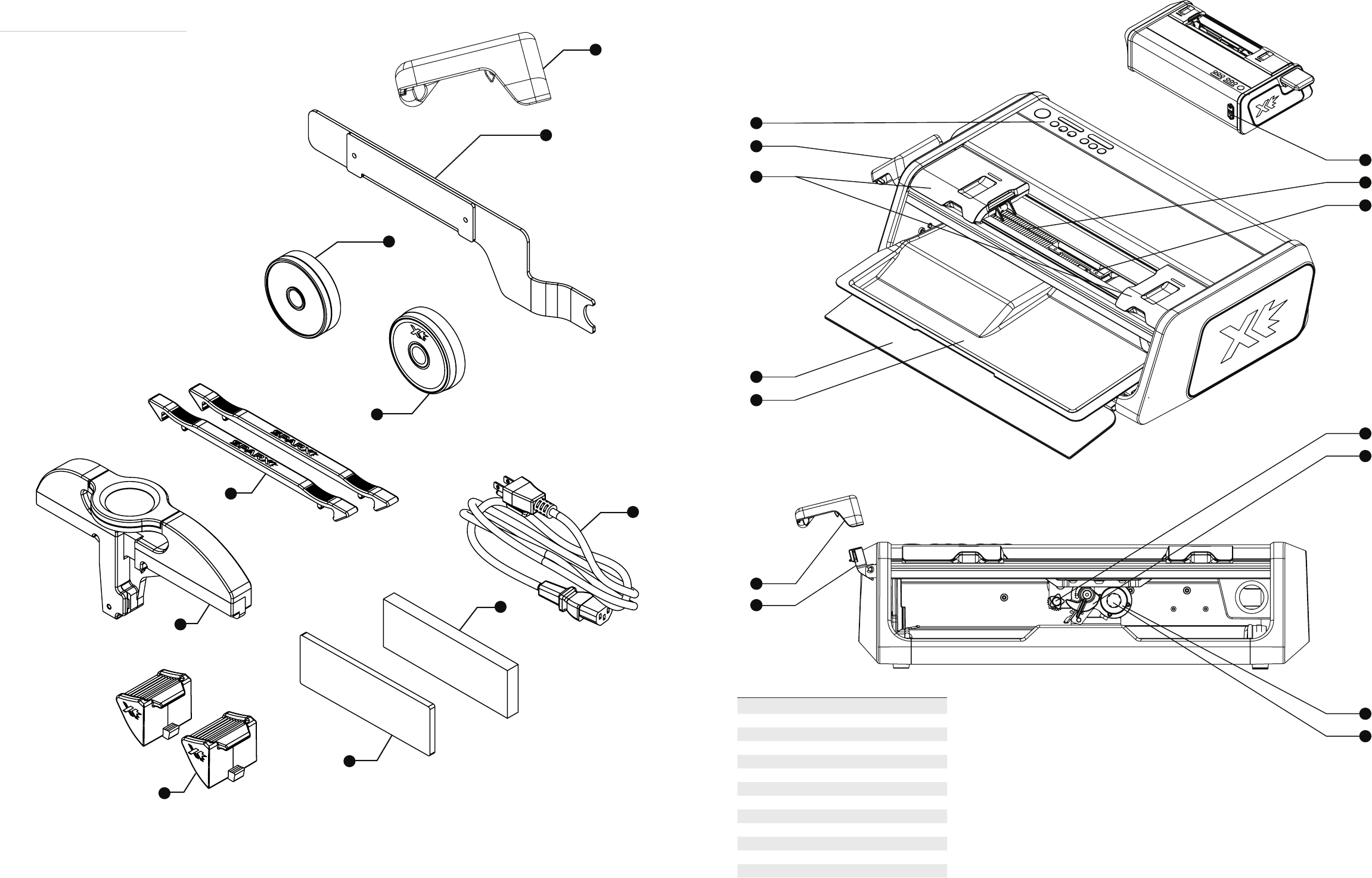
WHAT’S IN THE BOX
- Sharpener
1 - Clamp Lever
2 - Travel Guard
3 - Alignment Ring
4 - Grinding Ring
5 - Goalie Risers
6 - Power Cord
7 - Optical Alignment Tool
8- Honing Stone
9 - Leather Strop
10 - Youth Skate Adapters
A
B
C
D
E
F
G
H
I
J
K
L
M
N
PART DESCRIPTION
AKeypad
BClamp Lever
CProtective Slot Covers
DGlass Door
EDust Tray
FClamp Lever
GLever Dock
HPower Input Port - On/O Switch
IFilter
JSkate Clamp
KAlignment Adjustment Knob
LHeight Adjust Knob
MGrinding Ring Shaft
NThumb Nut
I
HE GD FC
A
B
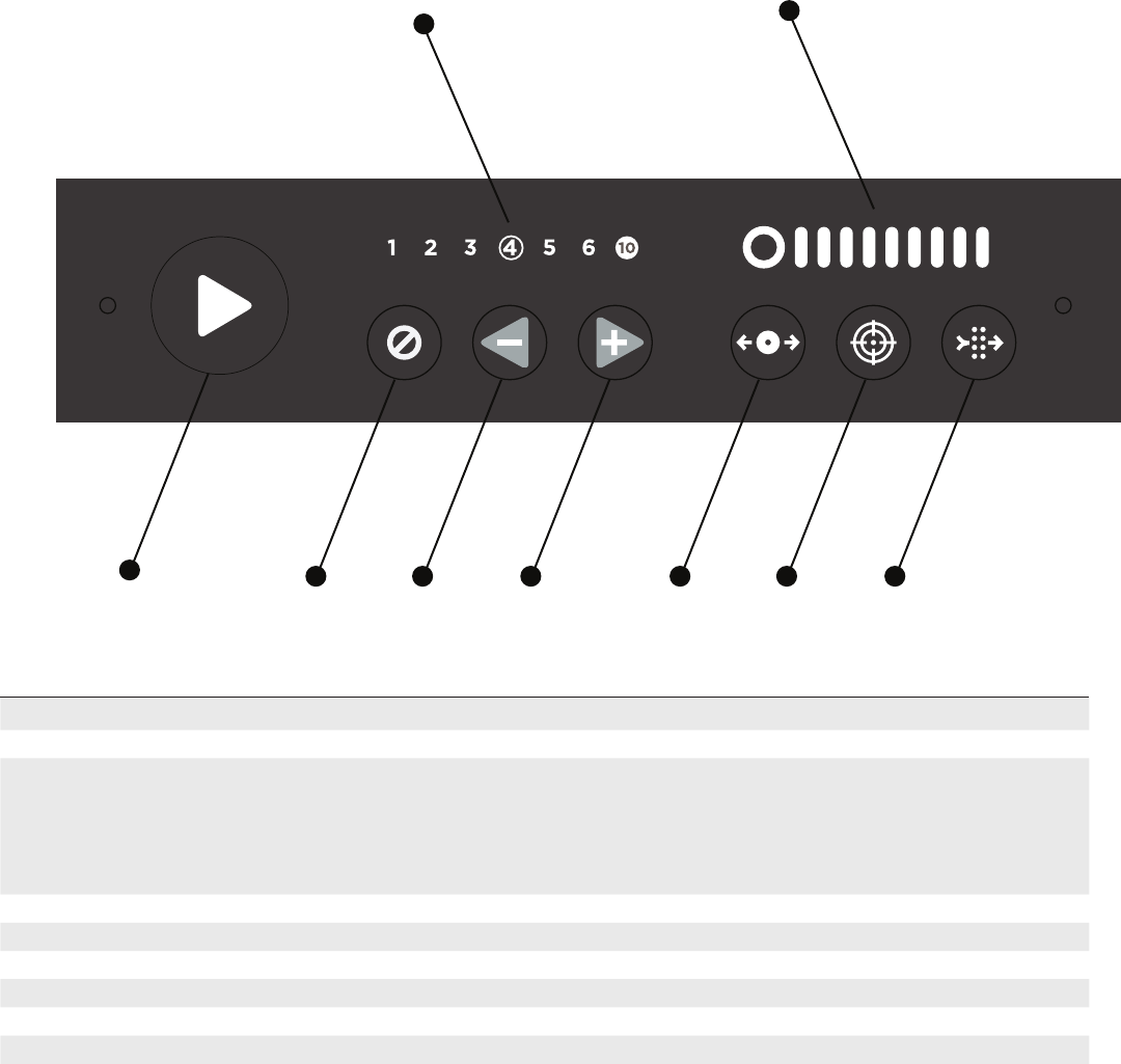
PART NAME DESCRIPTION
APlay Button Begins the sharpening cycle
BCycle Counter Displays the current number of cycles selected / displays error codes
CCancel/Error Button -Push one time to stop the carriage at conclusion of the current pass
-Push two times for an emergency stop; the motor will stop immediately
-When illuminated, the sharpener is in an error state. See Troubleshooting
-When illuminated in an error state, reset the sharpener by pressing one time
-Hold the button down for 2 seconds to recall a previous error code
DMinus Cycles/Move Left Button Subtracts cycles from the Cycle Counter/If in Move Mode, it moves the carriage left
EAdd Cycles/Move Right Button Adds cycles to the Cycle Counter/If in Move Mode, it moves the carriage right
FMove Button Press once to enter Move Mode to move the carriage
GCalibrate Button Press once to enter Calibration Mode
HAir Filter Button Indicates the filter needs to be replaced
IRing Life Indicator Indicates the grinding ring's life status
SHARPENER ASSEMBLY
To watch the video online, visit sparxhockey.com/assembly
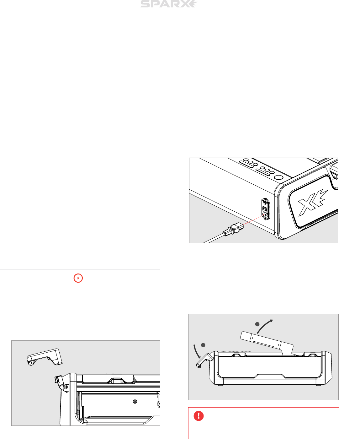
1 INSTALL THE CLAMP LEVER
Slide the Clamp Lever (A) onto the Lever Dock (B). Press the lever
down until it clicks into place. When engaged, the lever will lie at a
slight angle.
2 PLUG IN THE POWER CORD
3
Plug the Power Cord into the Power Input Port on the back of the
sharpener. Plug the other end into a wall outlet. Using the switch
on the Power Input Port, turn the sharpener on.
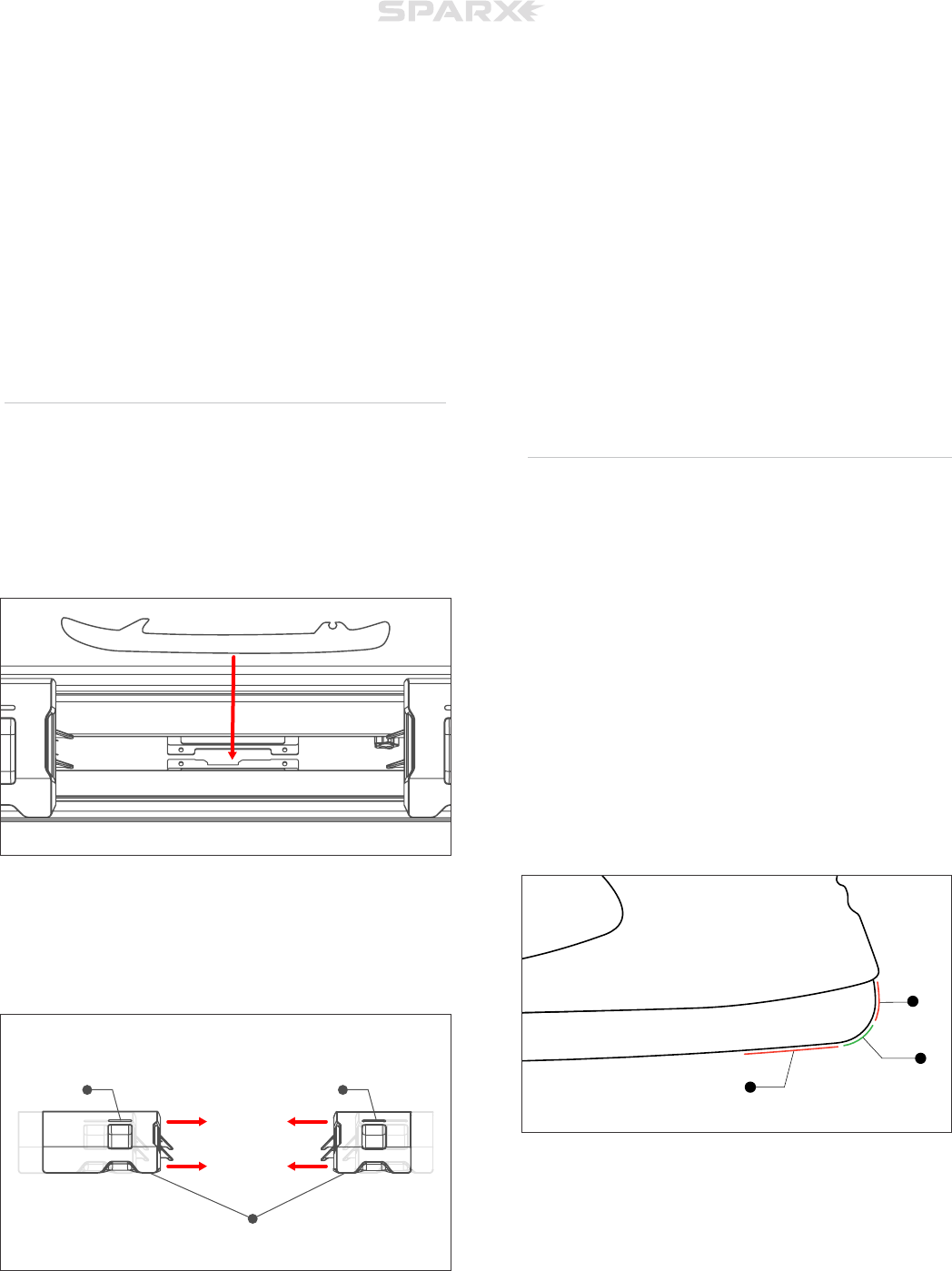
3 REMOVE THE TRAVEL GUARD
Open the Skate Clamp by pressing and holding down the Clamp
Lever. Remove the Travel Guard. Release the Clamp Lever to close
the Skate Clamps after removal.
Do not discard the Travel Guard. This guard is used to help keep
the components of the sharpener safe during travel. Damage
resulting from transport without the Travel Guard installed is not
covered by warranty.
SETUP
1
2
A
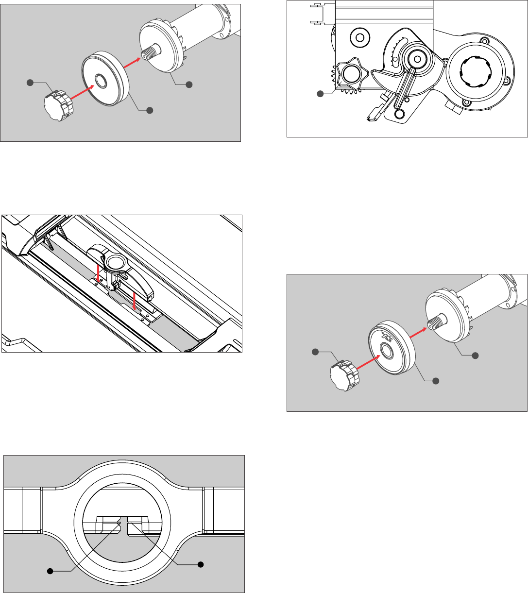
ALIGNMENT
1. Open the Glass Door. The carriage will automatically move into the
install position.
2. While holding the Grinding Ring Shaft (C), unscrew the Thumb
Nut (A). Slide the Alignment Ring (B) onto the Grinding Ring Shaft
(C), with the label facing out, and replace and tighten the Thumb Nut
until hand-tight. Close the Glass Door.
3. Press down on the Clamp Lever to open the Skate Clamp. Place
the Optical Alignment Tool (Sparx™ logo facing forward) into the
Skate Clamp. Place the Optical Alignment Tool into the slot and let
it fall into place. Release the Clamp Lever.
4. Press the c Calibrate Button to send the carriage to its alignment
position. When the carriage is in place, a tone will play and the case
will illuminate with blue LEDs.
5. Looking through the eyepiece of the Optical Alignment Tool, find
the indicator tab of the Alignment Tool (A). Ensure it aligns with the
notch on the Alignment Ring (B) as shown below.
If not aligned, follow step 6. If the indicator tab of the Alignment Tool
is in aligned with the notch on the Alignment Ring, move to step 7.
6. Open the Glass Door and locate the gray y Alignment Adjustment
Knob (A) inside of the sharpener. While looking through the Optical
Alignment Tool, turn the Alignment Adjustment Knob until the notch
on the Alignment Ring (right) lines up with the indicator tab of the
Alignment Tool (left), as shown below. Close the Glass Door when
aligned.
7. End Calibration Mode by pressing the c Calibrate Button.
8. Remove the Optical Alignment Tool by pressing and holding down
the Clamp Lever.
9. Open the Glass Door. The Carriage automatically moves into the
install position. Once the Carriage stops, unscrew the Thumb Nut and
remove the Alignment Ring.
10. Slide the Grinding Ring (B) (label facing forward) on the Grinding
Ring Shaft (C), label facing out, and replace and tighten the Thumb
Nut (A) until hand-tight. Close the Glass Door.
A
B
C
A
B
A
A
B
C
4
LOADING A SKATE
*For Goalie Skates, Youth Skates, and Sharpening New Steel, see the
end of this section.
1. Open the Skate Clamp by pressing and holding down the Clamp
Lever. With the skate toe facing left and the laces tucked into the
skate, set the skate into the Skate Clamp slot letting the plastic
blade holder rest on top of the clamps. Center the skate blade in the
Skate Clamps. Release the Clamp Lever.
2. With the skate clamped, move each Protective Slot Cover (A) in
towards the skate until they touch the blade holder and the Safety
Lights (B) extinguish.
ADJUSTING THE GRINDING
RING HEIGHT
For every skate sharpened, we must adjust the grinding ring’s
height. We’ll first introduce a few new concepts and then move
into the actual adjustment. As a reminder, this adjustment will be
performed for every new pair of skates sharpened.
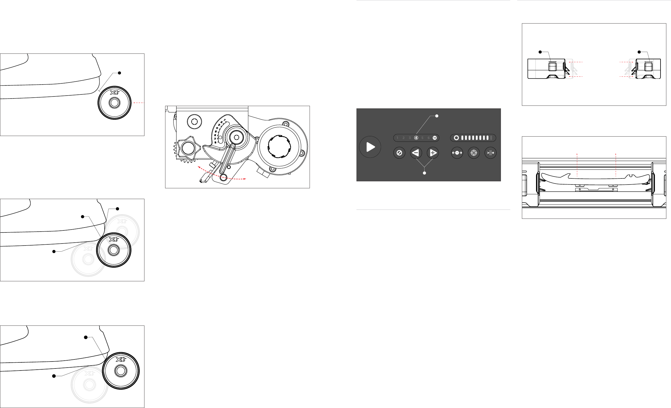
We want to first define an intersection zone where the vertical
face of the blade "B" meets the nearly horizontal face of the
blade "C". This zone can be a curved section of blade like that
shown in this figure or in some cases can be a point where
surfaces "B" and "C" meet.
When the intersection zone is a curved surface the grinding ring
can safely initially contact the blade anywhere in this region. We
typically recommend contacting in this zone at a 45 degree angle
(see Step X or Figure Y for more details). When the intersection
zone is a point, the first contact between the grinding ring and
the blade should be just below this point.
OPERATION
A
B
C
B B
A
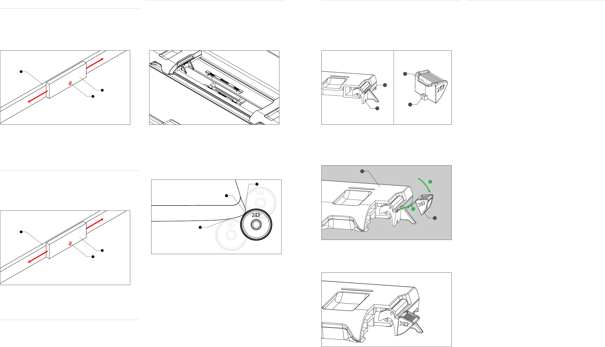
To check the Grinding Ring Height, we will enter Move Mode and
bring the Griding Ring left until we are about 1/4” from the blade (A).
This will allow us to see approximately where the first contact point
between ring and steel would be.
Below is an example of an intersection point (A) on a brand new
blade. We want our first contact point to be just below intersection
point (A). Point (B) is too high and point (C) is too low. For new
blades, we recommend starting at a height setting of 4 and moving
up until you hit the intersection point.
Below is an example of an intersection point (A) on a worn down
blade. We want our first contact point to be just below intersection
point (A). Point (C) is too low. For worn down blades, try starting with
a setting of 6 and moving up to hit your desired contact point.
1. Press the m Move Button on the keypad. This will set the Grinding Ring
into Move Mode and allow you to control its movement.
2. Using the l Left and r Right buttons on the keypad, move the
carriage to the left until it almost touches the heel of the skate blade.
4. Open the Glass Door. Using the red h Height Adjustment Knob, turn
left or right until the Grinding Ring is at a desired height. The knob is
labeled 1-8, with 8 being the highest setting for the Grinding Ring and 1
being the lowest setting.
5. Close the Glass Door. Once the Glass Door has been closed, using the
l Left and r Right Buttons, touch the Grinding Ring to the skate blade.
Inspect it’s contact point and be sure its in its desired position.
6. Press the m Move Button again to send the Grinding Ring back to its
home position.
B
C
A
A
C
B
A
A
UNLOADING SKATE
1. Move both Protective Slot Covers away from the skate. The safety light
on each cover will illuminate.
2. To open the Skate Clamp, press down the Clamp Lever. Remove the
skate from the Skate Clamp and release the Clamp Lever.
SELECTING CYCLE AMOUNT
When the sharpener moves the Grinding Ring out and back over the skate
blade once it is called a cycle.
Your Sparx™ Sharpener comes set to a standard four cycles with all
standard Radius Ring™ and FIRE Ring™ grinding rings automatically. We
recommend trying four cycles to start and moving higher or lower as
needed. Typically, we have found that four cycles will handle normal wear
and tear (and even small nicks) from one-five hours of skating in-between
sharpenings.
If choosing to adjust the cycle amount, use the l Left and r Right
buttons on the keypad to adjust the number of passes desired. The
number of passes selected will be illuminated on the Cycle Counter Bar
(A).
SHARPENING SKATES
Once you have loaded the skate properly, closed the safety guards, and
adjust the height of the Grinding Ring, you are ready to sharpen.
To cancel the cycles at any point during the sharpening, press the n
Cancel button once. This will send the Carriage back to its home position
at the end of its current pass.
1. Press the Play Button. Once the p Play button has been pressed, it will
change from white to blue and the sharpening process will begin.
Upon pressing play, the air fIlter fan and grinding motor will turn on. The
Cycle Counter will flash with the current cycle number until that pass (out
and in) is competed.
The sharpener will continue to run until all cycles have been performed.
At the completion of the final cycle, the end of sharpening is marked
by a 'cycle complete' tone and the case LEDs will turn green. The fan
will continue to run for an additional 30 seconds after the final cycle
completes.
ADDITIONAL CYCLES
If additional cycles are required, you can re-set the cycle count and press
the p Play button again.
A A
SHARPENING NEW STEEL
1. LOAD SKATE
Follow the instructions for Loading a Skate in the Operations section of
the manual.
2. ADJUST GRINDING RING HEIGHT
Follow the instructions for Adjust Grinding Ring Height in the Operations
section of in the manual.
3. SELECT 1 CYCLES
Using the l Left and r Right buttons on the keypad, select 1 on the
Cycle Counter.
3. PERFORM MARKER TEST
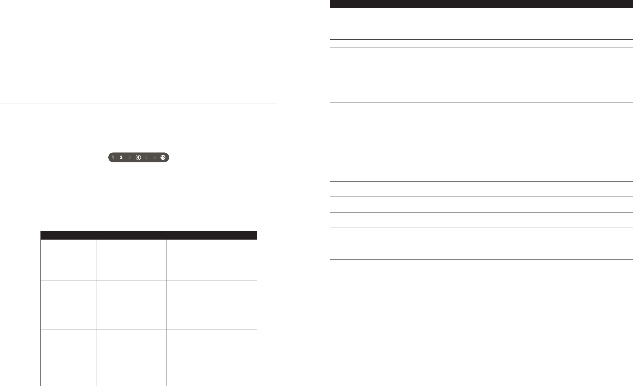
LOADING YOUTH SKATES
Before loading a youth skate of size 12 and below, Youth Skate Adapters
must be installed onto each Protective Slot Cover. On the adapter, locate
the Anchor Tab (A) on the top of the adapter and then the lower Anchor
Tab (B) on the bottom.
Below is a cross-sectioned Protective Slot Cover. Locate the recessed slot
(C) and the Tab Cut Out (D) on the Protective Slot Cover Switch.
1. Press the top Anchor Tab (A in figure above) into the recessed slot (C).
Once in, press down firmly on the top of the Youth Skate Adapter until
the bottom Anchor Tab clicks in place.
Below is an installed Youth Skate Adapter.
LOADING GOALIE SKATES
Before loading a goalie skate, you must first install the Goalie Risers onto
the Skate Clamp (one Goalie Riser on each side of the Skate Clamp). To
do this, locate the Anchor Slots on the Skate Clamp and align the Anchor
Pins to the slots. Once aligned, press down firmly until you feel Goalie
Risers snap into place.
Below is an example of an intersection point (A) on a goalie skate blade.
We want our first contact point to be just below intersection point (A).
Point (B) is too high and point (C) is too low.
EDGE DEBURRING WITH THE
SPARX HONING STONE
1. Press the Sparx™ Honing Stone (B) against the top side (closer to the
plastic blade holder) of the skate blade (A). Do not to put pressure on the
bottom of the stone closest to the blade edge. With light pressure, press
down on the lower side of the stone (C) and slowly run the stone back and
forth the length of the blade for four full passes.
2. Turn the skate over and repeat Step 1.
EDGE DEBURRING WITH THE
SPARX LEATHER STROP
1. Hold the skate, upside-down in one hand.
2. Press the Sparx Leather Strop against the edge of the blade at a 45
degree angle. Slowly run the strop up and down the length of the blade
for four full passes on each side of the edge.
2. Turn the skate over and repeat Step 1.
POWERING OFF
LOCATE THE POWER SWITCH
On the back of the sharpener, locate the Power Input Port and switch to
the o position.
A
B
C
B
D
A
C
B
1
2
A
B
A
C
B
A
C
ERROR MESSAGES
There are three types of errors encountered by the Sparx Sharpener which can interrupt operation. These error Types are: Startup,
Function Entry, and System Stop errors. Each error type is described in the table below along with information about how the user is
informed of the error.
For some error types, an Error Code is displayed on the Keypad’s Cycle Counter. The Troubleshooting Table below suggests possible
corrective actions to resolve the error.
If the Error Code was only temporarily displayed or the user wishes to cycle through previous Error Codes, hold down the Cancel/Error
button for 2 seconds until a beep is heard (button initially emits error buzz when pressed). Once the beep is heard, the most recent
Error Code is displayed and pressing the Move Left and Move Right buttons will cycle through previous Error Codes
7
TROUBLESHOOTING
ERROR CODE POSSIBLE CAUSE CORRECTIVE ACTION
1 - 2 - 4 Glass Door open. Close Glass Door.
1 - 2 - 5 Excessive Glass Door opening during calibration. Attempt calibration again while leaving Glass Door closed until
Carriage stops at calibration location.
1 - 2 -6 Dust Tray missing. Confirm that Dust Tray is correctly installed.
1 - 2 - 10 Air Filter missing. Air Filter Missing.
1 - 3 - 10 Attempted to start calibration routine with skate or
Grinding Ring installed.
Adjust skate and protective slot covers until contact is made
between Protective Slot Covers and both ends of the installed skate.
LEDs on Protective Slot Covers should be extinguished.
Use Youth Skate Adapters if skate is too small to make contact with
both Protective Slot Covers.
1 - 4 - 5 Pressed the p Play button in Calibration Mode. Exit Calibration Mode prior to pressing the p Play button.
1 - 4 - 6 Pressed the p Play button in Move Mode. Exit Move Mode prior to pressing the p Play button.
1 - 5 - 10 Left Protective Slot Cover Disengaged.
Adjust skate and protective slot covers until contact is made
between Protective Slot Covers and both ends of the installed skate.
LEDs on Protective Slot Covers should be extinguished.
Use Youth Skate Adapters if skate is too small to make contact with
both Protective Slot Covers.
1 - 6 - 10 Right Protective Slot Cover Disengaged.
Adjust skate and protective slot covers until contact is made
between Protective Slot Covers and both ends of the installed skate.
LEDs on Protective Slot Covers should be extinguished.
Use Youth Skate Adapters if skate is too small to make contact with
both Protective Slot Covers.
2 - 3 - 6 Sharpener failed to detect skate. Ensure that skate is installed in Skate Clamp correctly and that
Grinding Ring height is adjusted properly.
2 - 4 - 10 Grinding Ring empty. Install a valid Grinding Ring.
2 - 5 - 6 Grinding Ring not found. Install a valid Grinding Ring.
2 - 5 - 10 Grinding Ring read incomplete. Repeat process and allow extra time between steps. If this doesn’t
resolve problem, replace Grinding Ring.
2 - 6 - 10 Grinding Ring read error. Install a valid Grinding Ring.
3 - 5 - 10 Grinding Motor over-current. Confirm that Grinding Ring height is adjusted properly and nothing
is obstructing the Grinding Ring.
3 - 6 - 10 Translation Error - Limit undetected. Confirm that the Carriage is not obstructed.
ERROR TYPE DESCRIPTION DISPLAY METHOD
I: Startup Errors encountered by the
system during startup.
Displayed through the User Interface (e.g.
flashing LEDs at the area of concern, for
example the Protective Slot Cover LEDs)
No Error Code is displayed for this type.
II: Function Entry
Errors that prevent the user
from entering into a function
(e.g. sharpening or calibration).
Displayed through the User Interface (e.g.
flashing LEDs at the area of concern, for
example the Slot Cover LEDs)
&
Error Code temporarily displayed on the
keypad’s Cycle Counter. See below.
III: System Stop
Errors that cause the machine
to exit out of a function be-
cause of safety concerns or to
prevent machine damage.
Error Code that caused the machine to
be stopped is displayed on the keypad’s
Cycle Counter. See below.
All functionality is disabled until the user
acknowledges the error by pressing the
n Cancel button.
In the event that a error cannot be resolved, please contact customer support at Sparx Hockey.
SPARX HOCKEY CUSTOMER SUPPORT
help@sparxhockey.com (fastest response)
1-800 -SPARX HQ
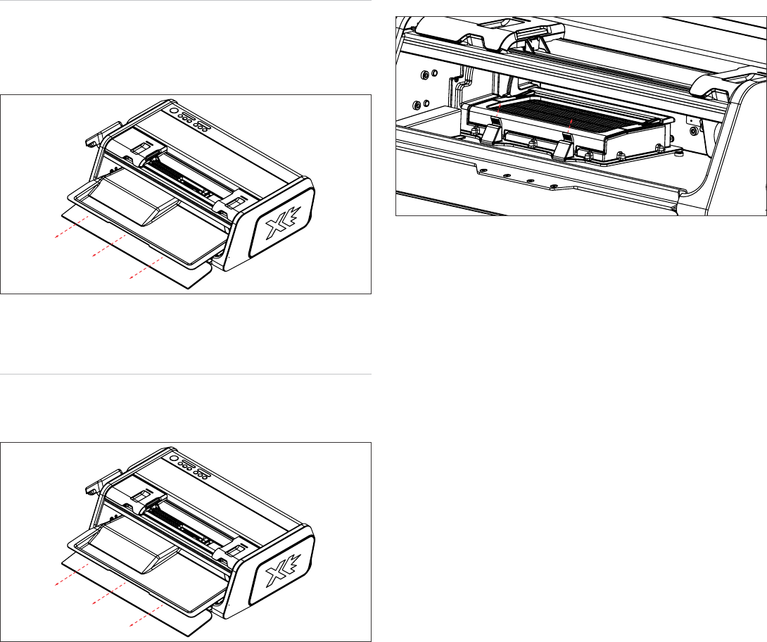
EMPTYING DUST TRAY
When the Dust Tray is full and before moving or traveling with the Sparx™
Sharpener, empty the Dust Tray.
1. Open the Glass Door. Slide out the Dust Tray and dispose of the steel
shavings.
2. Slide the Dust Tray back into the machine. Close Glass Door.
CHANGE AIR FILTER
The Air Filter will last 200 sharpenings. After that, we can no longer
ensure that your filtering quality will remain at our high standards. The f
Air Filter button will light up reminding you to order a replacement filter.
1. Open the Glass Door. Slide out the Dust Tray.
2. Push up on the two tab locks on the filter housing. Open the top lid of
the housing until it clicks into the open position. Remove the filter.
3. Push up on the two tab locks on the filter housing. Open the top lid of
the housing until it clicks into the open position. Remove filter.
Once your filter has been replaced, hold down the f Air Filter button for
two second to reset the system.
8
MAINTENANCE
LIMITED ONE YEAR PRODUCT WARRANTY
Velasa Sports, Inc. (“Velasa Sports”) warrants that, under normal use and
provided that you have followed our reasonable care instructions, your
Sparx™ Product will be free from defects in materials and workmanship
for a period of one (1) year from the date of purchase from Velasa Sports
or an authorized Velasa Sports reseller or partner. Your exclusive remedy
and our sole obligation is to repair or replace any Product that Velasa
Sports reasonably determines does not comply with this warranty or, at
our sole discretion, to accept return of such Product and refund to you the
price paid therefor.
Products that have been repaired or replaced hereunder shall be covered
by this warranty for the longer of thirty (30) days after being shipped
back to you or the remainder of the original 1-year warranty period. Any
Product or component that is replaced becomes the sole property Velasa
Sports.
HOW TO MAKE A WARRANTY CLAIM
If you experience any problems with your Sparx™ Product, please
contact Customer Service at help@sparxhockey.com. Upon confirmation
and approval of your warranty claim, we will assign a return material
authorization number ("RMA"). At your risk and expense, you must deliver
the nonconforming Product (with prominent indication of the RMA) to
Velasa Sports or its designated repair center. Products returned without
an RMA shall not be aorded warranty service, and you shall be liable
for all costs and expenses incurred by us in connection with servicing the
unauthorized return.
EXCLUSIONS
All claims under this limited warranty must be made during the applicable
warranty period.
This limited warranty shall be void and not apply as to any Product that
was (a)used, handled, operated, maintained or stored improperly, or
in any manner not in accord with our documentation, instructions or
recommendations, (b)repaired, altered or modified by anyone other
than Velasa Sports or its authorized agents or (c)used with parts or
accessories not supplied by Velasa Sports.
SPARX™ PRODUCTS ARE NOT WARRANTED FOR COMMERCIAL OR
RENTAL USE. Velasa Sports' limited warranty does not include coverage
or liability for the loss of or damage to any Ice Skates with respect to
which the Sparx™ Product was used.
DISCLAIMERS
EXCEPT AS EXPRESSLY SPECIFIED HEREIN, ALL SPARX™ PRODUCTS
ARE PROVIDED "AS IS" WITHOUT REPRESENTATION OR WARRANTY
OF ANY KIND. VELASA SPORTS DOES NOT WARRANT THAT THE
SPARX™ PRODUCTS WILL MEET YOUR REQUIREMENTS, OR THAT
THEIR OPERATION WILL BE ERROR-FREE. FOR ITSELF AND ITS
LICENSORS, VELASA SPORTS HEREBY DISCLAIMS ALL OTHER
REPRESENTATIONS AND WARRANTIES, EXPRESS OR IMPLIED,
ORAL OR WRITTEN, INCLUDING WITHOUT LIMITATION, ALL IMPLIED
WARRANTIES OF TITLE, NON-INFRINGEMENT, INTEGRATION,
MERCHANTABILITY OR FITNESS FOR ANY PARTICULAR PURPOSE.
OTHER TERMS
This warranty gives you specific legal rights, and you may also have other
rights which vary from state to state.
Your use of this Site and the Services (including your purchase of Sparx™
Products) are governed by our Terms of Service, which are available at
https://www.sparxhockey.com/pages/terms-services. Capitalized terms
used herein without definition will have the same meanings as defined in
the Terms of Service.
9
WARRANTY

Sparx™ Hockey 30 Sudbury Rd. Acton, MA 01720 USA
Copyright © 2016 Velasa Sports Inc.
All Rights Reserved