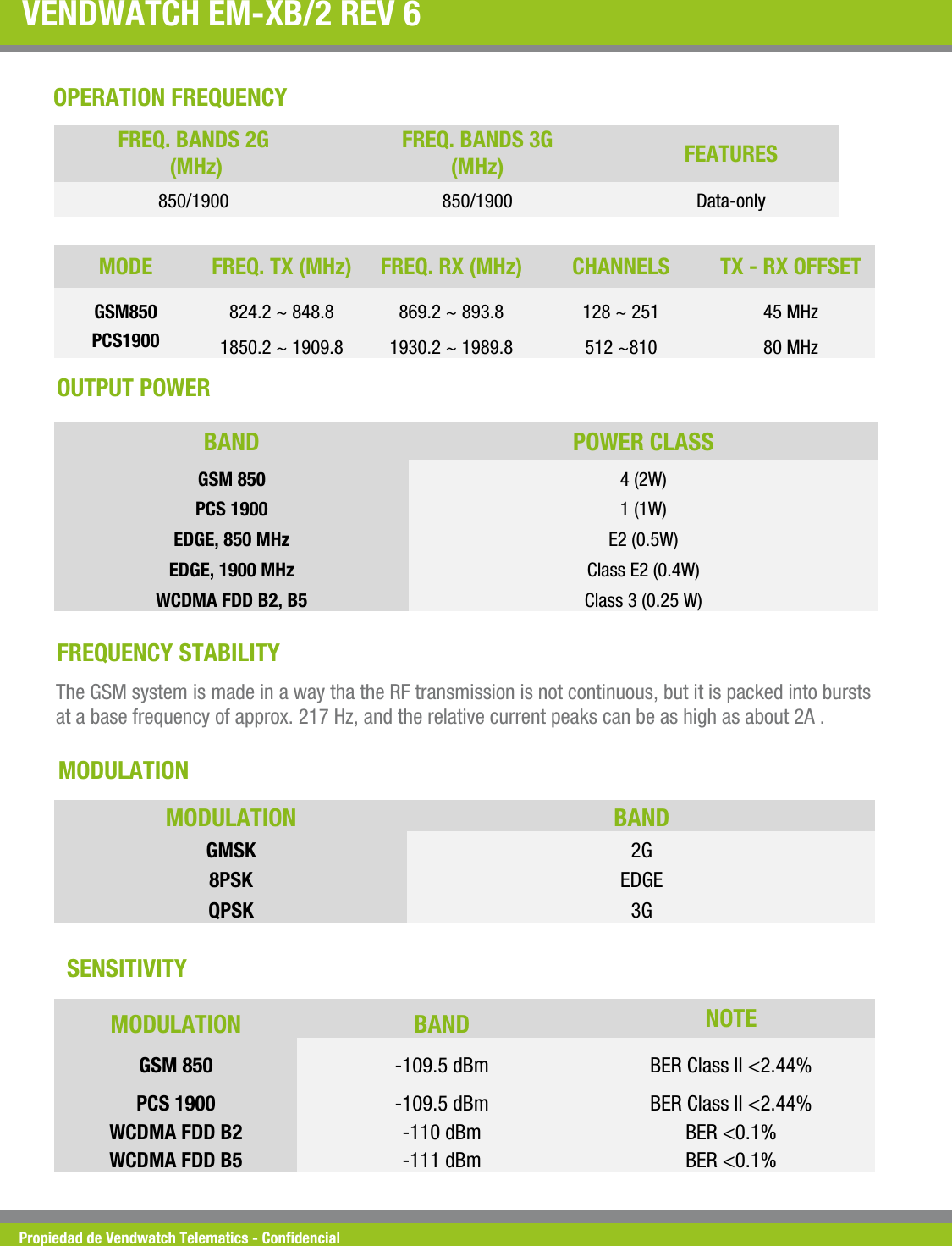
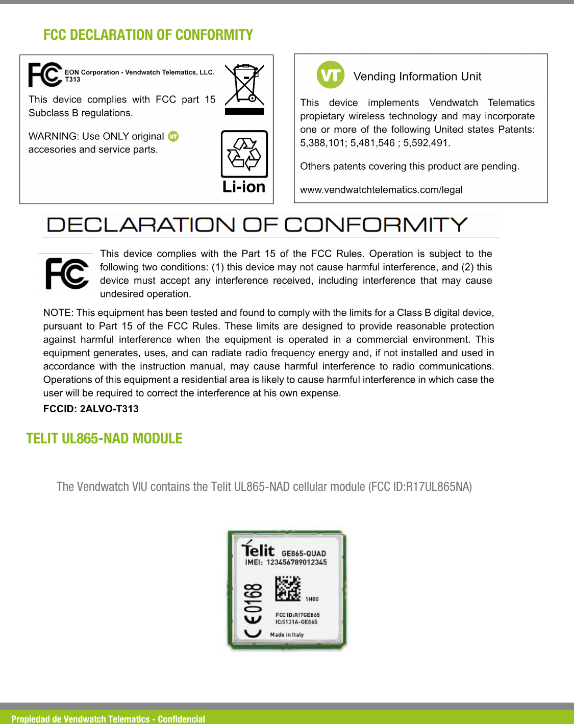
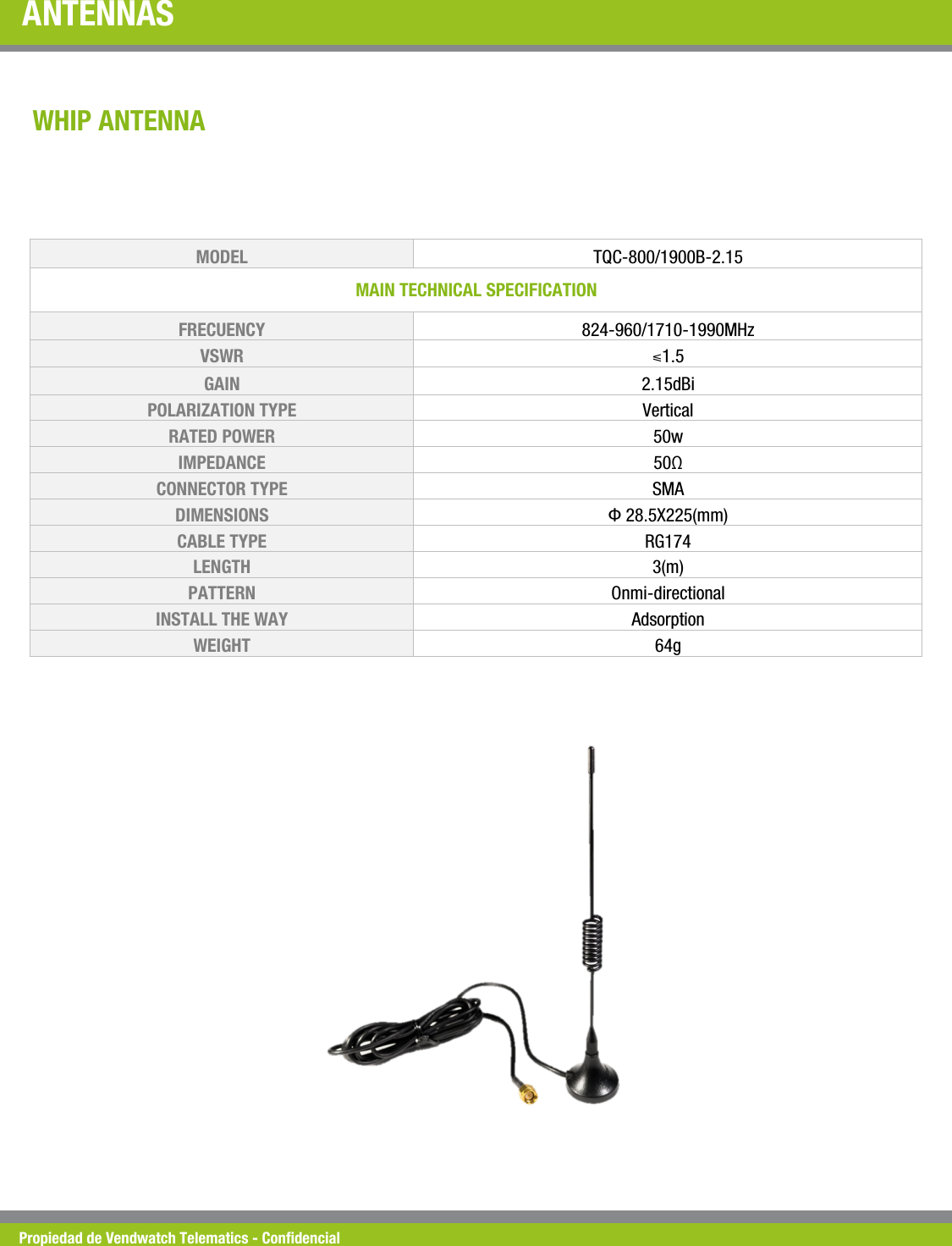
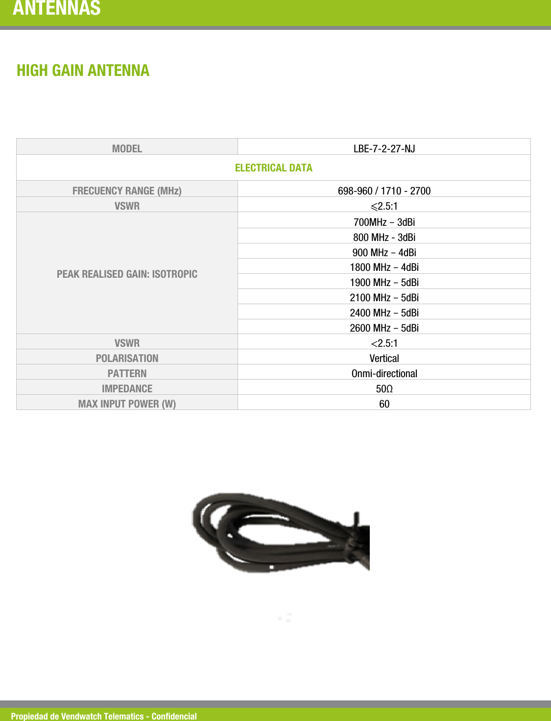
Vendwatch Telematics T313 Vending machine wireless management system User Manual

Vendwatch Telematics, LLC Vending machine wireless management system

User Manual

Propiedad de Vendwatch Telematics - Condencial VM CONNECT T313 USER MANUAL  Version 0.07
Propiedad de Vendwatch Telematics - Condencial + DATE  VERSION  CHANGES MARCH 12, 2016   0.01 Initial Draft MARCH 18, 2016   0.02 Installation Feedback APRIL 12, 2016   0.03 Added EPay display status JUNE 1, 2016   0.04 Swapped the mounting brackets solely to magnets JUNE 3, 2016   0.05 Replaced picture of device with magnet-captive clips JUNE 4, 2016   0.06 Wiring Diagram, Door Switch “NO”and “NC” explanation JUNE 15, 2016  0.07 Improve Extension DWG
Propiedad de Vendwatch Telematics - Condencial PURPOSE The sections that follow describes how to install the Vendwatch Telematics (VT) VendMine (VM) Connect T313 Telemetry Device in Vending Machines using general guidelines applicable to a universal principle of operation. Other documents would detail specic mounting location and cable routing for the various models available in the market from different manufacturers. Before proceeding with the installation verify that the VM IS NOT POWERED and Alternating Current (AC) or High Tension Voltage is not connected to the vending machine.
Propiedad de Vendwatch Telematics - Condencial UNPACKING THE UNIT Each container includes the T313 Telemetry Device, the telemetry antenna and the accessories kit. Clips to  mount the enclosure and splice connectors to connect the door switch are found inside the kit amongst other items necessary to complete the professional appearance of the installation.
Propiedad de Vendwatch Telematics - Condencial MOUNTING THE DEVICE VM come in a variety of versions, models and their respective revisions. Two magnet-captive mounting clips, included in the kit, provide exibility of installation; the desired location is accomplished by inserting the clips right-to-left or left-to-right (see picture below), allowing the unit to be attached to any internal VM unused wall. The units is intended to be mounted with the LEDs facing the installer and the cables hanging to the oor. LEFT MOUNT RIGHT MOUNT
Propiedad de Vendwatch Telematics - Condencial CONNECTING THE CABLES The next step after the the unit is secured in the VM chassis is to connect the cables to their respective interfaces. The T313 Telemetry device has 6 distinctive cables connecting the unit to the VM controller Direct EXchange (DEX) port, the Electronic Payment (EPay) System, the Multi Drop Bus (MDB) serving the legacy payment system, the Door Switch and Temperature Sensors and the antenna cable.  DEX EPAY MDB DSS TCS ANT From left to right the function of the cables protruding from the T313 Telemetry Device are: DEX, EPay, MDB, Door Switch Sensors (DSS), Temperature Control Sensors (TCS) and the Antenna.
Propiedad de Vendwatch Telematics - Condencial MOUNTING THE ANTENNA The External Antenna will be mounted on top right side of the door and on the same side of the machine where the T303 Telemetry Device is installed. To do this, you will need to drill a 5/8 hole using the conical drill bit as shown. Once drilling is completed, remove the hex nut from the antenna and insert the cable into the hole from the outside, now tighten the nut from the inside of the machine. Connect the Antenna to the corresponding connector in the VM Connect Device.
Propiedad de Vendwatch Telematics - Condencial CONNECTING THE DEX CABLE The Telemetry T313 Device requests Sales, Health and Status of the VM by connecting to the Direct EXchange (DEX) connector. The VM Controller (VMC), the intelligence behind the VM functionality, provides a DEX interface connector, ¼” phone jack, in some models solder directly on the board and other models as a dongle. Find the DEX ¼” phone jack and connect the T313 Telemetry Device ¼” phone plug into it as illustrated below. The cable provides a spare ¼” phone jack to facilitate connecting additional devices on the DEX port.
Propiedad de Vendwatch Telematics - Condencial MOUNTING THE EPAY UNIT The Electronic Payment (EPay) unit should be mounted on the VM using, as a minimum, two of the mounting metal inserts in the back of the EPay unit. When necessary, an additional perforation of the chassis is required to accommodate proper routing of the EPay interface cable.
Propiedad de Vendwatch Telematics - Condencial CONNECTING THE EPAY UNIT Find the EPay cable on the T313 Telemetry Device and connect the cables together. Additional 1 meter extension cables can be purchased if the distance between the T313 and the EPay devices exceeds 1.5 meters. Upon powering up the unit the EPay unit will display “Reader Currently Disabled”, once initialized the legend changes to “Tap or Swipe Card t Vend”; during Dex reads, the legend would be “Processing Data Back Soon”.
Propiedad de Vendwatch Telematics - Condencial CONNECTING THE MDB The VMC provides power and controls the legacy payment system by allowing multiple devices to connect to the MDB bus. The installation would require to nd the last device on the MDB bus and connect the T313 Telemetry Device at the end. If the last device on the bus does not have a spare connector, the installation would require to disconnect the last device on the bus and connect the T313 Telemetry Device as second to last on the bus as illustrated below.
Propiedad de Vendwatch Telematics - Condencial CONNECTING THE DOOR SWITCH The cable used to connect the device to the VM door switch has 6 wires providing 3 separate functions; each using dedicated color wires based on VM instrumentation as follows: • NC Pair: RED/ORANGE • NO Pair: BROWN/BLACK • VT NO Switch Kit available for sale: GREEN/YELLOW The VM is equipped with a door switch connected to the VMC; typically, one of the poles is connected to what’s universally referred as common (return, ground or shield); the other pole is commonly referred as the “hot wire” and reects the state of the door. The door switch is determined to be in a “NORMAL” state when the plunger “IS NOT” retracted hence the term Normally Closed (NC) or Normally Open (NO).
Propiedad de Vendwatch Telematics - Condencial CONNECTING THE DOOR SWITCH The switch is wired one of two ways, Poles are Normally Open (NO) or Poles are Normally Closed (NC). When the door is open and the switch plunger is fully extended, the “NO” POLE and the “COMMON” POLE ARE NOT making contact while the “NC” POLE and the “COMMON” POLE  ARE making contact with each other.  To facilitate the integration of the VM door switch with the Telemetry device, a test tool universally known as a continuity tester would be used. The tool indicates when two points make contact when a led or a buzzer, instrumented in the tool, emanates light or sound as depicted below. OPEN CIRCUIT CLOSED CIRCUIT
Propiedad de Vendwatch Telematics - Condencial FINDING THE COMMON POLE  Connect the continuity test tool alligator clip to the shield of the Dex connector as shown  Locate the switch, it must have two wired poles, however it may have a third pole that would not be wired. After locating the door switch, use the tip of the the continuity tester tool to make contact with one of the wired poles. If the light of the Continuity Tester Tool turns ON, press and release the Door Switch button, if the light is still ON no matter what state the Door Switch is in, then you have found the Common Pole. The Dex port and the Common Pole are both ground, so stay connected to the Dex port  Switch in Normal state (Button Extended) YES  YES Touching Wired Pole !YES  YES Light/Sound ON !NO  YES Switch Type !NO (Normally Open)  NC (Normally Closed)  Wire Pair Color to be used !Brown/Black  Red/Orange
Propiedad de Vendwatch Telematics - Condencial FINDING THE COMMON POLE  Now make contact with the the other pole to validate the switch model and  the poles connectivity. DOOR SWITCH  LIGHT / SOUND  POLE TYPE  SWITCH TYPE Extended or Pressed  YES  Common  Unknown Extended  NO  NO  Normally Open  Pressed  YES  NO  Normally Open Extended  YES  NC  Normally Closed Two distinctive connecting options, “NO” or “NC” are available based on the results of the continuity test.
Propiedad de Vendwatch Telematics - Condencial CONNECTING THE T313 TELEMETRY WITH A NORMALLY CLOSED (NC) DOOR SWITCH Following the results of the test above, cut the wire connected to the “NC” pole of switch.  1. Locate the RED Wire in the Door Switch Cable of the T313 Telemetry and splice it with the wire still connected to the switch using one of the UY2 connector. 2. Locate the ORANGE Wire in the Door Switch Cable of the T313 Telemetry and splice it with the other side of the previously cut wire using one of the UY2 connector. This wire is now connected to the VMC controller.
Propiedad de Vendwatch Telematics - Condencial CONNECTING THE T313 TELEMETRY WITH A NORMALLY OPEN (NO) DOOR SWITCH Following the results of the test above, cut the wire connected to “NO” pole of the switch.  1. Locate the BLACK Wire in the Door Switch Cable of the T313 Telemetry and splice it with the wire still connected to the switch using one of the UY2 connector. 2. Locate the BROWN Wire in the Door Switch Cable of the T313 Telemetry and splice it with the other side of the previously cut wire using one of the UY2 connector. This wire is now connected to the VMC controller.
Propiedad de Vendwatch Telematics - Condencial ADDING DOOR SWITCH EXTENSION CABLE  When the Door Switch is installed far from the VM Controller, an extension will be provided with two wires, BLACK and RED.  To connect the extension to a “NO” switch, using a Wire Connector join the T310 Black wire with the extension’s Black wire and the T310 Brown wire with the extension’s Red wire, now the Black and Red wires will be available. Cut the “NO” wire and join the Black one to the Door Switch and the Red one to the VMC. NORMALLY OPEN (NO) WIRING DIAGRAM WITH EXTENSION T31x Coffee Black   VMC   Red Black         To connect the extension to a “NC” switch, using a Wire Connector join the T310 Red wire with the extension’s Red wire and the T310 Orange wire with the extension’s Black wire, now the Black and Red wires will be available. Cut the “NC” wire and join the Red one to the Door Switch and the Black one to the VMC. T31x Normally Closed (NC) wiring diagram with extension Red Orange   VMC   Red Black
Propiedad de Vendwatch Telematics - Condencial THE DEVICE INDICATORS Power led Telemetry led  Status led  ESN number  Rell button VT LOGO  Cong SW Model number The device has icons on the front of the device indicating different functions for ease of installation. The label at the front top of the unit contains the Model of the unit, the label at the front bottom of the unit houses the Electronic Serial Number (ESN). The “GEAR”         icon illustrate the location of the conguration switch; a special key will be provided to qualied technicians who have been trained in the art of troubleshooting the device. The “TOUCH”           icon illustrate the location of the “Rell Button”. By placing a nger, preferably the thumb, over the icon the device would determined that a button has been depressed. The behaviour of the device’s LEDs will be described in the following sections.
Propiedad de Vendwatch Telematics - Condencial THE BEHAVIOUR OF THE POWER LED STATE ILLUMINATION DESCRIPTION On  Solid Green  VM is powered on AND the device is connected to MDB Off  Off  VM is powered off OR the device is disconnected from the MDB; if the Telemetry or Status LED are illuminated solid or blinking, it is running on battery. THE  BEHAVIOUR OF  THE TELEMETRY LED STATE ILLUMINATION DESCRIPTION Radio On  Solid Green  Power was applied to the Telemetry module Radio Off  Off  Power was removed from the Telemetry module Radio Training  Green, On 50%  Radio is searching for available networks Radio Connected  Green, On 87%  Radio is connected to selected network THE BEHAVIOUR OF THE STATUS LED STATE ILLUMINATION DESCRIPTION Off  Off  The device is off Booting Up  Green, On 50%  The device is getting up to the normal state Normal  Green, Solid  The device is in normal state Programing  Purple, Blinking 50%  The device is being programmed Alert  Orange, Solid  The device has detected issues Handheld  Blue, Solid  The device is connected to VM Guide/Care Battery  Red, Blinking 50%  The device is running on battery Rell  White, Blinking 50%  The device is reading DEX Mfg Testing  Purple, Blinking 50%  The device is running manufacturing test
Propiedad de Vendwatch Telematics - Condencial VENDWATCH EM-XB/2 REV 6  MODE   FREQ. TX (MHz)  FREQ. RX (MHz)  CHANNELS  TX - RX OFFSET GSM850  824.2 ~ 848.8  869.2 ~ 893.8  128 ~ 251   45 MHz PCS1900  1850.2 ~ 1909.8  1930.2 ~ 1989.8  512 ~810  80 MHz OPERATION FREQUENCY FREQ. BANDS 2G  (MHz) FREQ. BANDS 3G  (MHz)  FEATURES 850/1900  850/1900  Data-only OUTPUT POWER BAND   POWER CLASS GSM 850  4 (2W) PCS 1900  1 (1W) EDGE, 850 MHz  E2 (0.5W) EDGE, 1900 MHz  Class E2 (0.4W) WCDMA FDD B2, B5  Class 3 (0.25 W) FREQUENCY STABILITY  The GSM system is made in a way tha the RF transmission is not continuous, but it is packed into bursts at a base frequency of approx. 217 Hz, and the relative current peaks can be as high as about 2A .  MODULATION  MODULATION  BAND GMSK  2G 8PSK  EDGE QPSK  3G MODULATION  BAND  NOTE GSM 850  -109.5 dBm  BER Class II <2.44% PCS 1900  -109.5 dBm  BER Class II <2.44% WCDMA FDD B2  -110 dBm  BER <0.1% WCDMA FDD B5  -111 dBm  BER <0.1% SENSITIVITY
Propiedad de Vendwatch Telematics - Condencial TELIT UL865-NAD MODULE The Vendwatch VIU contains the Telit UL865-NAD cellular module (FCC ID:R17UL865NA) FCC DECLARATION OF CONFORMITY
Propiedad de Vendwatch Telematics - Condencial ANTENNAS  WHIP ANTENNA MODEL   TQC-800/1900B-2.15 MAIN TECHNICAL SPECIFICATION  FRECUENCY  824-960/1710-1990MHz VSWR  ⩽1.5 GAIN  2.15dBi POLARIZATION TYPE  Vertical  RATED POWER   50w IMPEDANCE   50Ω CONNECTOR TYPE  SMA DIMENSIONS   Φ 28.5X225(mm) CABLE TYPE  RG174 LENGTH  3(m) PATTERN  Onmi-directional INSTALL THE WAY   Adsorption WEIGHT  64g
Propiedad de Vendwatch Telematics - Condencial ANTENNAS MODEL   LBE-7-2-27-NJ ELECTRICAL DATA  FRECUENCY RANGE (MHz)  698-960 / 1710 - 2700 VSWR  ⩽2.5:1 PEAK REALISED GAIN: ISOTROPIC 700MHz – 3dBi 800 MHz - 3dBi 900 MHz – 4dBi 1800 MHz – 4dBi 1900 MHz – 5dBi 2100 MHz – 5dBi 2400 MHz – 5dBi 2600 MHz – 5dBi VSWR  <2.5:1 POLARISATION  Vertical PATTERN  Onmi-directional IMPEDANCE  50Ω MAX INPUT POWER (W)  60 HIGH GAIN ANTENNA

Navigation menu