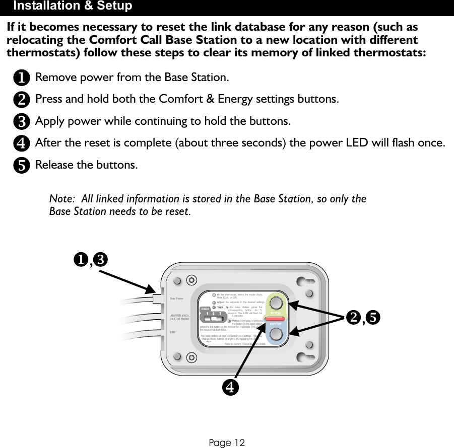
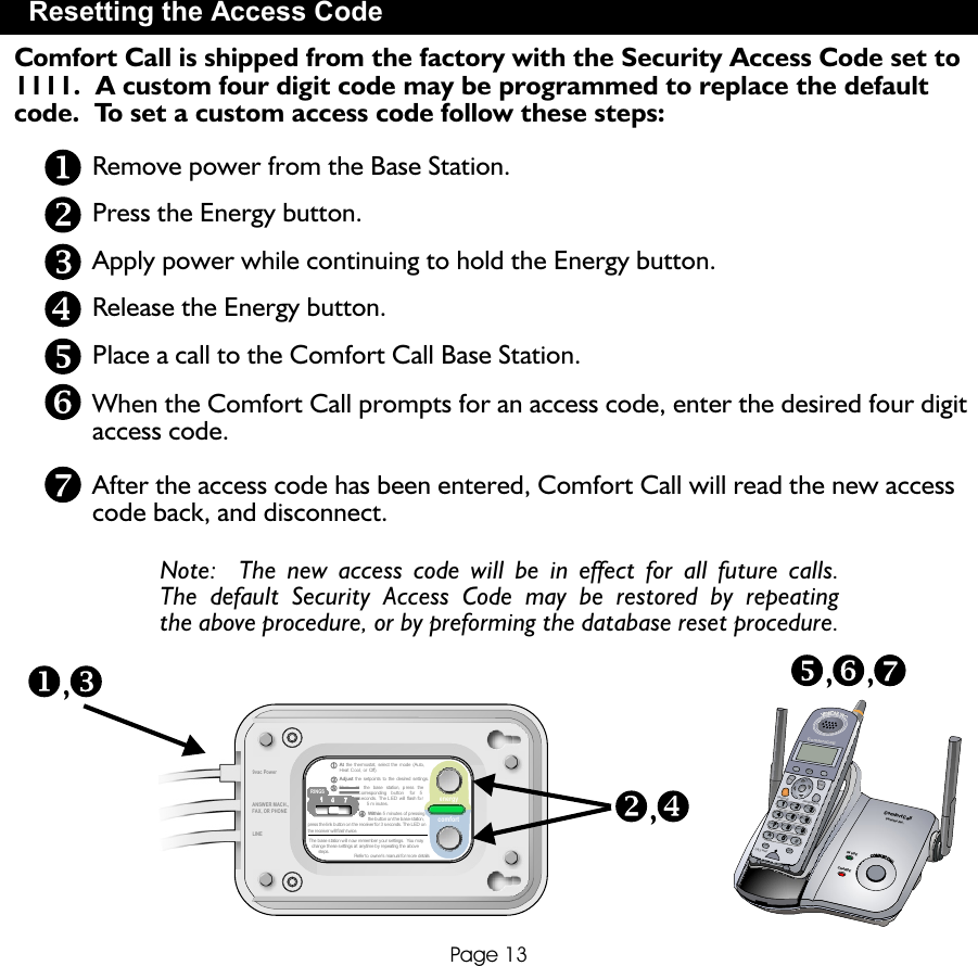
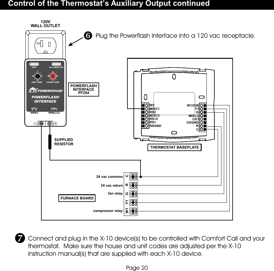
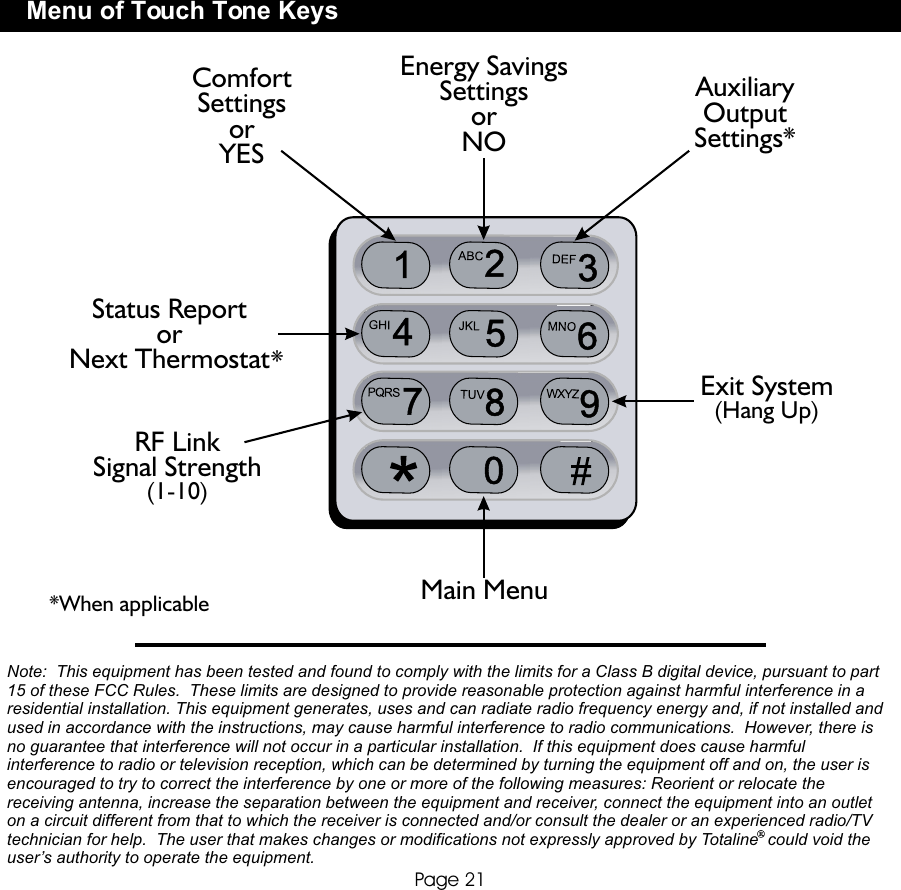
Venstar BASE1 Controller Base for Thermostat User Manual Manual Totaline P374 0433 Rev 2

Venstar Inc Controller Base for Thermostat Manual Totaline P374 0433 Rev 2

Manual

Replacement Components Division      Carrier Corporation 02/07Complete Control fromBASE STATION& RF WIRELESSMODULEBASE STATION& RF WIRELESSMODULEBASE STATION& RF WIRELESS MODULEBASE STATION& RF WIRELESS MODULECOMFORT      CALLCOMFORT      CALLCOMFORT      CALLCOMFORT      CALLOWNER’S MANUALOWNER’S MANUALCOMFORTCALL SYSTEMP/N P374-0433COMFORTCALL SYSTEMP/N P374-0433TOTALINECompatible with thermostat models: P374-1700, P374-1800, P374-1900,P374-2700, P374-2800, & P374-2900for a complete list contact RCD
OverviewLocation of Controls, Indicators& ConnectionsTable of ContentsInstallation & SetupResetting the Access CodeOperationLink up to 4 Thermostats to 1 Base StationControl of the Thermostat’s Auxiliary OutputMenu of Touch Tone KeysWarrantyPage 1P/N P374-0433Replacement Components Division      Carrier Corporation 02/07This device complies with Part 15 of the FCC Rules. Operation is subject to the following two conditions:  (1) this device may not cause harmful interference, and (2) this device must accept any interference received, including interference that may cause undesired operation. CcFComfort CallP374-0433 FCC ID MUHBASE1FCC ID MUHMODULE1
OverviewPage 2Comfort Call allows you to call and ‘talk’ to  your compatible thermostat.  Monitoring and controlling your thermostat is now simple and easy from any phone, from anywhere.Comfort Call employs the latest in voice recognition and synthesis technology.  It can tell you the indoor temperature of your home and the outdoor temperature, provided there is a working outdoor sensor connected to the thermostat.  Once on the phone with your system, you may tell your thermostat to change to your preset Comfort Settings or go into your preset ‘unoccupied’, Energy Savings Settings (page 15).Comfort Call consists of two parts:  A base station (page 6) that connects to the phone line and a RF Wireless Module that plugs into your compatible thermostat (page 5).Once Comfort Call answers, you will be prompted to enter a Security Access Code.  This code is preset to 1111.  You may change this code to any four digit number, if desired (page 13).Some homes may have more than one thermostat.  If there is more than one thermostat, Comfort Call will have a menu option to access up to four different thermostats (page 16).As an added feature, some of our compatible thermostat models allow for the remote control of an auxiliary output on the thermostat.  This auxiliary output may be accessed and controlled from Comfort Call as well (pages 17 and 18).  An example of the use of this auxiliary output:  The output is connected to a Powerflash Interface PF284 to turn on or off the indoor lighting wirelessly.
Overview continuedPage 3Comfort Call requires an analog telephone line.  If this system is installed at a primary residence, then the ring selector on the base station should be set to pick up the line after seven rings (page 10).  With this setting, Comfort Call will not answer before an occupant is likely to pick up the phone.If an answering machine or fax machine is connected to Comfort Call, then the answering/fax machine should be set to pick up before Comfort Call (the ring selector is set to seven rings).  In the case of a connected answering machine, after the tone to leave a message is heard, the user enters the Comfort Call security code.  Comfort Call will release the answering machine from the line and control of the thermostat is now possible.In the case of a fax machine, after the ‘handshake’ tones are heard, there are moments of silence; during this silent period the Comfort Call security code should be entered.  Comfort Call will release the fax machine from the line and control of the thermostat will be possible.Please note that some phone services provide a ‘voicemail’ answering service.  These services release the home phone line after a preset number of rings and transfer the call to an internal voicemail system.  Comfort Call is not compatible with this type of voicemail system.Comfort Call is a solution for people who do not have the same occupied patterns every day for their homes.  It is also a convenient way to call ahead to make sure the primary or vacation home is comfortable upon arrival.
At the thermostat, select the  mode (Auto,Heat Cool, or Off).Adjust the setpoints to the  desired settings.Here,    at    the  base   station,   press   the              corresponding     button     for   5              seconds.   The  LED will   flash  for                    5   minutes.                Within 5 minutes of pressingthe button  on the  base station,press the  link button  on the receiver  for 3  seconds. The LED  onthe receiver  will flash  twice.The base  station will now  remember your settings.   You may  change these  settings at anytime  by  repeating the above       steps. Refer to  owner’s manual  for more details1  1   4  4   77RINGS112233449vac PowerLINEPower and Link LED IndicatorComfort Settings Link ButtonRing Selector SwitchLink ButtonLink LED IndicatorEnergy Savings Link ButtonLocation of Controls, Indicators & ConnectionsPage 4ANSWER MACH.,FAX, OR PHONEANSWER MACH.,FAX, OR PHONECOMFORT CALL9vac PowerLINEenergycomfort
FAN OUTSIDE HUMIDITY PROGRAMVACATIONSETCLOCK MODEPremierResidentialProgrammable ThermostatConnect the RF Wireless Module to the thermostat as shown below.Installation & SetupPage 5Accessory release button Accessory jack locatedon bottom of thermostat RF Wireless ModuleTo remove the RF Wireless Module from the thermostat, press and hold the accessory release button while removing the RF Wireless Module from the thermostat’s accessory jack.To connect the RF Wireless Module to the thermostat, insert the RF Wireless Module plug into the accessory jack of the thermostat. The RF Wireless Module has two tabs that fit into the ventilation slots of the thermostat for added stability.
PROGRAMVACATIONSETCLOCK MODEHUMIDITYOUTSIDEFANPremierResidentialProgrammable ThermostatInstallation & SetupPage 6Connect the telephone line to the Base Station and power Comfort Callwith the provided power supply, as shown below.  The power indicator LED will glow green when power is connected. Base Station To 110vacHouseTelephoneLineAnswering Machine, Fax or Phone**A phone, answering or fax machine is not required‘Link’ the thermostat to the Base Station for COMFORT SETTINGS.At the thermostat, select the mode you would like yourComfort Settings to operate in:  Auto, Heat, or Cool. 112222Adjust the set points to the desired Comfort Settings.11Set the temperature(s)Select the Mode9vac Output FAN OUTSIDE HUMIDITY PROGRAMVACATIONSETCLOCK MODE
At the thermostat, select the  mode (Auto,Heat Cool, or Off).Adjust the setpoints to the  desired settings.Here,    at    the  base   station,   press   the              corresponding     button     for   5              seconds.   The  LED will   flash  for                    5   minutes.                Within 5 minutes of pressingthe button  on the  base station,press the  link button  on the receiver  for 3  seconds. The LED  onthe receiver  will flash  twice.The base  station will now  remember your settings.   You may  change these  settings at anytime  by  repeating the above       steps. Refer to  owner’s manual  for more details1  1   4  4   77RINGS112233449vac PowerLINESide ViewInstallation & SetupPage 7At the Base Station, press the Comfort Settings link button for five seconds.The green power LED next to the button will turn red and flash forup to five minutes.Go to the thermostat, making sure that it is still set to your Comfort Settings.Within five minutes of pressing the link button on the Base Station, press the link button on the side of the RF Wireless Module for three seconds.  The LED on the RF Wireless Module will flash indicating the following:     2 flashes indicates that the link was successful     5 flashes indicates the communication was good, but the             thermostat was not in the appropriate mode; only             Auto, Heat and Cool are supported     10 flashes indicates a communication problemAfter two flashes on the RF Wireless Module, the Base Station will remember your Comfort Settings.  You may change these settings at anytime by repeating the above steps.            Link ButtonLED44333344ANSWER MACH.,FAX, OR PHONEPROGRAMVACATIONSETCLOCK MODEHUMIDITYOUTSIDEFANPremierResidentialProgrammable Thermostatenergycomfort
PROGRAMVACATIONSETCLOCK MODEHUMIDITYOUTSIDEFANPremierResidentialProgrammable ThermostatAt the thermostat, select the  mode (Auto,Heat Cool, or Off).Adjust the setpoints to the  desired settings.Here,    at    the  base   station,   press   the              corresponding     button     for   5              seconds.   The  LED will   flash  for                    5   minutes.                Within 5 minutes of pressingthe button  on the  base station,press the  link button  on the receiver  for 3  seconds. The LED  onthe receiver  will flash  twice.The base  station will now  remember your settings.   You may  change these  settings at anytime  by  repeating the above       steps. Refer to  owner’s manual  for more details1  1   4  4   77RINGS112233449vac PowerLINEEnergy Savings Settings are normally used for unoccupiedperiods.Installation & SetupPage 8‘Link’ the thermostat to the Base Station for ENERGY SAVINGSSETTINGS.At the thermostat, select the mode you would like your Energy SavingsSettings to operate in:  Auto, Heat, Cool or Off.Adjust the set points to the desired Energy Savings Settings.At the Base Station, press the Energy Savings Settings link button for five seconds.  The green power LED next to the button will turn red and flash forup to five minutes.112233112233Set the temperature(s)Select the ModeANSWER MACH.,FAX, OR PHONEenergycomfort
PROGRAMVACATIONSETCLOCK MODEHUMIDITYOUTSIDEFANPremierResidentialProgrammable ThermostatPage 9Installation & SetupSide ViewLink ButtonLEDGo to the thermostat, making sure that it is still set to your Energy Savings Settings.  Within five minutes of pressing the link button on the Base Station, press the link button on the side of the RF Wireless Module for three seconds.  The LED on the RF Wireless Module will flash indicating the following:     2 flashes indicates that the link was successful     5 flashes indicates the communication was good, but the             thermostat was not in the appropriate mode; only             Auto, Heat, Cool and Off are supported     10 flashes indicates a communication problemAfter two flashes on the RF Wireless Module, the Base Station will remember your Energy Savings Settings.  You may change these settings at anytime by repeating the above steps.            Notes on the linking procedure     The linking procedure may be cancelled by pressing the Base Station’s link           button (Comfort or Energy) while its LED is flashing red      If Comfort Call is accessed by phone, when no thermostats are linked, it          will immediately prompt you to exit the system     To change the Comfort or Energy Savings settings, simply repeat the link           procedure; the new settings will replace the previous settings4444
At the thermostat, select the mode (Auto,Heat Cool, or Off).Adjust the setpoints to the desired settings.Here,    at   the   base  station,   press  the              corresponding    button    for    5              seconds.  The  LED   will flash  for                    5  minutes.                Within 5 minutes  of pressingthe button  on the  base station,press the  link button  on the receiver  for 3  seconds. The LED  onthe receiver  will flash  twice.The base  station  will now remember your  settings.   You may  change these settings  at  anytime  by repeating the above       steps. Refer to  owner’s manual  for more details1  1   4  4   77RINGS112233449vac PowerLINEPage 10Slide the RINGS switch to 7 rings if you have an answering machine or faxmachine connected.  In this setting, the answering/fax machine may answer the call first.  If there is no answering machine connected, choose 1, 4, or 7 rings before the Base Station answers the call.If there is an answering or fax machine in the house, it is highly recommended that these items are connected to the Base Station.  While the answering machine plays your greeting, or after the fax tones stop, you may enter your access code.  After Comfort Call accepts your security access code, it will bypass the answering or fax machine to control your thermostat.Installation & SetupSet the # of rings before the Base Station will pick up.1111ANSWER MACH.,FAX, OR PHONEenergycomfort
At the thermostat,  select the  mode (Auto,Heat Cool, or  Off).Adjust the setpoints to  the desired  settings.Within 5 minutes  of pressingthe button o n the b ase station,press the l ink button o n the receiver fo r 3 s econds. The LED  onthe receiver w ill flash t wice.The base s tation will now  remember your s ettings.  You may  change these s ettings at anytime b y repeating the a bove       steps. Refer to  owner’s manual  for more details1  1   4  4   77RINGS112233449vac PowerLINEPage 11Press and hold the same desired link button for another five seconds.  When the LED begins flashing rapidly, release the link button.Press and hold the link button on the RF Wireless Module for three seconds.  The RFWireless Module’s flashing LED will indicate the status:     2 flashes indicate the unlink was successful.     10 flashes indicate a communication problem or the RF Wireless Module was not           linked to the Base Station.Press the desired link button (Comfort or Energy) for five seconds.  When the LED begins flashing red, release the link button.Installation & SetupNotes on the unlinking procedure     After the unlinking process is complete, the Base Station’s LED stops flashing     The unlink mode remains active for five minutes     The unlinking procedure may be cancelled by pressing the Base Station’s link button          (Comfort or Energy) while its LED is flashing redSide ViewIf it becomes necessary to unlink the thermostat(s) from the Base Station, follow these steps: ANSWER MACH.,FAX, OR PHONEPROGRAMVACATIONSETCLOCK MODEHUMIDITYOUTSIDEFANPremierResidentialProgrammable ThermostatenergycomfortHere,    at    the  base   station,  press  the              corresponding    b utton     for    5              seconds.  The LED   will  flash fo r                    5 m inutes.
At the thermostat, select the  mode (Auto,Heat Cool, or Off).Adjust the setpoints to the  desired settings.Here,    at    the  base   station,   press   the              corresponding     button     for   5              seconds.   The  LED will   flash  for                    5   minutes.                Within 5 minutes of pressingthe button  on the  base station,press the  link button  on the receiver  for 3  seconds. The LED  onthe receiver  will flash  twice.The base  station will now  remember your settings.   You may  change these  settings at anytime  by  repeating the above       steps. Refer to  owner’s manual  for more details1  1   4  4   77RINGS112233449vac PowerLINEPage 12If it becomes necessary to reset the link database for any reason (such as relocating the Comfort Call Base Station to a new location with different thermostats) follow these steps to clear its memory of linked thermostats:Installation & SetupNote:  All linked information is stored in the Base Station, so only the Base Station needs to be reset. Press and hold both the Comfort & Energy settings buttons.Apply power while continuing to hold the buttons.After the reset is complete (about three seconds) the power LED will flash once.Release the buttons.Remove power from the Base Station.,,ANSWER MACH.,FAX, OR PHONEenergycomfort
Page 13Comfort Call is shipped from the factory with the Security Access Code set to1111.  A custom four digit code may be programmed to replace the defaultcode.  To set a custom access code follow these steps:Resetting the Access CodeNote:  The new access code will be in effect for all future calls.The default Security Access Code may be restored by repeatingthe above procedure, or by preforming the database reset procedure.At the thermostat,  select the  mode (Auto,Heat Cool, or  Off).Adjust the setpoints  to the  desired settings.Here,    at    the  base   station,  press   the              corresponding    b utton     for    5              seconds.  The LED  will  flash fo r                    5 m inutes.                Within 5 minutes of p ressingthe button o n the b ase station,press the l ink button o n the receiver fo r 3 s econds. The LED  onthe receiver w ill flash t wice.The base s tation will now  remember your s ettings.  You may  change these s ettings at anytime b y repeating the a bove       steps. Refer to  owner’s manual  for more details1  1   4  4   77RINGS112233449vac PowerLINE,,Press the Energy button.Apply power while continuing to hold the Energy button.Release the Energy button.Place a call to the Comfort Call Base Station.Remove power from the Base Station.When the Comfort Call prompts for an access code, enter the desired four digitaccess code.After the access code has been entered, Comfort Call will read the new access code back, and disconnect., ,11223344556677889900*#BCADEFGIHJKL MNOPQ SR TVUWXYZFLASH HO DLMENUFO FTALKPSE/ EIAU RDALSAD LK S; JCALL WAITf lCom ortCalComfortCallns r I c.Ve ta nUSIN ECHARGE SRTAENINCV. SRTAENINCV.OFMRCO TCALLOFMRCO TCALLANSWER MACH.,FAX, OR PHONEenergycomfort
OperationPage 14Dial the phone number connected to your Comfort Call system.The Base Station will answer your call after a predetermined number of rings (page 10). The greeting will prompt you to enter your Security Access Code.  Voice recognition does not work to enter this code, you must use the telephone keypad.Status Report:  After your access code is accepted, the status of the thermostat/equipment will be announced as follows:     You are controlling thermostat number 1 (2, 3 or 4)*     The inside temperature is xx degrees     The outside temperature is yy degrees**     The thermostat is in (Heat, Cool, Auto, Program or Off) and (is Idle, the Heat       is running or the Cool is running)     The auxiliary output is now on/off***Main Menu:  The Base Station will give you the following options:     For Comfort Settings press 1 or say:  Comfort Settings     For Energy Savings Settings press 2 or say:  Energy Savings     To control the Auxiliary Output, press 3 or say:  Auxiliary Output***     To control the next thermostat, press 4 or say:  Next Thermostat*     To leave your thermostat and hang up, press 9 or say:  Hang Up     To return to the Main Menu, press 0 or say:  Main Menu              *This announcement will only occur if more than one thermostat is linked to the                   Base Station (page 16).              **The outside temperature will only be announced if an outside sensor is connected.              ***The status of the Auxiliary Output will only be announced if Comfort Call has been                     configured to control the thermostat’s auxiliary output (page 17 and 18).
Operation continuedPage 15Comfort Call will ask you to confirm your selection:      Comfort Settings:        Comfort Call will say, “You have selected ‘Comfort Settings’, is this correct?”         To confirm your selection press 1 or say:  “Yes” and Comfort Call will say,          “Okay, Comfort Settings are active.”         To cancel your selection and return to the Main Menu press 2 or say:  “No”*      Energy Savings:      Comfort Call will say, “You have selected ‘Energy Savings’, is this correct?”         To confirm your selection press 1 or say:  “Yes” and Comfort Call will say,           “Okay, Energy Savings are active.”         To cancel your selection and return to the Main Menu press 2 or say:  “No”*      Auxiliary Output**:      Comfort Call will say, “The auxiliary output is now (on/off), would you like to       turn it (off/on)?”         To turn the Auxiliary Output (on/off) press 1 or say:  “Yes” and Comfort          Call will say, “The Auxiliary Output will now be turned (on/off), is this correct?”         To cancel your selection and return to the Main Menu press 2 or say:  “No”*          To confirm your selection press 1 or say:  “Yes” and Comfort Call will say,          “Okay, the Auxiliary Output is now (on/off).”                  *If “No” is selected, Comfort Call will ‘beep’ prompting you to make another selection.                    **The status of the Auxiliary Output will only be announced if Comfort Call has been                       configured to control the thermostat’s auxiliary output (page 17 and 18).Notes on the phone system     Comfort Call will not accept voice commands until the user is prompted with a ‘beep’     Comfort will accept button presses from your touchtone phone at any time, even while        the system is speaking
Link up to 4 Thermostats to 1 Base StationPage 16Comfort Call will allow up to four thermostats to be linked with one Base Station.  This can be accomplished with additional RF Wireless Modules (P374-0434) installed at each additional thermostat.  The linking procedure for thermostats numbered two through four is the same as described for a single thermostat (pages 6-9).The Base Station will recognize the new thermostats and store them by number, in the order that they are linked to the Base Station.When more than one thermostat is linked, the main menu will add the prompt, “For the next thermostat, press four, or say next thermostat.”  Additionally, before the status is given, the thermostat will say, “You are controlling thermostat number 1 (2, 3, or 4)” (page 14).
Control of the Thermostat’s Auxiliary OutputPage 17Comfort Call has the ability to control the Auxiliary Output of a connected thermostat if that thermostat has an Auxiliary Output configured for PROG (program) operation.When the thermostat is configured and enabled to let Comfort Call control its Auxiliary Output, the Base Station will automatically detect this.  The main menu will then add the prompt, “To control the Auxiliary Output, press 3 or say:  Auxiliary Output” (page 14).  After pressing 3 or saying, “Auxiliary Output,” the user will be given the Auxiliary Output Status and asked if he/she wants to change it.  This will be followed by a   confirmation (page 15).  Additionally, the Auxiliary Output Status will be added to the status report.Please consult the thermostat’s Owner’s Manual for further details on configuring the thermostat for this operation.The auxiliary output of the thermostat may be connected to a 24v control module, such as a X-10 Powerflash Interface, model PF284 (reccomended wiring diagrams on, pages 18-20). This will give you the ability to control items such as lamps, wall switches, jacuzzis, appliances, hot water heaters, security systems, etc. in your home with minimal installation.To see available X-10 products that can be controlled with a Powerflash Interface PF284 contact or visit a retailer that carries X-10 products, such as SmartHome (800.762.7846 or www.SmartHome.com).
1913AEMI5HOUSE CODEUNIT CODETEST ALL UNITS OFFPOWERHOUSEX-10POWERFLASHINTERFACEINPUTA    BMODE1   2   3POWERFLASH INTERFACE PF284Select Input A on the Powerflash Interface.Locate the input terminals on the Powerflash Interface.Select the proper mode for your desired operation:         Turns on all lights connected to Lamp Modules and         Wall Switch Modules, and turns on a selected          Appliance Module.         Flashes all lights connected to Lamp Modules and         Wall Switch Modules.         Turns on a selected Module with the same house          and unit code as the Powerflash Interface.    Connect one end of the supplied resistor to the screw          input terminal of the Powerflash Interface.  The           supplied resistor will then be wired ‘in-line’ with either           the MISC1, MISC2 or MISC3 output (depending on          which is set to PROG) or the C wire (see next page).  It           does not matter which of the two wires you choose.                      The resistor is 4.7k ohm, 1/4 watt.1913AEMI5HOUSE CODEUNIT CODETEST ALL UNITS OFFPOWERHOUSEX-10POWERFLASHINTERFACEINPUTA    BMODE1   2   3POWERFLASH INTERFACE PF284Input terminalsControl of the Thermostat’s Auxiliary Output continuedConnect the thermostat to the Powerflash Interface as follows:Page 18112233
24 vac return fan relaycompressor relayW1 GRCY124 vac commonY1GRCMISC2CK1CKGNDW1/O/BMISC1RS+5RS1RSGNDW2RS2MISC3FURNACE BOARDSUPPLIEDRESISTOR THERMOSTAT BASEPLATEConnect the wires as shown.  Since the MISC1, MISC2 or MISC3 terminal is a 24 vac output, it does not matter which of the two input screw terminals, onthe Powerflash Interface, it is connected to.1913AEMI5HOUSE CODEUNIT CODETEST ALL UNITS OFFPOWERHOUSEX-10POWERFLASHINTERFACEINPUTA    BMODE1   2   3Control of the Thermostat’s Auxiliary Output continuedPage 19POWERFLASH INTERFACE PF284
120V WALL OUTLET24 vac return fan relaycompressor relayW1 GRCY124 vac commonY1GRCMISC2CK1CKGNDW1/O/BMISC1RS+5RS1RSGNDW2RS2MISC3FURNACE BOARDSUPPLIEDRESISTOR THERMOSTAT BASEPLATE1913AEMI5HOUSE CODEUNIT CODETEST ALL UNITS OFFPOWERHOUSEX-10POWERFLASHINTERFACEINPUTA    BMODE1   2   3Control of the Thermostat’s Auxiliary Output continuedPlug the Powerflash Interface into a 120 vac receptacle.Connect and plug in the X-10 device(s) to be controlled with Comfort Call and yourthermostat.  Make sure the house and unit codes are adjusted per the X-10instruction manual(s) that are supplied with each X-10 device.Page 20POWERFLASH INTERFACE PF284
*When applicableMenu of Touch Tone KeysPage 21*When applicableEnergy SavingsSettingsorNOStatus ReportorNext ThermostatComfort SettingsorYESRF LinkSignal Strength(1-10)Auxiliary OutputSettings*Exit System(Hang Up)Main Menu*Note:  This equipment has been tested and found to comply with the limits for a Class B digital device, pursuant to part 15 of these FCC Rules.  These limits are designed to provide reasonable protection against harmful interference in a residential installation. This equipment generates, uses and can radiate radio frequency energy and, if not installed and used in accordance with the instructions, may cause harmful interference to radio communications.  However, there is no guarantee that interference will not occur in a particular installation.  If this equipment does cause harmful interference to radio or television reception, which can be determined by turning the equipment off and on, the user is encouraged to try to correct the interference by one or more of the following measures: Reorient or relocate the receiving antenna, increase the separation between the equipment and receiver, connect the equipment into an outlet on a circuit different from that to which the receiver is connected and/or consult the dealer or an experienced radio/TV technician for help.  The user that makes changes or modifications not expressly approved by Totaline  could void the user’s authority to operate the equipment.
Page 22One-Year Warranty - This Product is warranted to be free from defects in material and workmanship.  If it appears within one year from the date of original installation, whether or not actual use begins on that date, that the product does not meet this warranty, a new or remanufactured part, at the manufacturer’s sole option to replace any defective part, will be provided without charge for the part itself provided the defective part is returned to the distributor through a qualified servicing dealer. THIS WARRANTY DOES NOT INCLUDE LABOR OR OTHER COSTS incurred for diagnosing, repairing, removing, installing, shipping, servicing or handling of either defective parts or replacement parts.  Such costs may be covered by a separate warranty provided by the installer.  THIS WARRANTY APPLIES ONLY TO PRODUCTS IN THEIR ORIGINAL INSTALLATION LOCATION AND BECOMES VOID UPON REINSTALLATION.LIMITATIONS OF WARRANTIES – ALL IMPLIED WARRANTIES (INCLUDING IMPLIED WARRANTIES OF FITNESS FOR A PARTICULAR PURPOSE AND MERCHANTABILITY) ARE HEREBY LIMITED IN DURATION TO THE PERIOD FOR WHICH THE LIMITED WARRANTY IS GIVEN.  SOME STATES DO NOT ALLOW LIMITATIONS ON HOW LONG AN IMPLIED WARRANTY LASTS, SO THE ABOVE MAY NOT APPLY TO YOU.  THE EXPRESSED WARRANTIES MADE IN THIS WARRANTY ARE EXCLUSIVE AND MAY NOT BE ALTERED, ENLARGED, OR CHANGED BY ANY DISTRIBUTOR, DEALER, OR OTHER PERSON WHATSOEVER.ALL WORK UNDER THE TERMS OF THIS WARRANTY SHALL BE PERFORMED DURING NORMAL WORKING HOURS.  ALL REPLACEMENT PARTS, WHETHER NEW OR REMANUFACTURED, ASSUME AS THEIR WARRANTY PERIOD ONLY THE REMAINING TIME PERIOD OF THIS WARRANTY.THE MANUFACTURER WILL NOT BE RESPONSIBLE FOR:1.  Normal maintenance as outlined in the installation and servicing instructions or owner’s manual, including filter      cleaning and/or replacement and lubrication.2.  Damage or repairs required as a consequence of faulty installation, misapplication, abuse, improper servicing,      unauthorized alteration or improper operation.3.  Failure to start due to voltage conditions, blown fuses, open circuit breakers or other damages due to the      inadequacy or interruption of electrical service.4.  Damage as a result of floods, winds, fires, lightning, accidents, corrosive environments or other conditions beyond      the control of the Manufacturer.5.  Parts not supplied or designated by the Manufacturer, or damages resulting from their use. 6.  Manufacturer products installed outside the continental U.S.A., Alaska, Hawaii, and Canada.7.  Electricity or fuel costs or increases in electricity or fuel costs for any reason whatsoever including additional or      unusual use of supplemental electric heat.8.  ANY SPECIAL INDIRECT OR CONSEQUENTIAL PROPERTY OR COMMERCIAL DAMAGE OF ANY NATURE WHATSOEVER.       Some states do not allow the exclusion of incidental or consequential damages, so the above may not apply to you. This warranty gives you specific legal rights and you may also have other rights which may vary from state to state. P/N 88-488  Rev. 2Warranty

Navigation menu