Venstar RFTS Wireless Temp Sensor User Manual S1 LXRFTS RF Temp Sensor Owner s Manual Rev 3
Venstar Inc Wireless Temp Sensor S1 LXRFTS RF Temp Sensor Owner s Manual Rev 3
Venstar >
Users Manual
Patent Pending P/N 88-812 Rev. 3
THE WIRELESS TEMP SENSOR SYSTEM IS MADE UP OF AT LEAST ONE THERMOSTAT WITH A
S1-LXRFM THERMOSTAT RF MODULE INSTALLED AND AT LEAST ONE WIRELESS TEMP SENSOR.
SUGGESTED USES FOR ONE WIRELESS TEMP SENSOR:
SUGGESTED USES FOR MULTIPLE WIRELESS REMOTE SENSORS:
To report the outdoor temperature when using a compatible thermostat.
It is recommended to attach the wireless sensor to a north-facing wall
where it will not be in direct sunlight or the spray of sprinklers.
To report the temperature of a room, such as that of a baby’s room when
using a compatible thermostat.
To control the temperature in a space that is different from where a
compatible thermostat is located.
To control to the average of multiple wireless sensors in a large open
space using a compatible thermostat. This type of application would
include large, open office areas.
One outdoor sensor and up to 8 indoor sensors may be used with 1
thermostat.
The thermostat automatically averages the temperatures from up to 8
linked wireless indoor sensors.
If more than 1 wireless indoor sensor is used with 1 thermostat, then
each sensor must have a different ID Number.
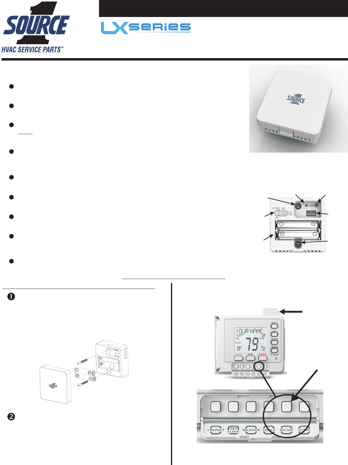
WIRELESS TEMP SENSOR
The S1-LXRFTS requires 2 AAA batteries.
Front Cover Removed
Link Button
DIP
Mounting
Mounting
Bottom
Top
Screw
Screw
Batteries
DIP Switch
Legend
Link LED
+
+
Setup & Installation
The wireless sensor must be linked to a thermostat with an
RF Module installed for proper communication and operation.
RF Module
Installation
Using the supplied screws, attach the rear housing
the mounting surface. For outdoor applications it is
recommended to install the sensor on a surface that is
not in direct sunlight. The components of the sensor
have been precoated at the factory to give limited
protection against moisture.
to
Install 2) AAA batteries as illustrated above.
Battery type recommendation:
Temperature range: 32-120 Fahrenheit, Alkaline.
Temperature range: 0-130 Fahrenheit, Lithium.
+
+
IMPORTANT: DO NOT MOUNT SENSOR IN DIRECT SUNLIGHT
S1-LXRFTS
WIRELESS TEMP SENSOR
S1-LXRFM
Switches
(ACCSRY)
Button
Accessory
To average with a thermostat’s internal sensor.
To average with a thermostat’s internal sensor.
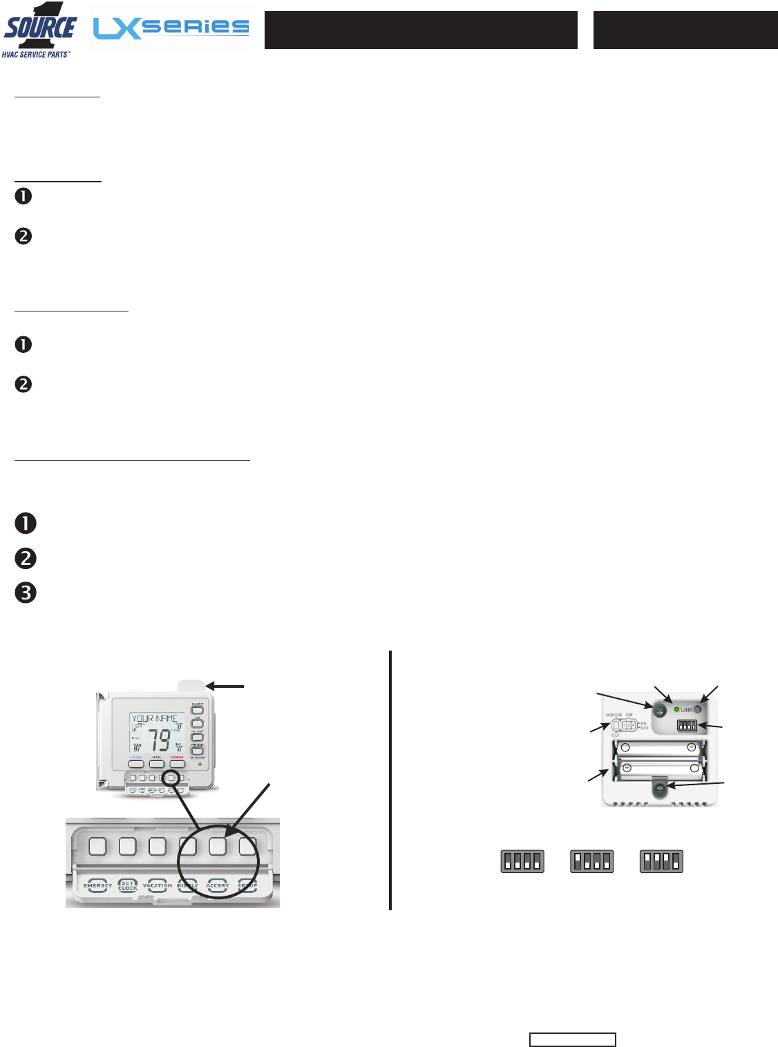
Link Button
DIP Switches
Mounting
Mounting
Bottom
Top
Screw
Screw
Batteries
DIP Switch
Legend
Link LED
+
+
FCC ID MUH-RFTS
Patent Pending
Press the LINK button on the sensor up to or until the indicator light flashes he light will flash for up to
5 minutes or until a link is established.
5 seconds, slowly. T
Press the ACCSRY button on the thermostat to enter the accessory setup screen. Next, press COOLER to enter the wireless
linking or unlinking mode, then press MODE to initiate linking. The thermostat display will confirm if the sensor was
successfully linked.
Linking
Clear Link Database
Continue to press the LINK button for up to 5 seconds after the batteries are reinstalled. When the led
illuminates continuously, this signals that the link database is reset.
Remove the AAA batteries from the Sensor.
Replace the batteries while pressing the LINK button on the wireless sensor.
The link database is an internal listing of all devices that have been successfully paired to the sensor. If it becomes necessary to
clear and reset the link database in the sensor for any reason (such as relocating the sensor to a new location with new devices
or replacing a thermostat with a new RF Module) follow these steps to clear its memory of linked devices:
Unlinking
Press the Link button on the sensor for up to 5 the indicator light flashes slowly.
same Link button on the sensor for another 5 seconds. When the led flashes rapidly, release the Link button.
seconds, or until Release, then press the
Press the ACCSRY button on the thermostat to enter the accessory setup screen. Next, press COOLER to enter the wireless
linking or unlinking mode, then press MODE to initiate unlinking. The thermostat display will confirm if the sensor was
successfully unlinked.
If it becomes necessary to unlink the sensor from the thermostat, follow the steps below.
Examples:
Set the switches on the Wireless Temp Sensor
All switches in the
OFF position = 0.
ADD all switches
in the ON position
to arrive at the
proper setting.
OFF
ON
1 2 4
OFF
ON
1 2 4
OUT
INDOOR
A B C
Outdoor Indoor
ID# = 0
Indoor
ID# = 3 (1+2=3)
OFF
ON
1 2 4
(ID# not used)
The wireless sensor must be linked to a thermostat with an
RF Module installed for proper communication and operation.
S1-LXRFTS
WIRELESS TEMP SENSOR
RF Module
S1-LXRFM
(ACCSRY)
Button
Accessory
To startup the Wireless Temp Sensor, install the batteries as shown on the reverse page. Upon startup, the LED will flash once
indicating the the sensor has been started or reset. After a pause, any additional flashes will indicate how many thermostats the
sensor is currently linked to. If there are no additional LED flashes, the sensor is not linked to any thermostat.
Startup
Note: This equipment has been tested and found to comply with the limits for a Class B digital device, pursuant to part 15 of the FCC Rules. These limits are designed to provide reasonable
protection against harmful interference in a residential installation. This equipment generates, uses and can radiate radio frequency energy and, if not installed and used in accordance with the
instructions, may cause harmful interference to radio communications. However, there is no guarantee that interference will not occur in a particular installation. If this equipment does cause
harmful interference to radio or television reception, which can be determined by turning the equipment off and on, the user is encouraged to try to correct the interference by one or more of the
following measures: 1. Reorient or relocate the receiving antenna. 2. Increase the separation between the equipment and the receiver. 3. Connect the equipment into an outlet on a circuit
different from that to which the receiver is connected. 4. Consult the dealer or an experienced radio/TV technician for help.
This device complies with Part 15 of the FCC Rules. Operation is subject to the following two conditions: (1) this device may not cause
harmful interference, and (2) this device must accept any interference received, including interference that may cause undesired operation.
P/N 88-812 Rev. 3
Operation with non-approved equipment is likely to result in interference to radio and TV reception. The user is cautioned that changes and modifications made to the equipment without the
approval of the manufacturer could void the user’s authority to operate this equipment.