Venstar SKYPORT3 Thermostat with Wi-Fi Module User Manual
Venstar Inc Thermostat with Wi-Fi Module
Venstar >
User Manual
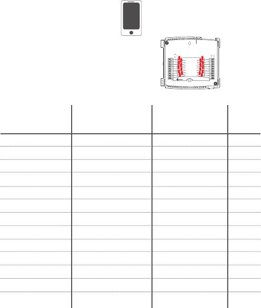
Optional accessories
available, including Wi-Fi
Simply connected.
s
W
i-F
i
cted
.
.
VOYAGER
&
HEAT
COOL
HEAT
PUMP
DIGITAL THERMOSTAT
QUICK START &
SETUP GUIDE
Anytime. Anywhere.*
1
Thank You
Congratulations and thank you for purchasing
your new Venstar VOYAGER® thermostat. This
guide is intended to help you install and setup
the basic features of the VOYAGER® Thermostat.
For a full owners manual and installation guide,
visit venstar.com.
2
Compatibility
Venstar VOYAGER® Thermostat is designed to work with 24V systems
requiring both the R & C wires. This includes gas, electric, oil, forced
air, variable speed, heat pump and radiant heat. It can control:
•Heating:one,twoandthreestages(W1,W2,W3)
•Cooling:oneandtwostages(Y1,Y2)
•Heatpump:withauxiliaryandemergencyheat(Y,W1,O/B)
•Fan(G)
•Power(C,R)
•Humidifierordehumidifier(HUM,DEHUM)
•Dualfuelsystems(heatpumpwithfurnace)
•Whole-homehumidifiersanddehumidifiers
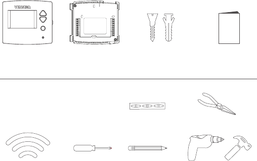
WiFi Network
& Password
Screw Driver Pencil
Leve
lP
liers
Hammer or Drill
(3/16" or 7/ 32" drill bits)
Thermostat Thermostat
Base
Drywall Anchors
and Screws
This Quick Start
Manual
Contents
Necessary Tools
3
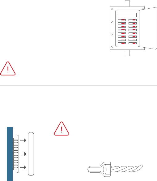
Step 1 - PowerOCurrentSystem
1) Gotoyourhome’scircuitbreakerpanel
and switch the furnace and air conditioner
breakerso.
2) Toconfirmpoweriso,adjustthe
temperature on your current thermostat.
If the system does not respond
accordingly, power has probably been
successfullyshuto.
WARNING: Failure to follow this step can result in personal
injuryand/ordeathfromshockandelectrocution.
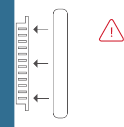
Step 2 - Remove Faceplate
Removethefaceplateofcurrentsystem.Mostfaceplatessnap-oor
feature small screws that will need to be removed.
Side View
Wall Thermostat
WARNING: If you see large thick
electrical wires, wire nuts, or if your
systemislabeled120Vor240VDO
NOTPROCEED.THISTHERMOSTAT
ISNOTCOMPATIBLEWITHTHESE
SYSTEMS
WARNING: Failure to follow this step
canresultinpersonalinjuryand/or
death from shock and electrocution.
4
Step 3 - Beforeyougoanyfurther
Determine what your existing wiring and equipment situation is
before you disconnect any wires. If you are unsure of what type of
system you have, you may need to seek professional support.
A. If you have a Heating only system without Air Conditioning, the
VenstarVOYAGERthermostatwillrequire3wires.These3wires
are:R(24Vac),C(24Vac)andW(Heat).MostHeatingonlysystems
useverysimplethermostatsthatonlyrequire2wirestheR(24Vac)
andW(Heat).TheVOYAGERthermostatrequires3wirestothe
thermostat.InthiscaseanAdd-A-Wireaccessorywillnotwork
anditwillbenecessarytoinstallanotherwirefortheC(24Vac)
connection.
B. Ifyouhaveasingle stage fossil fuel heater with air conditioning,
the Venstar VOYAGER will require 5 wires for independent fan
control.TheyareR(24Vac),C(24Vac),W(Heat),Y(Cooling),andG
(Fan).Youmayconnectonly4 wires, as instructed below, to the
VOYAGER but will give up independent fan control. The fan will
stilloperatewithaHeatingorCoolingdemand.
• If there are only 4 wires present that are connected to the existing
thermostat, there are at least 3 options available to connect the
Venstar VOYAGER thermostat, they are:
1. Usethe4wiresasinstructedbelowandnotethatthefanwill
onlyoperatewithaHeatingorCoolingdemand.
2. PullnewthermostatwirefromtheHVACequipmenttothe
thermostat so that there are at least 5 wires available.
3. PurchaseandinstallaVenstarAdd-A-Wireaccessory
(ACC-0410).
5
C. If you have a multi stage HVAC system comprised of a fossil fuel
heater with air conditioning the Venstar VOYAGER will require the
5wiresmentionedabove(R,C,W,Y,andG)plusanadditionalwire
foreachadditionalstageofHeatingorCooling.Youmayreduce
the 5 wire requirement to 4 if you give up independent fan control,
orusetheoptionalaccessory;Add-A-Wire.
D. Ifyouhaveaheat pump without aux heat the Venstar VOYAGER
willrequire5wires:R(24Vac),C(24Vac),W1/O/B(reversingvalve),Y
(1ststagecompressor),andG(fan).Ifthereareonly4wirespresent
thatareconnectedtotheexistingthermostat,thereareatleast
3optionsavailabletoconnecttheVenstarVOYAGERthermostat,
they are:
1. Usethe4wiresasinstructedbelowandnotethatthefanwill
onlyoperatewithaHeatingorCoolingdemand.
2. PullnewthermostatwirefromtheHVACequipmenttothe
thermostat so that there are at least 5 wires available.
3. PurchaseandinstallaVenstarAdd-A-Wireaccessory(ACC-0410).
E. If you have a heat pump with aux heat the Venstar VOYAGER will
require6wires:R(24Vac),C(24Vac),W1/O/B(reversingvalve),Y(1st
stagecompressor),W2(AuxHeat)andG(fan).Ifthereareonly5
wirespresentthatareconnectedtotheexistingthermostat,there
areatleast3optionsavailabletoconnecttheVenstarVOYAGER
thermostat, they are:
1. Usethe5wiresasinstructedbelowandnotethatthefanwill
onlyoperatewithaHeatingorCoolingdemand.
2. PullnewthermostatwirefromtheHVACequipmenttothe
thermostat so that there are at least 6 wires available.
3. PurchaseandinstallaVenstarAdd-A-Wireaccessory(ACC-0410).
6
MAKING 4 WIRES WORK when 5 are required
(without the optional Add-A-Wire accessory)
• If you have an all-electric heat system with air conditioning, this
method is not an option. You must either pull new wire or use the
optional Add-A-Wire accessory (ACC-0410).
• If you have a single stage fossil fuel heater with air conditioning,
and you would like install the Venstar VOYAGER using only 4 wires,
follow the directions below. You will need a screwdriver along with a
3” or 4” long piece of thermostat wire to use as a jumper.
1. Makesurethepowerisoasstep1onpage4instructsyou.
2. Followstep4onpage9“LabelandDisconnectWires”atthe
thermostat.Pleasenotethecolorandthecorrespondingwire
designatorwitheachcolor.AnexampleistheRwireisredandthe
Wwireiswhiteandsoon.Youwillneedthisforthenextstepat
theHVACequipment.
3. Attheequipmentendofthethermostatwires,locatethe
terminals that the wires are attached to.
A. Removethe“Gwire”fromtheterminalmarkedG.
B. Placethe“Gwire”onterminalC.
C. PlaceoneendofthejumperonterminalG.
D. PlacetheotherendofthejumperonterminalY.
Pleasenotethattherewillbemorethan1wireonterminalY.
4. Connect the wires to the terminals on the VOYAGER backplate
takingcaretomakesurethateachwirefromtheHVACequipment
is connected to the same terminal designation on the VOYAGER
backplate.Forexample:the“Cwire”fromtheHVACequipment
shouldbeconnectedtothe“C”terminalofthethermostat.The
“R”wireontheequipmentterminalshouldbeconnectedtothe
“R”terminalontheVOYAGERbackplate,andsoon.
7
MAKING 5 WIRES WORK when 6 are required
(without the optional Add-A-Wire accessory)
• If you have an all-electric heat system with air conditioning, this
method is not an option. You must either pull new wire or use the
optional Add-A-Wire accessory (ACC-0410).
• If you have a multi stage system that requires 6 wires, and you
would like install the Venstar VOYAGER using only 5 wires, follow the
directions below. You will need a screwdriver along with a 3” or
4” long piece of thermostat wire to use as a jumper.
1. Makesurethepowerisoasstep1onpage6instructsyou.
2. Followstep4onpage9“LabelandDisconnectWires”atthe
thermostat.Pleasenotethecolorandthecorrespondingwire
designatorwitheachcolor.AnexampleistheRwireisredandthe
Wwireiswhiteandsoon.Youwillneedthisforthenextstepat
theHVACequipment.
3. Attheequipmentendofthethermostatwires,locatethe
terminals that the wires are attached to.
A. Removethe“Gwire”fromtheterminalmarkedG.
B. Placethe“Gwire”onterminalC.
C. PlaceoneendofthejumperonterminalG.
D. PlacetheotherendofthejumperonterminalY.
Pleasenotethattherewillbemorethan1wireonterminalY.
E. Connect the wires to the terminals on the VOYAGER backplate
takingcaretomakesurethateachwirefromtheHVAC
equipment is connected to the same terminal on the VOYAGER
backplate.Forexample:the“Cwire”fromtheHVACequipment
isconnectedtothe“C”terminalofthethermostatandsoon.
8
Step 4 - Label&DisconnectWires
1) Onebyone,applyalabel
designated to each wire
you disconnect from
your current thermostat.
TIP:Beforedisconnectinganywires,
take a photo of your current wire
configurationwithyourmobiledevice.
Wirefromthe Installonthe
oldthermostat Function newthermostat Wire
terminal marked connector marked Color
G or F Fan G
Y1,Y Cooling Y1
W1,W Heating W1/0/B
Rh,R,M,Vr,A Power R
C Common C
O/B Rev.Valve W1/O/B*
W2 2ndStageHeat W2
Y2 2ndStageCooling Y2
W3 3rdStageHeat W3
H,Hum Humidity HUM
D,Dehum Dehumidity DEHUM
Ck1 DryContactSwitch DRYCONTACT
CKGND DryContactSwitch DRYCONTACT
*O/BisusedifyoursystemisaHeatPump.
9
Step 5 - RemoveCurrentBackplate
Unscrewthecurrentbackplateand
removeitfromthewall.Becareful
not to let the wires fall into the wall.
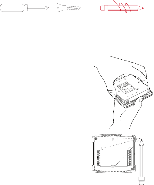
Step 6 - MountNewBase
1) Gentlyseparatethedisplayfromthebasebypullingfirst
from one side, then the other until the two pieces unsnap.
A small screwdriver may be used, very carefully, to start
seperating the two pieces.
TIP: If needed, wrap the wires
around a pencil or pen to keep
them from falling inside the wall.
2) Positionthebaseagainstyour
wall, and determine if wall
anchors from current thermostat
align with screw locations of
new base.
3) Ifbasedoesnotalignwith
existinganchorholes,marknew
screw locations with a pencil.
Drywall:Drill3/16"holefor
the anchor
Plaster:Drill7/32”holefor
the anchor
4) Pullwiresthroughopeningin
base and secure to the wall
using provided screws.
TIP:Usealeveltoensure
thermostat is properly aligned
before marking screw locations.
10
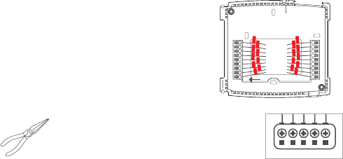
Step 7 - ConnectWires
1) Matchyourpreviouswireconfiguration
to the new base. One by one, connect
each wire by inserting the metal end into
the corresponding slot and tightening
the screw.
TIP: Useplierstostraightenwirebefore
insertingintonewbase.Besuretocutany
excesswiresothattheinsulationextendsto
theterminalblock.Whenthewireisinstalled
properly to the terminal block, there should
benocopperexposed.
WiFi Network
& Password
Screw Driver Pencil
LevelPliers
Hammer or Drill
(3/16" or 7/ 32" drill bits)
Thermostat Thermostat
Base
Drywall Anchors
and Screws
This Quick Start
Manual
W3/AUX
W2
W1/O/B
Y2
Y1
SENSOR
11
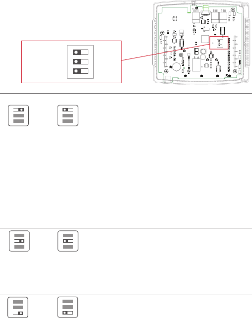
Step 8 - CheckDipSwitch
1) Ensurewhichswitchiscorrectfor
yoursystem.Dipswitchesarelocated
on the back of the thermostat
GAS/EL HP
OR
GAS/EL HP
ON
1 2 3
ON
1 2 3
OR
OBBO
ON
1 2 3
ON
1 2 3
GAS ELEC
OR
GAS ELEC
ON
1 2 3
ON
1 2 3
1
GAS
O
GAS/EL
ELEC
B
HP
ON
23
1
GAS
O
GAS/EL
ELEC
B
HP
ON
23
1.WhenGAS/EL or HP is set for GAS/EL:
Thisswitch(GASorELEC)controlshowthe
thermostatwillcontroltheFan(G)terminalin
heatingmode.WhenGAS is chosen, the thermostat
will notenergizetheFan(G)terminalinheating.
WhenELEC is chosen the thermostat will energize
the fan in heating.
2.WhenGAS/EL or HP is set for HP:
Thisswitch(GASorELEC)definestheAuxHeattype.
WhenGASischosen,theauxiliaryheatwillnotbe
allowedtorunduringheatpumpoperation.When
usingaDualFuelsystem,setthisswitchforGAS.
WhenELECischosen,uptotwostagesofauxiliary
strip heat will be allowed to run.
For Heat Pump Only
WhentheGAS/ELorHPdipswitchisconfiguredfor
HP,thisdipswitch(OorB)mustbesettocontrol
the appropriate reversing valve. If O is chosen,
theW1/O/Bterminalwillenergizeincooling.If
Bischosen,theW1/O/Bterminalwillenergizein
heating.
Thisdipswitchconfiguresthethermostattocontrol
aconventionalgas/electricsystemoraheatpump.
If your system is anything other than a heat pump,
leave this switch set for GAS/EL.
12
Step 9 - Attach Thermostat
1) Alignthepinsonthethermostatcircuitboardwiththecorresponding
holes below the wiring connectors and push the top and the bottom
of the plastic housing enclosing the display until it clicks into place,
top and bottom.
Step 10 - SwitchPower/CircuitBreakersBackOn
Turn your furnace and air conditioner breakers back on at your breaker
panel.
Side View
Displayshouldclickinto
place easily. If you encounter
resistancedonotapplyexcess
force–taketheplateo,
check that the pins are straight
and ensure there are no wires
in the way and retry.
13
Step 11 - SetUpWi-FiConnection
(Using the optional WiFi module)
Overview
Atminimum,thefirst3tasksbelowmustbecompletedtoaccessyour
thermostatremotelyfromabrowser.The4thstepisoptional(highly
recommended)andonlyisneededtoaccessyourthermostat(s)from
a mobile device.
These steps are:
1. SuccessfulconnectiontoalocalWi-FiAccessPointwithinternet
access.
2. ConfirmreceiptofaSkyportgeneratedverificationemail(thisonly
occursonceduringtheSkyportaccountsetup).
3. A6-digitcodeobtainedfromthethermostatissuccessfully
enteredintoaSkyportaccount.
4. SuccessfullydownloadandinstalltheVenstarSkyportapponyour
mobiledevice(s).
Your thermostat operates on the 2.4 Ghz, Wi-Fi b/g/n band.
14
1 2
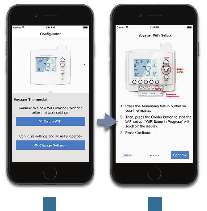
Quick Start - Connect to Wi-Fi
TheVoyagerthermostatsarejoinedtoaWi-Finetworkwiththe
helpoftheVenstarConfiguratorApp.Thisappmaybedownloaded
fromyourmobiledevice’sappstore.OncetheVoyagerthermostatis
installedwiththeoptionalWi-FiModule,theConfiguratorAppwill
facilitate connection to the access point in 5 steps as outlined below.
Press the “Setup
Wi-Fi” button.
Press the “Accessory
Setup Wi-Fi” button on
the thermostat.
Then press the “Cooler”
button to start the setup.
15
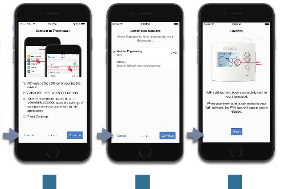
3 4 5
Go to the settings
of the mobile
device. Select
Wi-Fi, then select
the Voyager
thermostat.
Return to the
Configurator App.
Select the access
point to join.
The Wi-Fi icon
appears on the
display when
successfully
connected.
Quick Start - Connect to Wi-Fi (continued)

16
Quick Start - Connect to Skyport
IfthethermostatisconnectedtothelocalWi-FiAccessPoint,butnot
yetjoinedtoaSkyportaccount,youmayjointhethermostattoan
account by doing the following:
1. Openyourbrowserto:http://venstar.skyportcloud.com
2. Select“Createaccountnow”
3. Followonscreeninstructionstocreateanaccountandadda
thermostattotheSkyportaccount.
Create Account Now
4

17
Troubleshooting
Usethefollowingtroubleshootingguidetodiagnosecommon
problems. If you are still having problems or are unsure please
visit www.venstar.com/thermostatsore-mailcustomerserviceat
thermostatsupport@venstar.com
Problem
The air conditioning does
not attempt to turn on.
The display is blank.
The heating does not
attempt to turn on.
Whenusingaresidential
heat pump the heat comes
on instead of the air
conditioning.
Whencallingforair
conditioning both the heat
and cool come on.
Possible Cause
The compressor timer
lockout may prevent the air
conditioner from turning on
for a period of time.
The cooling setpoint is set
too high.
You may have selected Free
Cooling in settings.
Lackofproperpower.
The heating setpoint is set
too low.
The thermostat reversing
valve dip switch is set
incorrectly.
The thermostat equipment
dipswitchisconfiguredfor
“HP”andtheHVACunitisa
gas/electric.
Solution
Adjustthe
CompressorMin.OTIme
to“None”.
Lowerthecoolingsetpoint
or lower the cooling
setpoint limit.
Ifyoudon’thaveadamper,
and special duct work
installed,turnothis
feature in settings.
Makesurethepower
is on to the furnace
and that you have a 24 vac
between R&C.
Raise the
heating setpoint or raise
the heating setpoint limit.
Setthereversingvalvedip
switch to the opposite
position.
Settheequipmentdip
switchfor“gas”.
18
One-Year Warranty - This Product is warranted to be free from defects in material and
workmanship. If it appears within one year from the date of original installation, whether
or not actual use begins on that date, that the product does not meet this warranty, a new
or remanufactured part, at the manufacturer’s sole option to replace any defective part, will
be provided without charge for the part itself provided the defective part is returned to the
distributor through a qualified servicing dealer.
THIS WARRANTY DOES NOT INCLUDE LABOR OR OTHER COSTS incurred for diagnosing,
repairing, removing, installing, shipping, servicing or handling of either defective parts or
replacement parts. Such costs may be covered by a separate warranty provided by the installer.
THIS WARRANTY APPLIES ONLY TO PRODUCTS IN THEIR ORIGINAL INSTALLATION LOCATION
AND BECOMES VOID UPON REINSTALLATION.
LIMITATIONS OF WARRANTIES – ALL IMPLIED WARRANTIES (INCLUDING IMPLIED WARRANTIES
OF FITNESS FOR A PARTICULAR PURPOSE AND MERCHANTABILITY) ARE HEREBY LIMITED IN
DURATION TO THE PERIOD FOR WHICH THE LIMITED WARRANTY IS GIVEN. SOME STATES DO
NOT ALLOW LIMITATIONS ON HOW LONG AN IMPLIED WARRANTY LASTS, SO THE ABOVE MAY
NOT APPLY TO YOU. THE EXPRESSED WARRANTIES MADE IN THIS WARRANTY ARE EXCLUSIVE
AND MAY NOT BE ALTERED, ENLARGED, OR CHANGED BY ANY DISTRIBUTOR, DEALER, OR
OTHER PERSON WHATSOEVER.
ALL WORK UNDER THE TERMS OF THIS WARRANTY SHALL BE PERFORMED DURING NORMAL
WORKING HOURS. ALL REPLACEMENT PARTS, WHETHER NEW OR REMANUFACTURED,
ASSUME AS THEIR WARRANTY PERIOD ONLY THE REMAINING TIME PERIOD OF THIS
WARRANTY.
THE MANUFACTURER WILL NOT BE RESPONSIBLE FOR:
1. Normal maintenance as outlined in the installation and servicing instructions or owner’s
manual, including filter cleaning and/or replacement and lubrication.
2. Damage or repairs required as a consequence of faulty installation, misapplication, abuse,
improper servicing, unauthorized alteration or improper operation.
3. Failure to start due to voltage conditions, blown fuses, open circuit breakers or other damages
due to the inadequacy or interruption of electrical service.
4. Damage as a result of floods, winds, fires, lightning, accidents, corrosive environments or
other conditions beyond the control of the Manufacturer.
5. Parts not supplied or designated by the Manufacturer, or damages resulting from their use.
6. Manufacturer products installed outside the continental U.S.A., Alaska, Hawaii, and Canada.
7. Electricity or fuel costs or increases in electricity or fuel costs for any reason whatsoever
including additional or unusual use of supplemental electric heat.
8. ANY SPECIAL INDIRECT OR CONSEQUENTIAL PROPERTY OR COMMERCIAL DAMAGE
OF ANY NATURE WHATSOEVER. Some states do not allow the exclusion of incidental or
consequential damages, so the above may not apply to you.
This warranty gives you specific legal rights and you may also have other rights which may vary
from state to state.
Warranty
19
FCC Compliance Statement
This equipment has been tested and found to comply with the limits for an
intentional radiator, pursuant to Part 15, subpart C of the FCC rules. These limits
are designed to provide reasonable protection against harmful interference
in a residential installation. This equipment generates, uses and can radiate
radio frequency energy and, if not installed and used in accordance with
the instructions, may cause harmful interference in radio communications.
However, there is no guarantee that the interference will not occur in a
particular installation. If this equipment does cause harmful interference
to radio or television reception, which can be determined by turning the
equipment off and on, the user is encouraged to try to correct the interference
by one or more of the following measures:
• Reorient or relocate the receiving antenna.
• Increase the separation between the equipment and receiver.
• Connect the equipment into an outlet on a circuit different from that of the
receiver.
• Consult the dealer or an experienced radio or TV technician for help.
Notice: Only peripherals complying with FCC limits may be attached to this
equipment. Operation with noncompliant peripherals or peripherals not
recommended by Venstar, is likely to result in interference to radio and TV
reception. Changes or modifications to the product, not expressly approved by
Venstar could void the user’s authority to operate the equipment.
FCC - INDOOR Mobile Radio Information:
To comply with FCC/IC RF exposure limits for general population / uncontrolled
exposure, the antenna(s) used for this transmitter must be installed to provide
a separation distance of at least 20 cm from all persons and must not be co-
located or operating in conjunction with any other antenna or transmitter.
This Device complies with Industry Canada License-exempt RSS standard(s).
Operation is subject to the following two conditions: 1) this device may not
cause interference, and 2) this device must accept any interference, including
interference that may cause undesired operation of the device.
Under Industry Canada regulations, this radio transmitter may only operate
using an antenna of a type and maximum (or lesser) gain approved for the
transmitter by Industry Canada. To reduce potential radio interference to other
users, the antenna type and its gain should be so chosen that the equivalent
isotropically radiated power (e.i.r.p.) is not more than that necessary for
successful communication.
(continued)

20
Cet appareil est conforme avec Industrie Canada, exempts de licence standard
RSS(s). Son fonctionnement est soumis aux deux conditions suivantes: 1) ce
dispositif ne doit pas causer d’interférences, et 2) ce dispositif doit accepter
toute interférence, y compris les interférences qui peuvent causer un mauvais
fonctionnement de l’appareil.
En vertu des règlements d’Industrie Canada, cet émetteur de radio ne peut
fonctionner en utilisant une antenne d’un type et maximale (ou moins) Gain
approuvé pour l’émetteur par Industrie Canada. Pour réduire les interférences
radio potentielles aux autres utilisateurs, le type d’antenne et son gain doivent
être choisis afin que la puissance isotrope rayonnée équivalente (PIRE) ne est
pas plus de ce qui est nécessaire pour une communication réussie.
We, Venstar, declare under our sole responsibility that the device to which
this declaration relates: Complies with Part 15 of the FCC Rules. Operation is
subject to the following two conditions: (1) this device may not cause harmful
interference, and (2) this device must accept any interference received,
including interference that may cause undesired operation.
FCC ID: MUH-SKYPORT3
IC: 12547A-SKYPORT3
These numbers can be located on the inside of the thermostat backplate,
in the upper right corner.
MUH-SKYPORT3

Patents Issued & Pending
Printed on recycled paper.
P/N 88-1114 Rev. 1 06/15