Verifone 1619-20XPL Contactless Card Reader Module User Manual Flash II Installation Guide A
VeriFone Inc Contactless Card Reader Module Flash II Installation Guide A
UserManual.wiki
>
Verifone
>
1619 20XPL User Manual
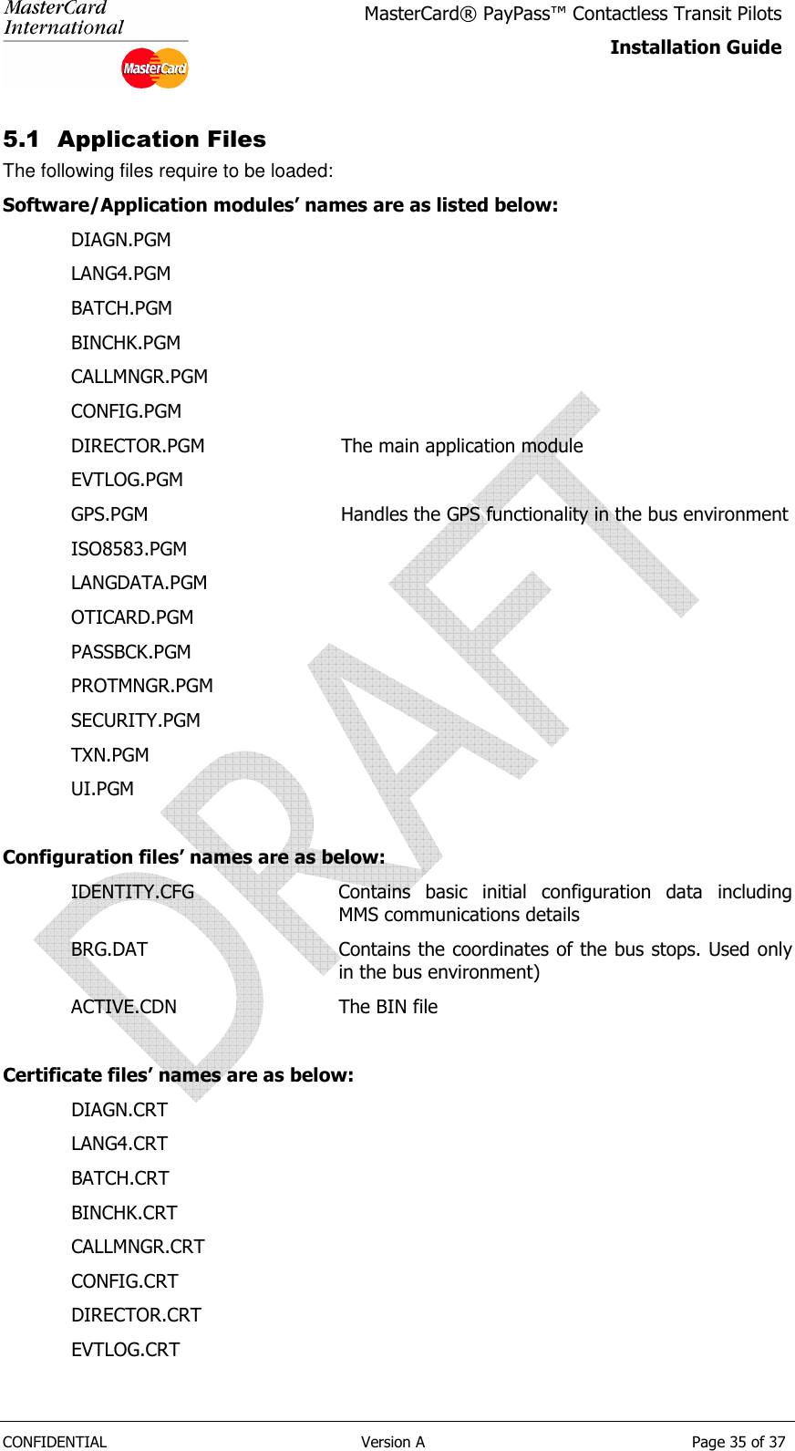
Installation Guide
Navigation menu
Upload a User Manual
Namespaces
Wiki Guide
HTML
PDF
Info
Views
User Manual
Discussion / Help
Navigation
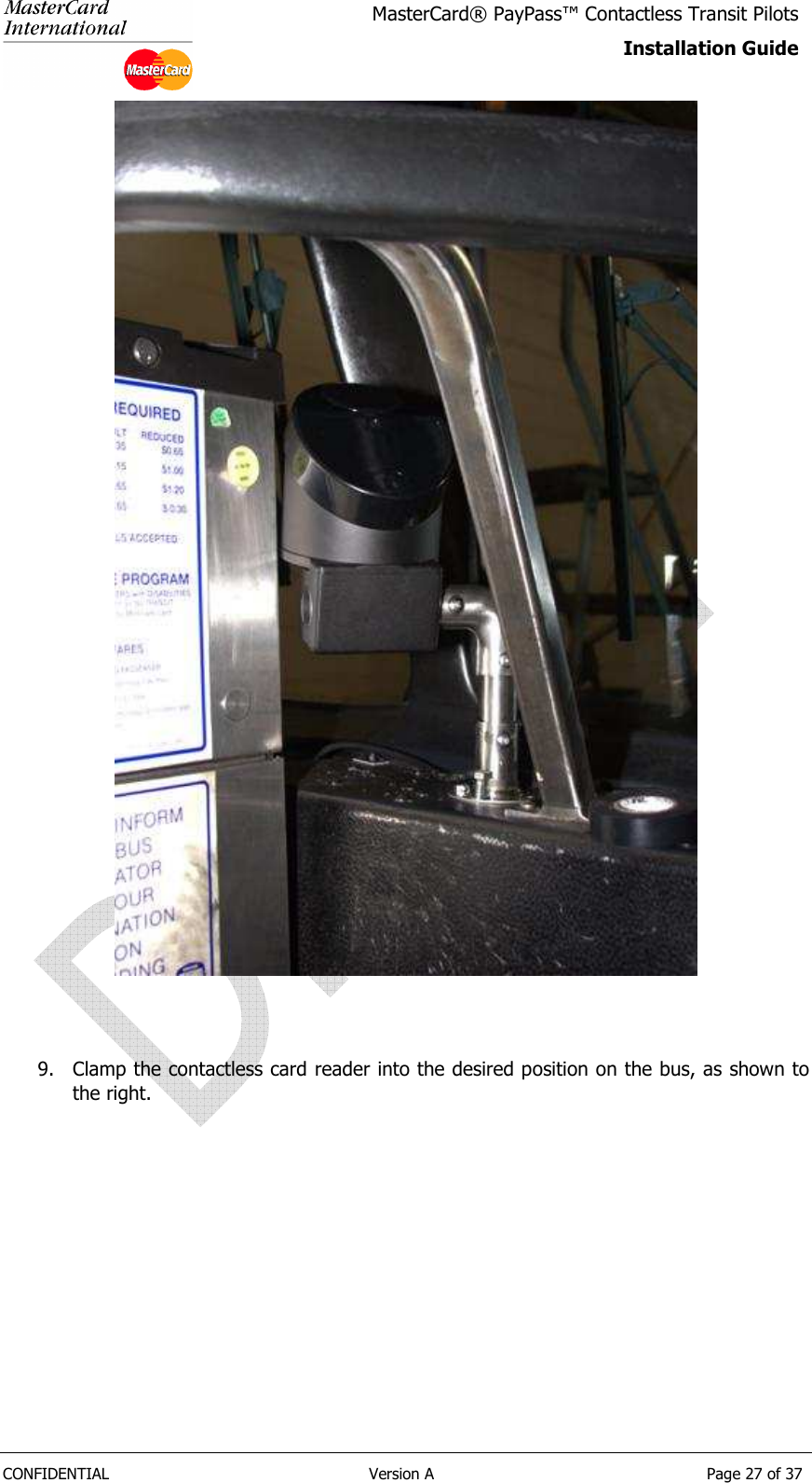
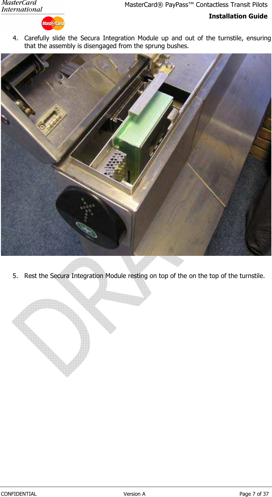
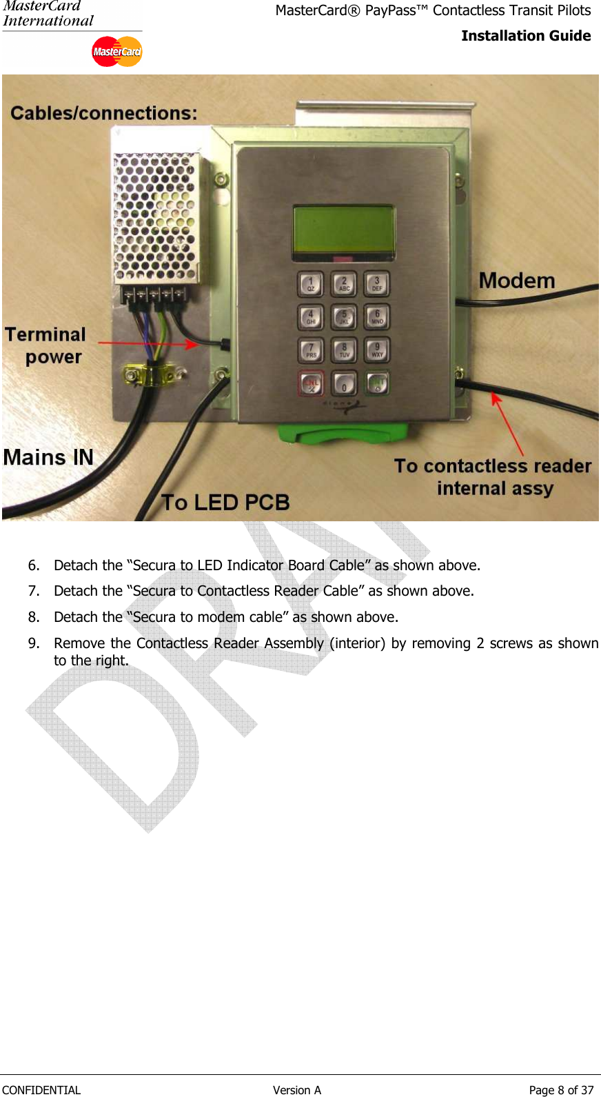
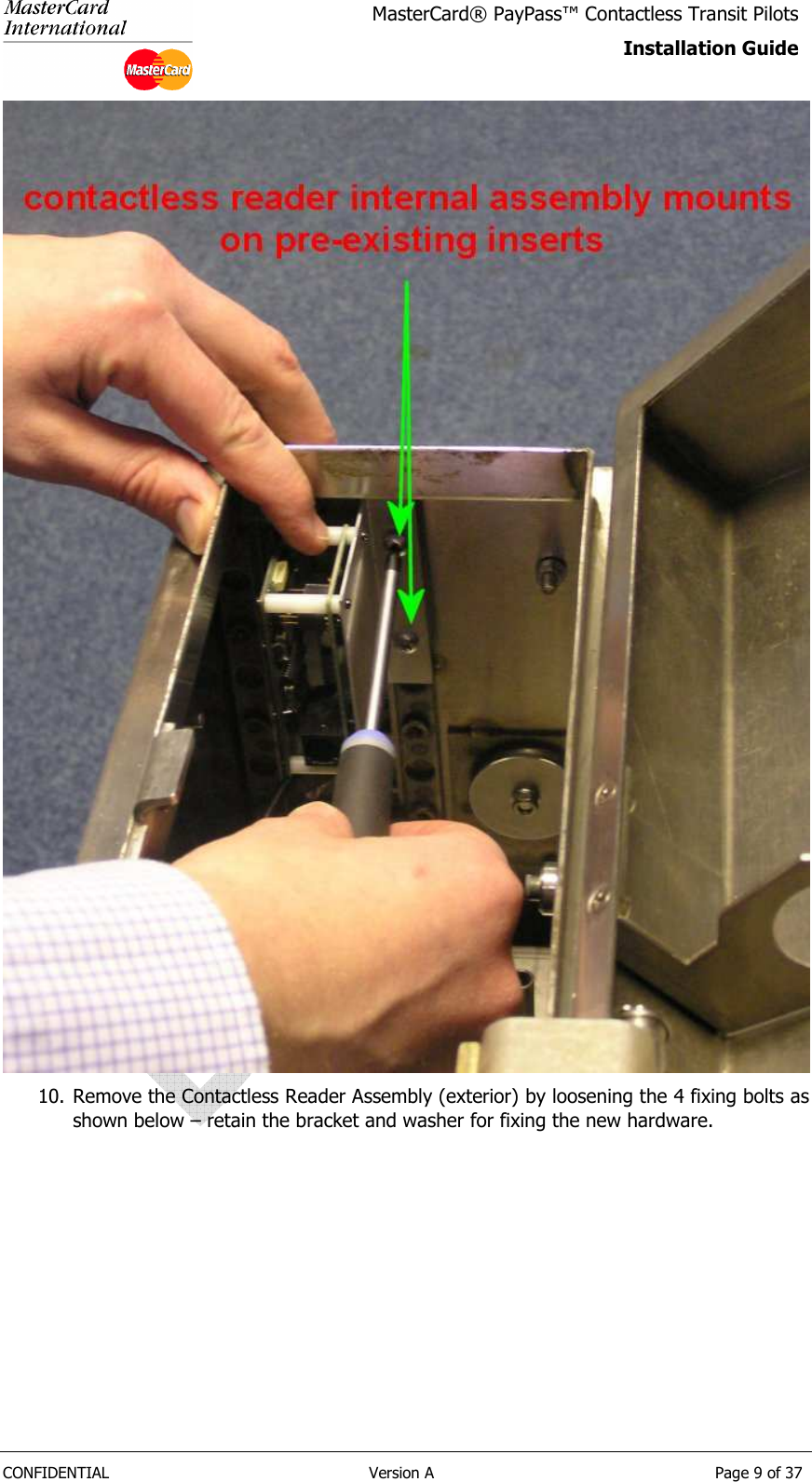
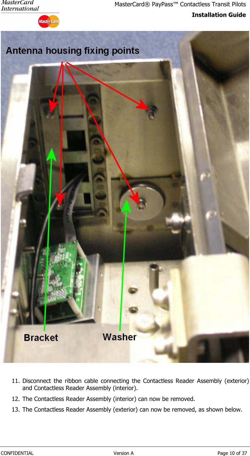
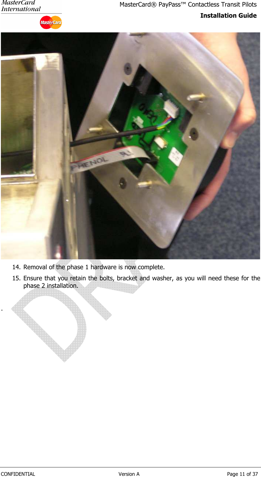
![CONFIDENTIAL Version A Page 6 of 37 MasterCard® PayPass™ Contactless Transit Pilots Installation Guide 2.5 Upgrade Process References annotated [value] in this section are to the assemblies / items defined in section 2.2. 2.5.1 Stage 1 – Remove Existing Phase 1 Hardware The first stage of the upgrade is to remove the existing phase 1 solution. 2. Open the top of the turnstile to reveal the phase 1 installation, as shown. 3. Power down the terminal by unplugging in the 3-Pin plug.](https://usermanual.wiki/Verifone/1619-20XPL/User-Guide-1185996-Page-6.png)
![CONFIDENTIAL Version A Page 12 of 37 MasterCard® PayPass™ Contactless Transit Pilots Installation Guide 2.5.2 Stage 2 – Fixing Phase 2 hardware to the Mounting Plate 1. You will need to retain the Secura mounting plate, as it is required to mount the phase 2 solution. Remove the 4 bolts left and right of the Secura, (see below) taking care to retain the bolts for fixing the phase 2 solution. 2. Attach the adapter plate [3] to the mounting plate. 3. Attach the phase 2 Secura Control Unit [2] to the adapter plate [3]. 4. The Secura is now ready to install in the turnstile.](https://usermanual.wiki/Verifone/1619-20XPL/User-Guide-1185996-Page-12.png)
![CONFIDENTIAL Version A Page 13 of 37 MasterCard® PayPass™ Contactless Transit Pilots Installation Guide 2.5.3 Stage 3 – Installing the Phase 2 hardware 1. Select the Contactless Reader Assembly [1]. Ensure that the OTI Reader cable [4] and the LED Board cable [5] are attached to the card reader assembly. 2. Position so that the attached cable assemblies can be fed through the second lowest square aperture on the front of the turnstile, as shown. Feed the two cable assemblies through the aperture. 3. Secure the contactless card reader assembly to the turnstile using the bracket [retained from phase 1], washer [retained from phase 1] and bolts [retained from phase 1].](https://usermanual.wiki/Verifone/1619-20XPL/User-Guide-1185996-Page-13.png)
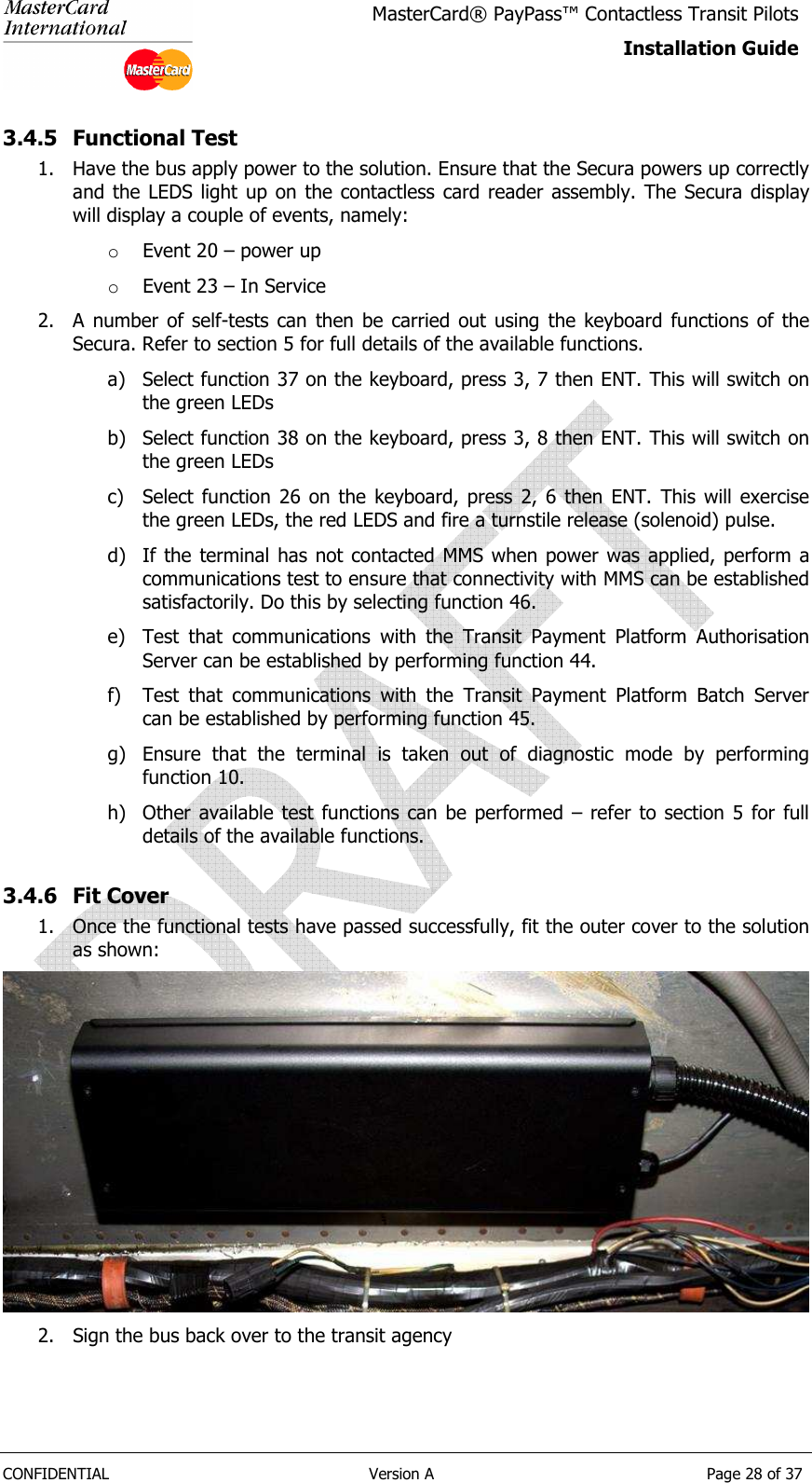
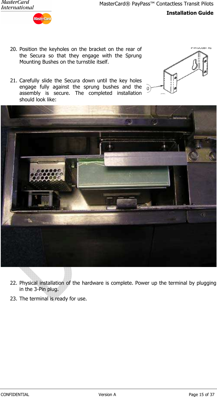
![CONFIDENTIAL Version A Page 14 of 37 MasterCard® PayPass™ Contactless Transit Pilots Installation Guide NOTE PLEASE ENSURE THAT THE POWER CABLE IS NOT PLUGGED INTO THE 3-PIN SOCKET BEFORE THE NEXT STEP. 4. Attach LAN cable [6] to the connection point in the turnstile. 5. Rest the Secura on the top of the turnstile. 6. Attach the Secura Control Unit Assembly [2] to the LED Indicator Board Cable [5] as shown above. 7. Attach the Secura Control Unit Assembly [2] to Secura to Contactless Reader Cable [4] as shown above. 8. Attach the Secura Control Unit Assembly [2] to the LAN cable [6] as shown above. 9. Attach the Secura Control Unit Assembly [2] to Solenoid cable [7] 10. Ensure that all connection points are fully home. 11. With the Secura still resting on the top of the turnstile, plug in the power and ensure that the Secura powers up correctly and the LEDS light up. The Secura display will display a couple of events, namely: o Event 20 – power up o Event 23 – In Service 16. The terminal may attempt to contact MMS at this point, to pick up its configuration. This will take a few moments to complete. 17. A number of self-tests can then be carried out using the key board functions of the Secura. Refer to section 5 for full details of the available functions. a) Select function 37 on the keyboard, press 3, 7 then ENT. This will switch on the green LEDs b) Select function 38 on the keyboard, press 3, 8 then ENT. This will switch on the green LEDs c) Select function 26 on the keyboard, press 2, 6 then ENT. This will exercise the green LEDs, the red LEDS and fire a turnstile release (solenoid) pulse. d) If the terminal has not contacted MMS when power was applied, perform a communications test to ensure that connectivity with MMS can be established satisfactorily. Do this by selecting function 46. e) Test that communications with the Transit Payment Platform Authorisation Server can be established by performing function 44. f) Test that communications with the Transit Payment Platform Batch Server can be established by performing function 45. g) Ensure that the terminal is taken out of diagnostic mode by performing function 10. h) Other available test functions can be performed – refer to section 5 for full details of the available functions. 18. Remove power by unplugging the 3-Pin plug. 19. Position the Secura into the body of the turnstile ensuring that the cables are not trapped or likely to be stretched when positioning the Secura into its bracket.](https://usermanual.wiki/Verifone/1619-20XPL/User-Guide-1185996-Page-14.png)
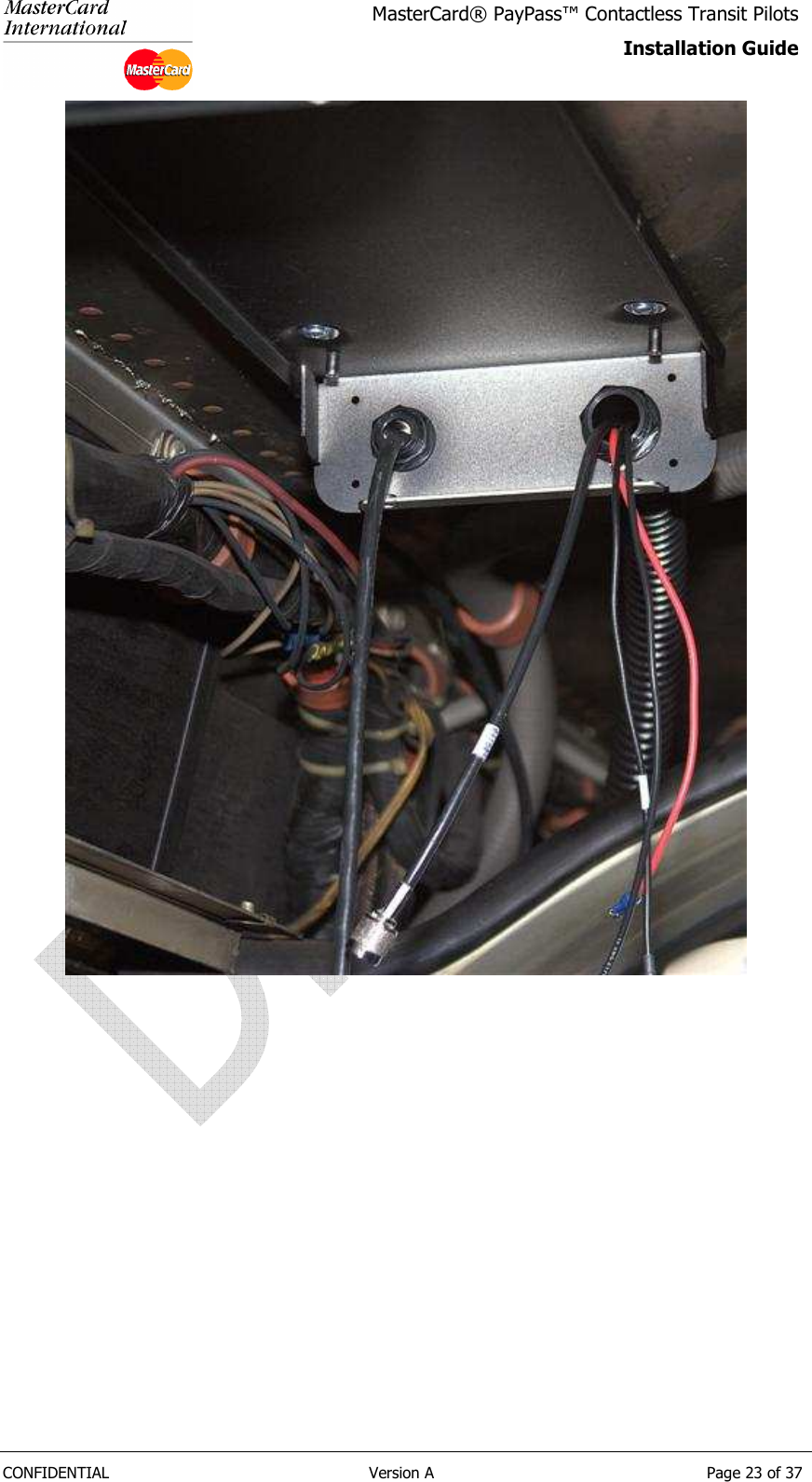
![CONFIDENTIAL Version A Page 22 of 37 MasterCard® PayPass™ Contactless Transit Pilots Installation Guide 3.4.3 Install the Secura Control Unit 1. Attach the support bracket [8] to the agreed position on the bus, as shown: 2. Cut about 15cm (6in) of flexible tubing 3. Feed the antenna cables through the flexible tubing 4. Feed the power cables through the flexible tubing 5. Feed the cables into the support bracket as shown. The 12-way connector cable shall be fed through the left aperture. The antenna cable, power cable and GPS cable shall be fed through the right hand aperture as shown. Note that that antenna cable should be fed through before the other two, as the connector is quite large relative to the aperture.](https://usermanual.wiki/Verifone/1619-20XPL/User-Guide-1185996-Page-22.png)