Verifone M400WIFIBT Multilane Point of Sale Terminal User Manual M400 Installation Guide
VeriFone Inc Multilane Point of Sale Terminal M400 Installation Guide
UserManual.wiki
>
Verifone
>
M400WIFIBT User Manual
>
Manual
Contents
1.
Manual
2.
Manual - Compliance Statement
3.
Manual Statement
4.
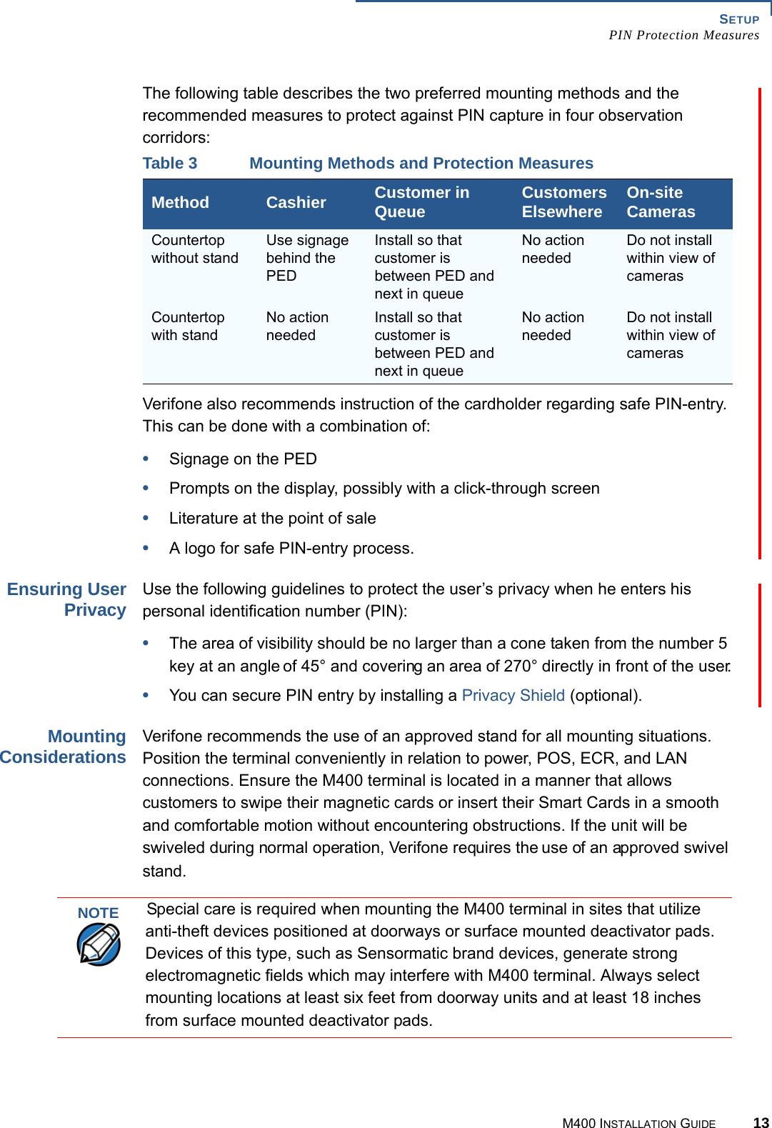
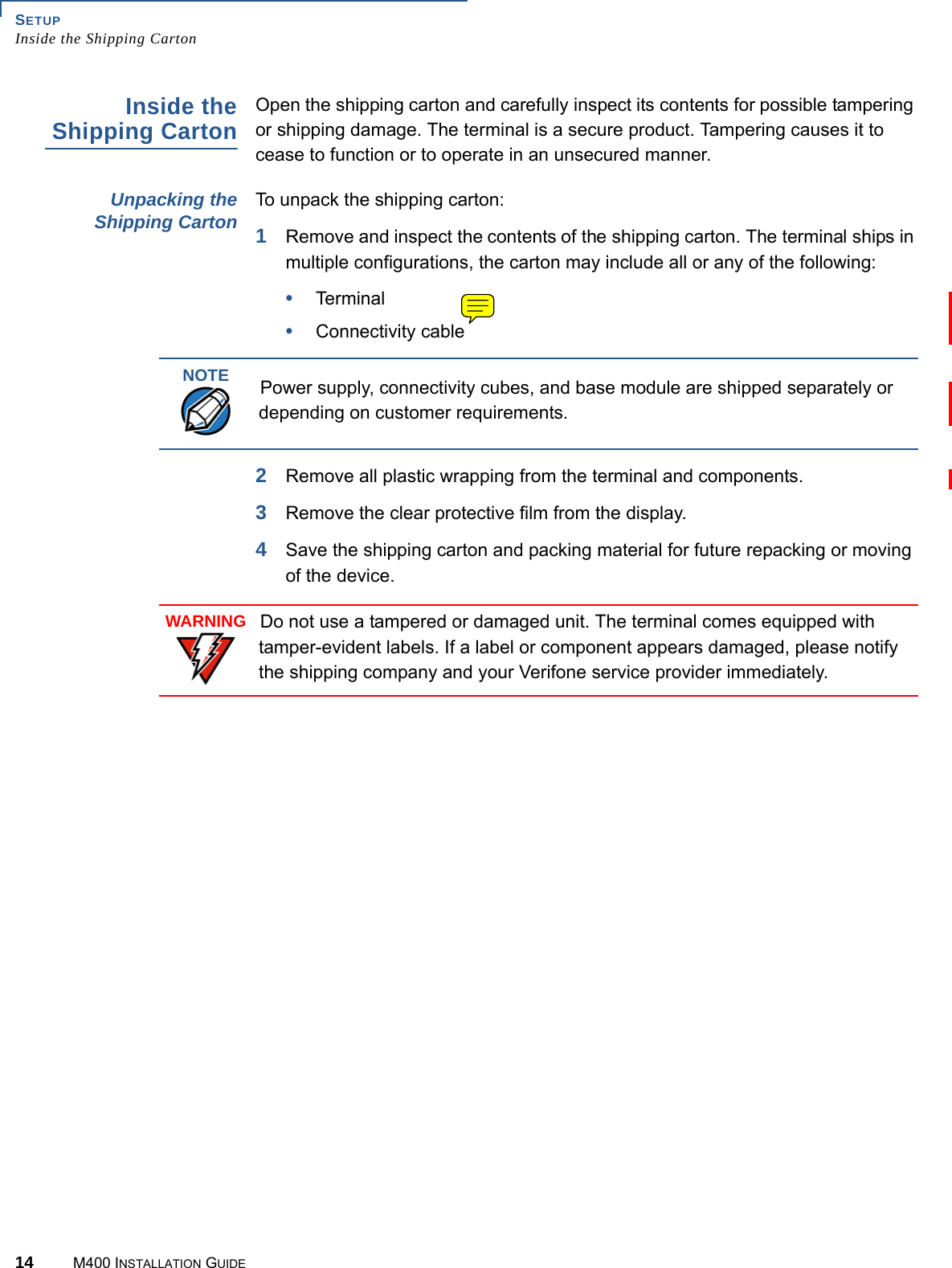
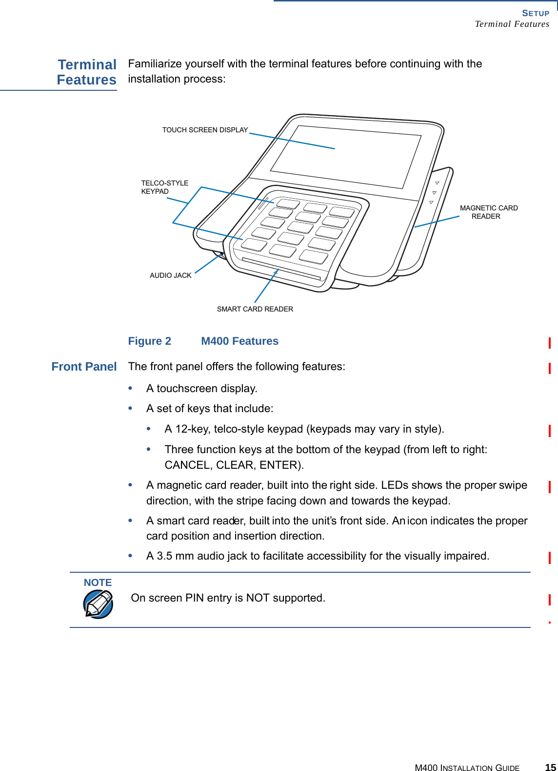
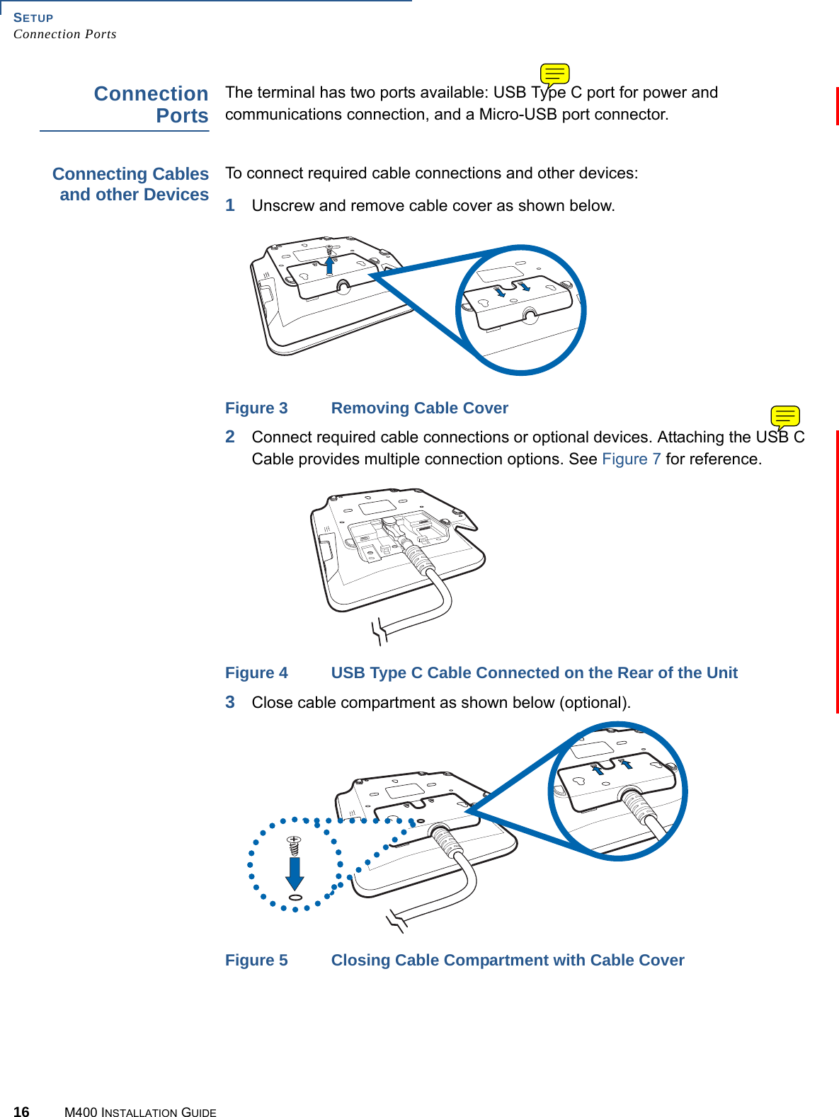
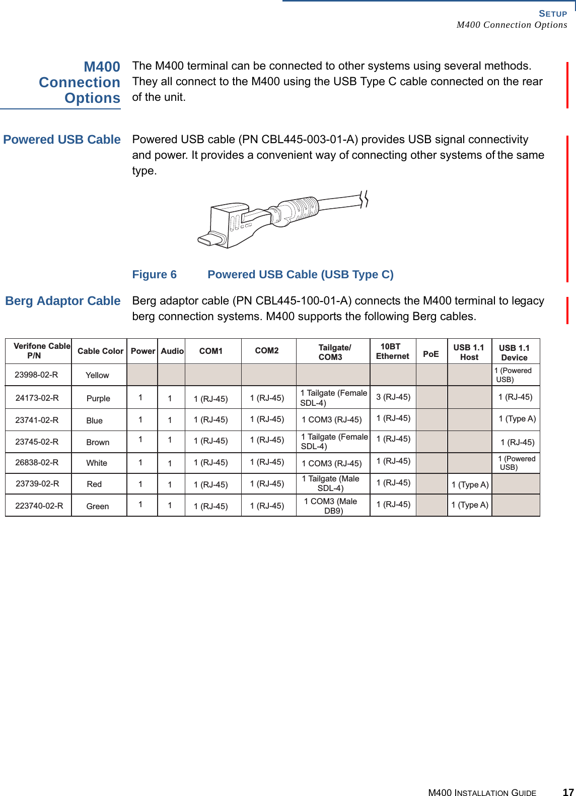
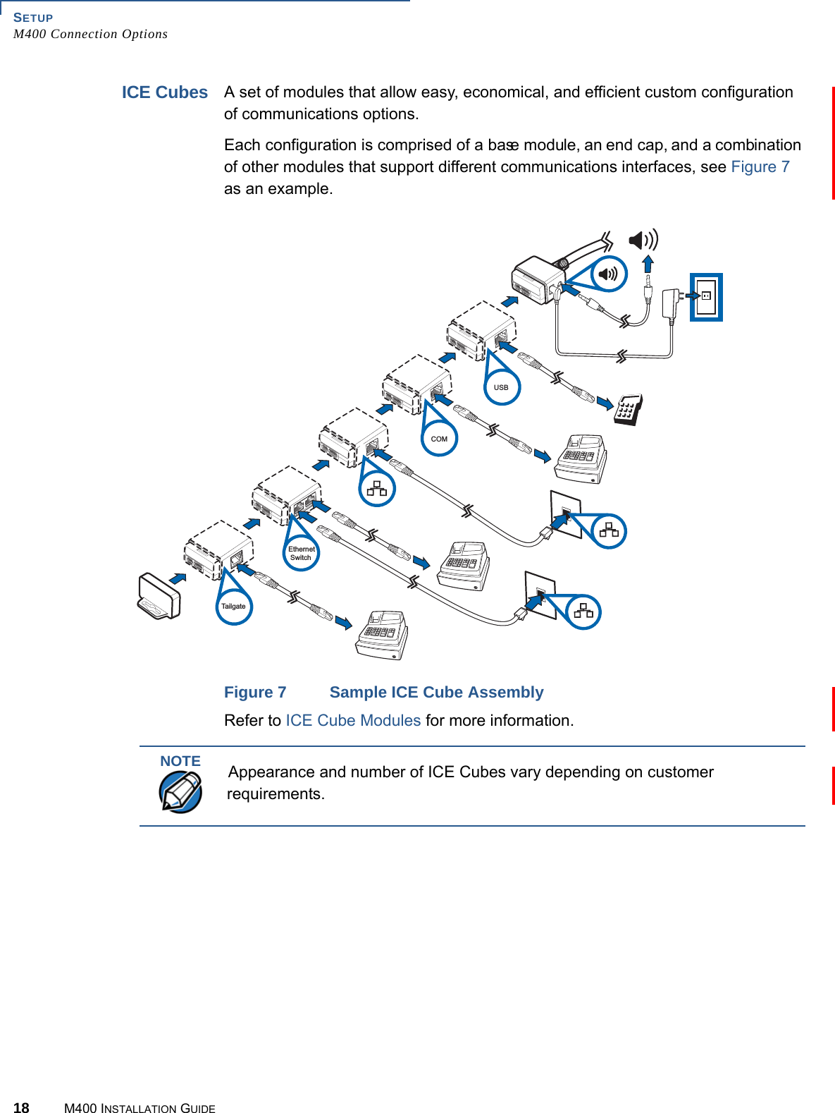
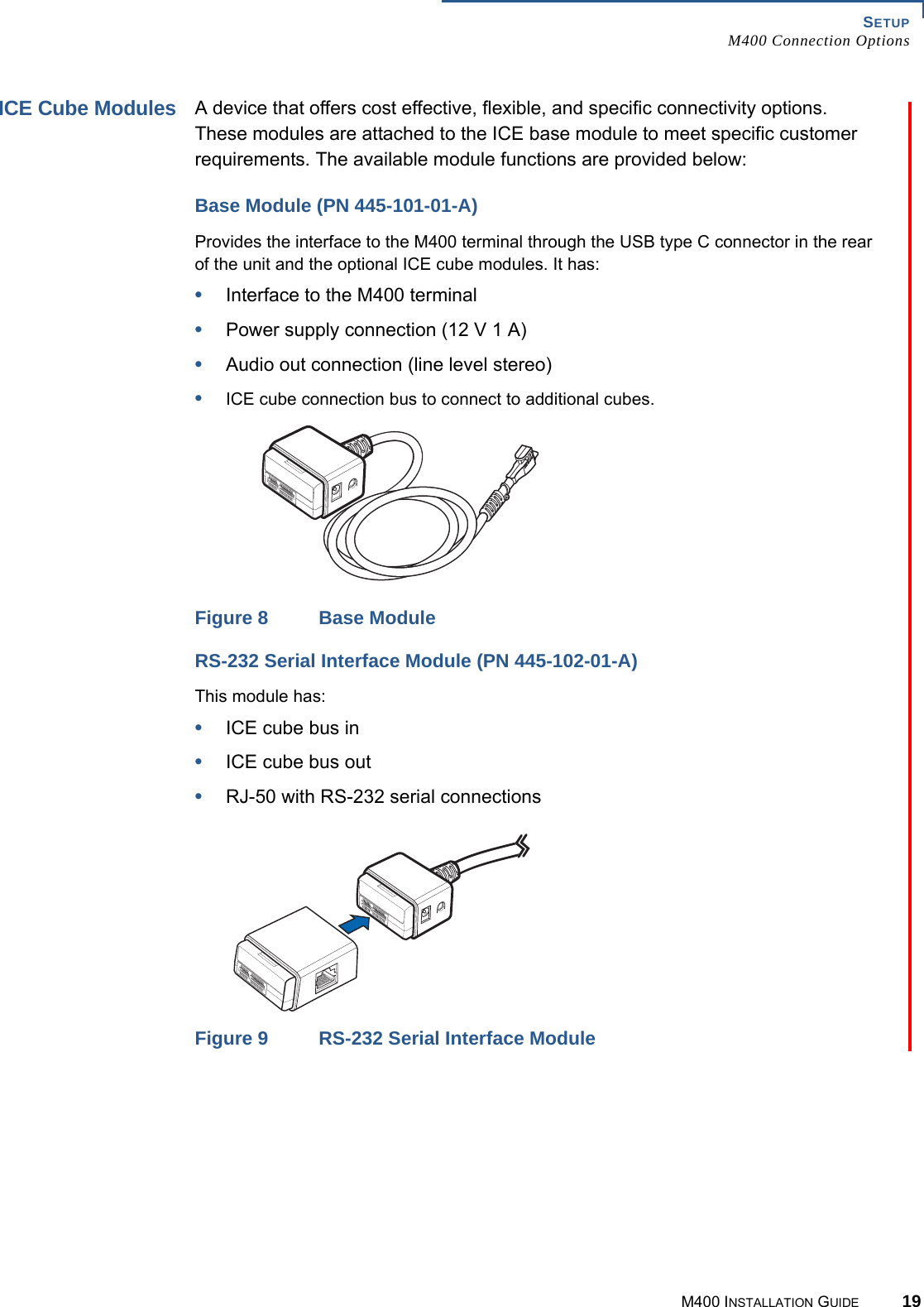
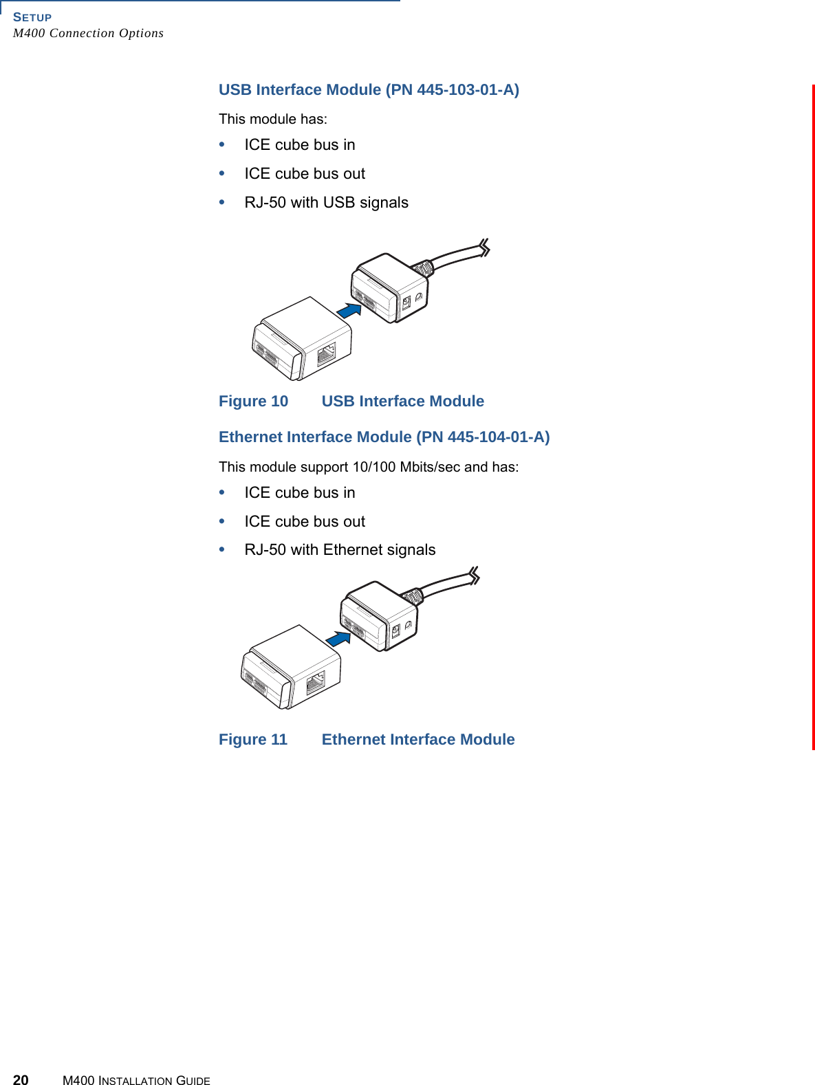
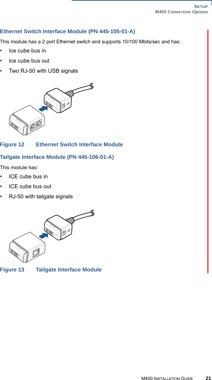
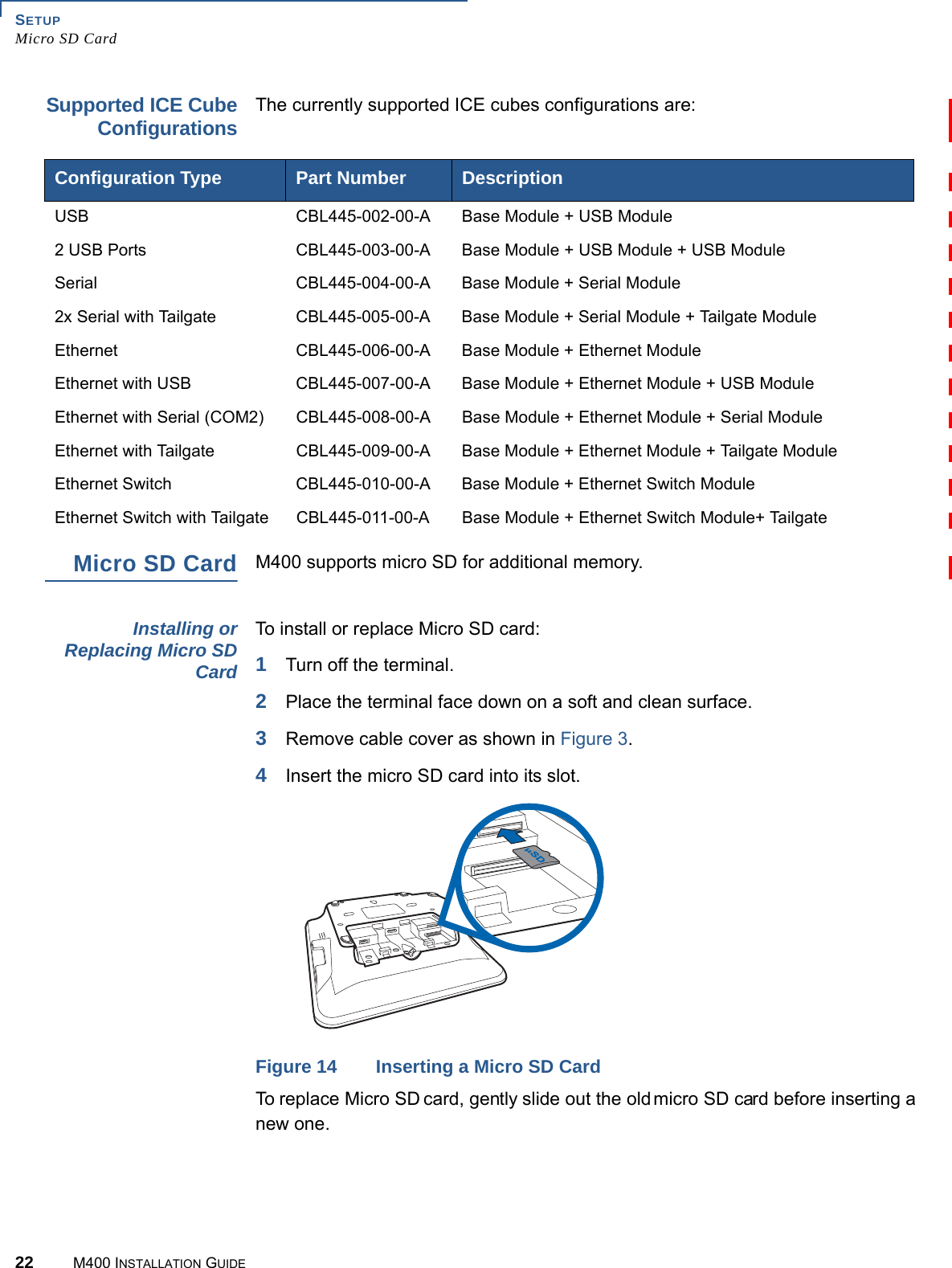
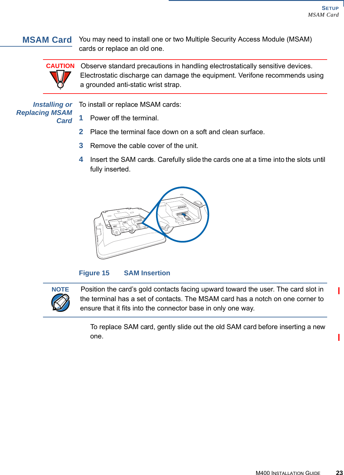
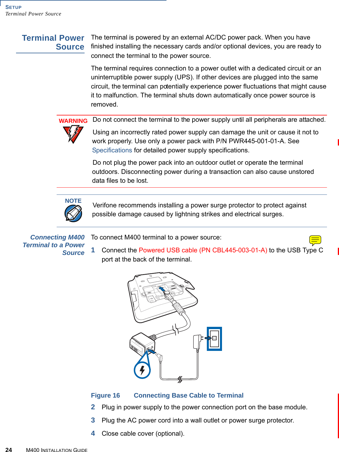
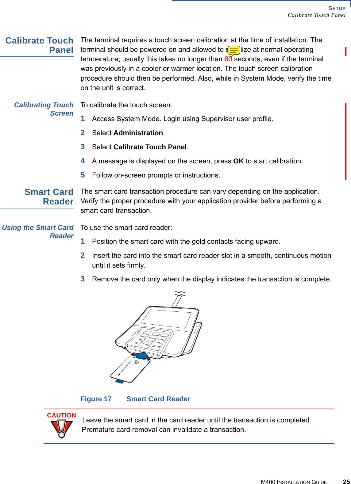
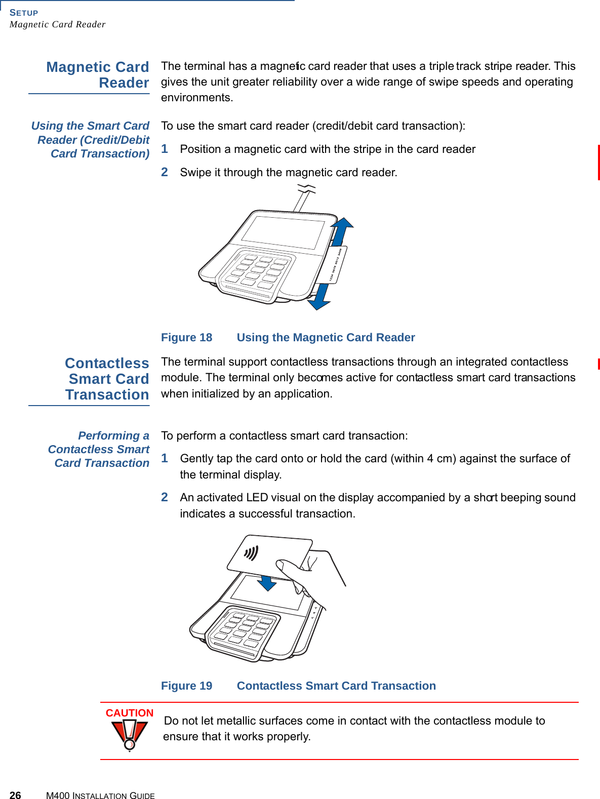
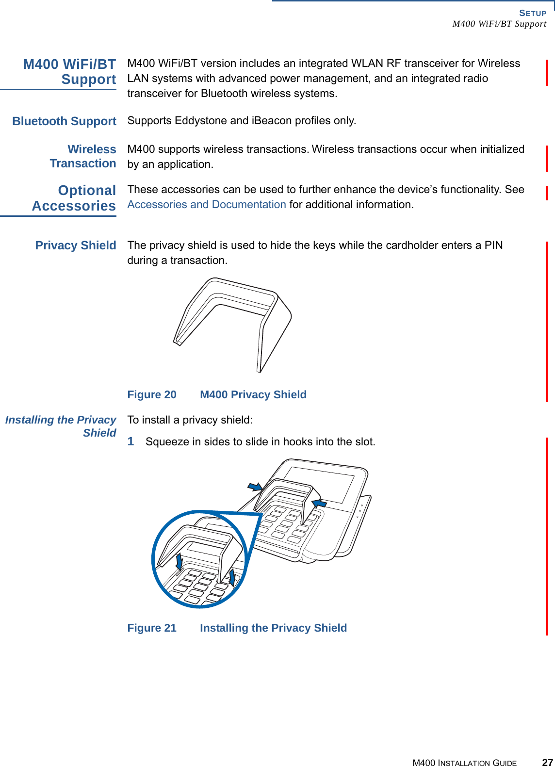
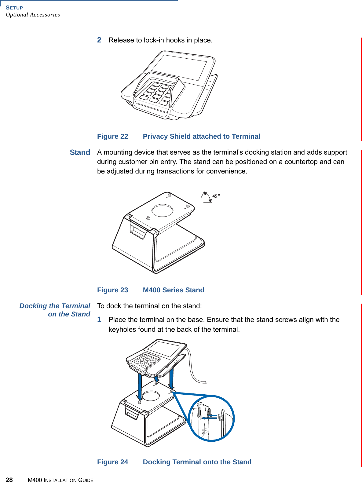
Users Manual
5.
Users Manual-Statement
Manual
Navigation menu
Upload a User Manual
Namespaces
Wiki Guide
HTML
PDF
Info
Views
User Manual
Discussion / Help
Navigation