Verifone M400WIFIBT Multilane Point of Sale Terminal User Manual M400 Installation Guide
VeriFone Inc Multilane Point of Sale Terminal M400 Installation Guide
Verifone >
Contents
Manual
Verifone Part Number DOC445-003-EN-A, Revision A.7
VER I FO N E
CONFID E NTIAL
REVISIO N A.7
M400
Installation Guide

All rights reserved . No p art of the con tents o f thi s documen t may be rep roduced or transmitte d in any form witho ut th e written
permission of Verifone, Inc.
The in formation cont ained in this d ocument is subj ect to chan ge wi thout notice. Alth ough Verifone ha s attempted to en sure the
accuracy of the contents of this document, this document may include errors or omissions. The examples and sample programs are
for illustration only and may not be suited for your purpose. You should verify the applicability of any example or sample program
before placing the software into productive use. This document, including without limitation the examples and software programs, is
supplied “As-Is.”
Verifone, Inc.
1-800-Verifone
www.verifone.com
Verifone Part Number DOC445-003-EN-A, Revision A.7
M400 Installation Guide
© 2017 Verifone, Inc.
Verifone, and the Verifone logo are registered trademarks of Verifone.
Other brand names or trademarks associated with Verifone’s products and services are trademarks of Verifone, Inc. All other brand
names and trademarks appearing in this manual are the property of their respective holders.
Product Warranty
For product warranty information, go to http://www.verifone.com/terms.
Comments? Please e-mail all comments in this document to your local Verifone Support Team.

M400 INSTALLATION GUIDE 3
CONTENTS
PREFACE . . . . . . . . . . . . . . . . . . . . . . . . . . . . . . . . . . . . . . . 5
Audience. . . . . . . . . . . . . . . . . . . . . . . . . . . . . . . . . . . . . . . . . . . . . . . . . . . . . . . . 5
Organization . . . . . . . . . . . . . . . . . . . . . . . . . . . . . . . . . . . . . . . . . . . . . . . . . . . . . 5
Related Documentation . . . . . . . . . . . . . . . . . . . . . . . . . . . . . . . . . . . . . . . . . . . . 5
Guide Conventions. . . . . . . . . . . . . . . . . . . . . . . . . . . . . . . . . . . . . . . . . . . . . . . . 6
Acronym Definitions . . . . . . . . . . . . . . . . . . . . . . . . . . . . . . . . . . . . . . . . . . . . 7
CHAPTER 1
Terminal Overview Features and Benefits . . . . . . . . . . . . . . . . . . . . . . . . . . . . . . . . . . . . . . . . . . . . 10
Exceptional Ease of Use. . . . . . . . . . . . . . . . . . . . . . . . . . . . . . . . . . . . . . . . 10
Performance and Durability . . . . . . . . . . . . . . . . . . . . . . . . . . . . . . . . . . . . . 10
Security . . . . . . . . . . . . . . . . . . . . . . . . . . . . . . . . . . . . . . . . . . . . . . . . . . . . . 10
Contactless Capability . . . . . . . . . . . . . . . . . . . . . . . . . . . . . . . . . . . . . . . . . 10
Communication Technology . . . . . . . . . . . . . . . . . . . . . . . . . . . . . . . . . . . . . 10
CHAPTER 2
Setup Terminal Location. . . . . . . . . . . . . . . . . . . . . . . . . . . . . . . . . . . . . . . . . . . . . . . . 11
Ease of Use . . . . . . . . . . . . . . . . . . . . . . . . . . . . . . . . . . . . . . . . . . . . . . . . . 11
Environmental Factors . . . . . . . . . . . . . . . . . . . . . . . . . . . . . . . . . . . . . . . . . 11
Electrical Considerations . . . . . . . . . . . . . . . . . . . . . . . . . . . . . . . . . . . . . . . 12
Contactless Considerations . . . . . . . . . . . . . . . . . . . . . . . . . . . . . . . . . . . . . 12
PIN Protection Measures . . . . . . . . . . . . . . . . . . . . . . . . . . . . . . . . . . . . . . . . . . 12
Ensuring User Privacy . . . . . . . . . . . . . . . . . . . . . . . . . . . . . . . . . . . . . . . . . 13
Mounting Considerations . . . . . . . . . . . . . . . . . . . . . . . . . . . . . . . . . . . . . . . 13
Inside the Shipping Carton . . . . . . . . . . . . . . . . . . . . . . . . . . . . . . . . . . . . . . . . . 14
Terminal Features . . . . . . . . . . . . . . . . . . . . . . . . . . . . . . . . . . . . . . . . . . . . . . . 15
Front Panel . . . . . . . . . . . . . . . . . . . . . . . . . . . . . . . . . . . . . . . . . . . . . . . . . . 15
Connection Ports . . . . . . . . . . . . . . . . . . . . . . . . . . . . . . . . . . . . . . . . . . . . . . . . 16
Connecting Cables and other Devices . . . . . . . . . . . . . . . . . . . . . . . . . . . . . 16
M400 Connection Options . . . . . . . . . . . . . . . . . . . . . . . . . . . . . . . . . . . . . . . . . 17
Powered USB Cable . . . . . . . . . . . . . . . . . . . . . . . . . . . . . . . . . . . . . . . . . . . 17
Berg Adaptor Cable . . . . . . . . . . . . . . . . . . . . . . . . . . . . . . . . . . . . . . . . . . . 17
ICE Cubes. . . . . . . . . . . . . . . . . . . . . . . . . . . . . . . . . . . . . . . . . . . . . . . . . . . 18
ICE Cube Modules . . . . . . . . . . . . . . . . . . . . . . . . . . . . . . . . . . . . . . . . . . . . 19
Supported ICE Cube Configurations. . . . . . . . . . . . . . . . . . . . . . . . . . . . . . . 22
Micro SD Card . . . . . . . . . . . . . . . . . . . . . . . . . . . . . . . . . . . . . . . . . . . . . . . . . . 22
MSAM Card . . . . . . . . . . . . . . . . . . . . . . . . . . . . . . . . . . . . . . . . . . . . . . . . . . . . 23
Terminal Power Source . . . . . . . . . . . . . . . . . . . . . . . . . . . . . . . . . . . . . . . . . . . 24
Calibrate Touch Panel . . . . . . . . . . . . . . . . . . . . . . . . . . . . . . . . . . . . . . . . . . . . 25
Smart Card Reader . . . . . . . . . . . . . . . . . . . . . . . . . . . . . . . . . . . . . . . . . . . . . . 25
Magnetic Card Reader . . . . . . . . . . . . . . . . . . . . . . . . . . . . . . . . . . . . . . . . . . . . 26
Contactless Smart Card Transaction . . . . . . . . . . . . . . . . . . . . . . . . . . . . . . . . . 26
M400 WiFi/BT Support . . . . . . . . . . . . . . . . . . . . . . . . . . . . . . . . . . . . . . . . . . . . 27
Bluetooth Support . . . . . . . . . . . . . . . . . . . . . . . . . . . . . . . . . . . . . . . . . . . . . 27
Wireless Transaction . . . . . . . . . . . . . . . . . . . . . . . . . . . . . . . . . . . . . . . . . . 27
Optional Accessories . . . . . . . . . . . . . . . . . . . . . . . . . . . . . . . . . . . . . . . . . . . . . 27

CONTENTS
4M400 INSTALLATION GUIDE
Privacy Shield . . . . . . . . . . . . . . . . . . . . . . . . . . . . . . . . . . . . . . . . . . . . . . . . 27
Stand. . . . . . . . . . . . . . . . . . . . . . . . . . . . . . . . . . . . . . . . . . . . . . . . . . . . . . . 28
External and Optional Devices . . . . . . . . . . . . . . . . . . . . . . . . . . . . . . . . . . . 30
CHAPTER 3
Specifications Power Rating . . . . . . . . . . . . . . . . . . . . . . . . . . . . . . . . . . . . . . . . . . . . . . . . . . . 31
Power Pack . . . . . . . . . . . . . . . . . . . . . . . . . . . . . . . . . . . . . . . . . . . . . . . . . . . . 31
Temperature . . . . . . . . . . . . . . . . . . . . . . . . . . . . . . . . . . . . . . . . . . . . . . . . . . . . 31
External Dimensions. . . . . . . . . . . . . . . . . . . . . . . . . . . . . . . . . . . . . . . . . . . . . . 31
Weight . . . . . . . . . . . . . . . . . . . . . . . . . . . . . . . . . . . . . . . . . . . . . . . . . . . . . . . . 31
Processor . . . . . . . . . . . . . . . . . . . . . . . . . . . . . . . . . . . . . . . . . . . . . . . . . . . . . . 31
Memory. . . . . . . . . . . . . . . . . . . . . . . . . . . . . . . . . . . . . . . . . . . . . . . . . . . . . . . . 31
Display . . . . . . . . . . . . . . . . . . . . . . . . . . . . . . . . . . . . . . . . . . . . . . . . . . . . . . . . 31
Magnetic Card Reader . . . . . . . . . . . . . . . . . . . . . . . . . . . . . . . . . . . . . . . . . . . . 31
Primary Smart Card . . . . . . . . . . . . . . . . . . . . . . . . . . . . . . . . . . . . . . . . . . . . . . 31
SAM Card Reader . . . . . . . . . . . . . . . . . . . . . . . . . . . . . . . . . . . . . . . . . . . . . . . 32
SD Card Reader . . . . . . . . . . . . . . . . . . . . . . . . . . . . . . . . . . . . . . . . . . . . . . . . . 32
Integrated Contactless Reader. . . . . . . . . . . . . . . . . . . . . . . . . . . . . . . . . . . . . . 32
Keypad . . . . . . . . . . . . . . . . . . . . . . . . . . . . . . . . . . . . . . . . . . . . . . . . . . . . . . . . 32
Audio Jack . . . . . . . . . . . . . . . . . . . . . . . . . . . . . . . . . . . . . . . . . . . . . . . . . . . . . 32
Peripheral Ports . . . . . . . . . . . . . . . . . . . . . . . . . . . . . . . . . . . . . . . . . . . . . . . . . 32
Security. . . . . . . . . . . . . . . . . . . . . . . . . . . . . . . . . . . . . . . . . . . . . . . . . . . . . . . . 32
CHAPTER 4
Maintenance and
Cleaning Additional Safety Information . . . . . . . . . . . . . . . . . . . . . . . . . . . . . . . . . . . . . . . 34
Power Adapter . . . . . . . . . . . . . . . . . . . . . . . . . . . . . . . . . . . . . . . . . . . . . . . 34
Potentially Explosive Environments . . . . . . . . . . . . . . . . . . . . . . . . . . . . . . . 34
Magnetic Stripe Cleaner . . . . . . . . . . . . . . . . . . . . . . . . . . . . . . . . . . . . . . . . 34
Smart Card Cleaner . . . . . . . . . . . . . . . . . . . . . . . . . . . . . . . . . . . . . . . . . . . 34
CHAPTER 5
Service and Support Service Returns . . . . . . . . . . . . . . . . . . . . . . . . . . . . . . . . . . . . . . . . . . . . . . . . . 37
Accessories and Documentation . . . . . . . . . . . . . . . . . . . . . . . . . . . . . . . . . . . . 38
CHAPTER 6
Troubleshooting
Guidelines Terminal Does Not Start . . . . . . . . . . . . . . . . . . . . . . . . . . . . . . . . . . . . . . . . . . . 41
Terminal Display Does Not Show Correct/Readable Info. . . . . . . . . . . . . . . . . . 41
Blank Display . . . . . . . . . . . . . . . . . . . . . . . . . . . . . . . . . . . . . . . . . . . . . . . . . . . 42
Keypad Does Not Respond . . . . . . . . . . . . . . . . . . . . . . . . . . . . . . . . . . . . . . . . 42
Transactions Fail To Process . . . . . . . . . . . . . . . . . . . . . . . . . . . . . . . . . . . . . . . 42

M400 INSTALLATION GUIDE 5
PREFACE
This guide is the primary source of information for setting up and installing the
terminal.
Audience
This guide is useful to anyone installing and configuring the terminal.
Organization
This guide is organized as follows:
Chapter 1, Terminal Overview. Provides an overview of the terminal.
Chapter 2, Setup. Explains setup and installation of the terminal, selecting a
location, and establishing connections with other devices.
Chapter 3, Specifications. Discusses power requirements and dimensions of the
terminal.
Chapter 4, Maintenance and Cleaning. Explains maintenance of the terminal.
Chapter 5, Service and Support. Provides information on contacting your Verifone
service provider and information on how to order accessories or documentations
from Verifone.
Chapter 6, Troubleshooting Guidelines. Provides troubleshooting guidelines
should you encounter a problem in terminal installation and configuration.
Related
Documentation
Refer to the following set of documents to learn more about the terminal:
M400 Certifications and Regulations VPN - DOC445-001-EN
M400 Series Quick Installation Guide VPN - DOC445-002-EN
M400 Series Ice Cube Certifications and Regulations VPN - DOC445-005-EN
M400 Series Ice Cube Quick Installation Guide VPN - DOC445-006-EN
M400 Series Stand Quick Installation Guide VPN - DOC445-007-EN
M400 Series Privacy Shield Quick Installation Guide VPN - DOC445-008-EN
VOS Programmers Manual VPN - DOC00501
PREFACE
Guide Conventions
6M400 INSTALLATION GUIDE
Guide
Conventions
Various conventions are used to help you quickly identify special formatting.
Table 1 describes these conventions and provides examples of their use.
Table 1 Document Conventions
Convention Meaning Example
Blue Text in blue indicates terms that
are cross references.
See Guide Conventions.
Italics Italic typeface indicates book
titles or emphasis.
You must not use this unit
underwater.
The pencil icon is used to
highlight important information.
RS232-type devices do not work
on the M400 communication
port.
The caution symbol indicates
hardware or software failure, or
loss of data.
The unit is not waterproof or
dustproof, and is intended for
indoor use only.
The lightning symbol is used as a
warning when bodily injury might
occur.
Do not use the terminal near
water due to risk of shock.
NOTE
CAUTION
WARNING

PREFACE
Guide Conventions
M400 INSTALLATION GUIDE 7
Acronym Definitions
Acronyms are used in place of the full definition. Table 2 presents acronyms and
their definitions.
Table 2 Acronym Definitions
Acronym Definitions
3DES Triple Data Encryption Standard
AES Advanced Encryption Standard Algorithm
API Application Programming Interface
ARM Advanced RISC Machine
BBM Battery Backed Memory
CAPK Certification Authority Public Key
CBC Cipher Block Chaining mode
DEA/DES Data Encryption Algorithm/Standard
DUKPT Derived Unique Key Per Transaction Method as defined in the
VISA’s POS Equipment Requirement: PIN processing and Data
Authentication, International Version 1.0, August 1988
ECR Electronic Cash Register
EMV Joint Europay, MasterCard and Visa Standard
FSM Fiscal Module
MAC Message Authentication Code
MMU Memory Management Unit
MSAM Multiple Secure Access Module
OS Operating System
PIN Personal Identification Number
POS Point-of-Sale
RFID Radio Frequency Identification
SAM Secure Access Module
SC Smart Card (Integrated Chip Card)
SD Secure Digital
SR Ship Release
SRAM Static Random Access Memory
UI User Interface
USB Universal Serial Bus
Wi-Fi Wireless Fidelity

PREFACE
Guide Conventions
8M400 INSTALLATION GUIDE
M400 INSTALLATION GUIDE 9
CHAPTER 1
Terminal
Overview
A media-capable consumer-facing device that connects to a POS system which
allows electronic payment transactions to be processed in multi-lane scenarios. It
provides better media capabilities, more reliable hardware, and more efficient
processing software.
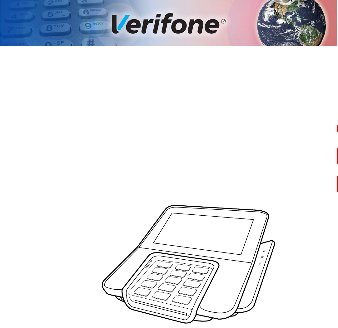
The terminal features a color 5” IPS LCD capacitive touch screen display, fast
processor, abundant memory, PCI 4.x security, and an integrated contactless
module. M400 WiFi/BT supports 802.11 a/b/g/n Wireless Fidelity (Wi-Fi) and
Bluetooth (BT), while the M400 BT variant supports Bluetooth (BT) including BLE
with iBeacon and Eddystone profiles .
Figure 1 M400 Terminal

TERMINAL OVERVIEW
Features and Benefits
10 M400 INSTALLATION GUIDE
Features and
Benefits
The terminal focuses on optimizing cost structure and providing better form factor
by combining the right features and functions.
Exceptional Ease of
Use
•Large 5” LCD display for unlimited application possibilities and easy
readability under various lighting conditions.
•Touchscreen for icon-based applications or electronic signature capture
support.
•Intuitive telco-style keypad with colored control keys, interchangeably detects
key presses from tactile keypad and the touchscreen.
•Bi-directional magnetic stripe card reader with an extended blade for optimal
card reading.
•Audio jack to facilitate accessibility for the visually impaired.
Performance and
Durability
•Fast transactions due to powerful 1 GHz ARM Cortex A9 processor.
•Rounded corners and drop resistant to three feet on concrete floor to minimize
breakage.
•256 MB of flash memory and 512 MB SDRAM with removable uSD.
Security
•Incorporates tamper-detection circuitry to resist unauthorized intrusion and
supports a broad spectrum of software-based security features.
•PCI 4.x approved for debit and other PIN-based transactions.
•EMV Level 1 Type Approval.
•Supports reliable security available including SSL, VeriShield file
authentication, and VeriShield Protect to help prevent fraud and other
intrusions.
•With Kensington lock feature resident in the terminal as part of the case.
Contactless
Capability
•Advanced contactless architecture that future-proofs investment with a single
contactless interface (SingleCl), SoftSAMs, and side-by-side application
architecture.
•On-screen tap zone for optimized user experience.
•Accepts EMV, NFC, and mag-stripe contactless payments as well as PIN-
based transactions.
Communication
Technology
•Bluetooth: Simple, plug-and-play installation for locations that need short-
range wireless capability. Eddystone and iBeacon profiles are also supported.
•Wi-Fi: Ideal for retailers that need multiple wireless devices and have an
existing IP infrastructure (M400 WiFi-BT only).

M400 INSTALLATION GUIDE 11
CHAPTER 2
Setup
This chapter describes the setup procedure for:
•Terminal Location.
•Inside the Shipping Carton.
•Terminal Features.
•Connection Ports.
•M400 Connection Options.
•MSAM Card.
•Terminal Power Source.
•Calibrate Touch Panel.
•Smart Card Reader.
•Magnetic Card Reader.
•Contactless Smart Card Transaction.
•M400 WiFi/BT Support.
•Optional Accessories.
Terminal
Location
The following are guidelines used to select an ideal location for the terminal.
Ease of Use
•Select a location convenient for both merchant and cardholder.
•Select a flat support surface, such as a countertop or table, or mount it on a
mounting stand supplied by Verifone.
•Select a location near a power outlet, POS, ECR, or computer connected to
the terminal. Do not string cables or cords across a walkway for safety.
Environmental
Factors
•Do not use the unit where there is high heat, dust, humidity, moisture, caustic
chemicals or oils.
•Keep the unit away from direct sunlight and anything that radiates heat, such
as a stove or a motor.
•Do not use the terminal outdoors.
SETUP
PIN Protection Measures
12 M400 INSTALLATION GUIDE
Electrical
Considerations
•Avoid using this product during electrical storms.
•Avoid locations near electrical appliances or other devices that cause
excessive voltage fluctuations or emit electrical noise (for example, air
conditioners, electric motors, neon signs, high-frequency or magnetic security
devices, or computer equipment).
•Do not use the terminal near water or in moist conditions.
•Disconnect the device from its POS terminal before cleaning.
Contactless
Considerations Avoid having metallic objects in proximity of the contactless antenna. If you need
to mount the terminal to vertical or inclined surfaces, use a flat, non-metallic
mounting plate.
PIN Protection
Measures
Use the following techniques to provide effective screening of PIN-Entry Devices
(PEDs) during the PIN-entry process. You can use these methods in combination,
although in some cases a single method might suffice.
•Position the terminal on the check-in stand in such a way as to block visual
observation of the PIN-entry process. Examples include:
•Visual shields designed into the check-in stand. The shields may be solely
for shielding purposes, or may be part of the general check-in stand
design.
•Position the terminal so that it is angled in such a way that PIN spying is
difficult.
•Install the PED on an adjustable stand that allows consumers to swivel the
terminal sideways and/or tilt it forwards/backwards to a position that makes
visual observation of the PIN-entry process difficult.
•Position in-store security cameras so that the PIN-entry keypad is not visible.
CAUTION
The terminal is not waterproof or dustproof. It is intended for indoor use only. Any
damage to the unit from exposure to rain or dust can void any warranty.
WARNING
Do not use the terminal near water, including a bathtub, wash bowl, kitchen sink
or laundry tub, in a wet basement, or near a swimming pool to avoid shock or
damage.
CAUTION
Using an enclosed metal frame or mount may negatively affect contactless
performance

SETUP
PIN Protection Measures
M400 INSTALLATION GUIDE 13
The following table describes the two preferred mounting methods and the
recommended measures to protect against PIN capture in four observation
corridors:
Verifone also recommends instruction of the cardholder regarding safe PIN-entry.
This can be done with a combination of:
•Signage on the PED
•Prompts on the display, possibly with a click-through screen
•Literature at the point of sale
•A logo for safe PIN-entry process.
Ensuring User
Privacy
Use the following guidelines to protect the user’s privacy when he enters his
personal identification number (PIN):
•The area of visibility should be no larger than a cone taken from the number 5
key at an angle of 45° and covering an area of 270° directly in front of the user.
•You can secure PIN entry by installing a Privacy Shield (optional).
Mounting
Considerations
Verifone recommends the use of an approved stand for all mounting situations.
Position the terminal conveniently in relation to power, POS, ECR, and LAN
connections. Ensure the M400 terminal is located in a manner that allows
customers to swipe their magnetic cards or insert their Smart Cards in a smooth
and comfortable motion without encountering obstructions. If the unit will be
swiveled during normal operation, Verifone requires the use of an approved swivel
stand.
Table 3 Mounting Methods and Protection Measures
Method Cashier Customer in
Queue Customers
Elsewhere On-site
Cameras
Countertop
without stand
Use signage
behind the
PED
Install so that
customer is
between PED and
next in queue
No action
needed
Do not install
within view of
cameras
Countertop
with stand
No action
needed
Install so that
customer is
between PED and
next in queue
No action
needed
Do not install
within view of
cameras
NOTE
Special care is required when mounting the M400 terminal in sites that utilize
anti-theft devices positioned at doorways or surface mounted deactivator pads.
Devices of this type, such as Sensormatic brand devices, generate strong
electromagnetic fields which may interfere with M400 terminal. Always select
mounting locations at least six feet from doorway units and at least 18 inches
from surface mounted deactivator pads.
SETUP
Inside the Shipping Carton
14 M400 INSTALLATION GUIDE
Inside the
Shipping Carton
Open the shipping carton and carefully inspect its contents for possible tampering
or shipping damage. The terminal is a secure product. Tampering causes it to
cease to function or to operate in an unsecured manner.
Unpacking the
Shipping Carton To unpack the shipping carton:
1Remove and inspect the contents of the shipping carton. The terminal ships in
multiple configurations, the carton may include all or any of the following:
•Terminal
•Connectivity cable
2Remove all plastic wrapping from the terminal and components.
3Remove the clear protective film from the display.
4Save the shipping carton and packing material for future repacking or moving
of the device.
NOTE
Power supply, connectivity cubes, and base module are shipped separately or
depending on customer requirements.
WARNING
Do not use a tampered or damaged unit. The terminal comes equipped with
tamper-evident labels. If a label or component appears damaged, please notify
the shipping company and your Verifone service provider immediately.
SETUP
Terminal Features
M400 INSTALLATION GUIDE 15
Terminal
Features
Familiarize yourself with the terminal features before continuing with the
installation process:
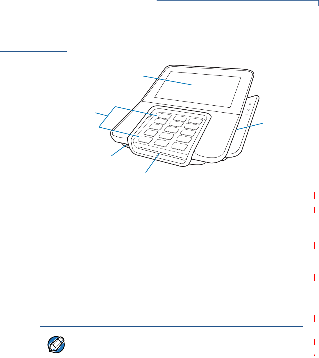
Figure 2 M400 Features
Front Panel
The front panel offers the following features:
•A touchscreen display.
•A set of keys that include:
•A 12-key, telco-style keypad (keypads may vary in style).
•Three function keys at the bottom of the keypad (from left to right:
CANCEL, CLEAR, ENTER).
•A magnetic card reader, built into the right side. LEDs shows the proper swipe
direction, with the stripe facing down and towards the keypad.
•A smart card reader, built into the unit’s front side. An icon indicates the proper
card position and insertion direction.
•A 3.5 mm audio jack to facilitate accessibility for the visually impaired.
TELCO-STYLE
KEYPAD
TOUCH SCREEN DISPLAY
AUDIO JACK
SMART CARD READER
MAGNETIC CARD
READER
NOTE
On screen PIN entry is NOT supported.
SETUP
Connection Ports
16 M400 INSTALLATION GUIDE
Connection
Ports
The terminal has two ports available: USB Type C port for power and
communications connection, and a Micro-USB port connector.
Connecting Cables
and other Devices
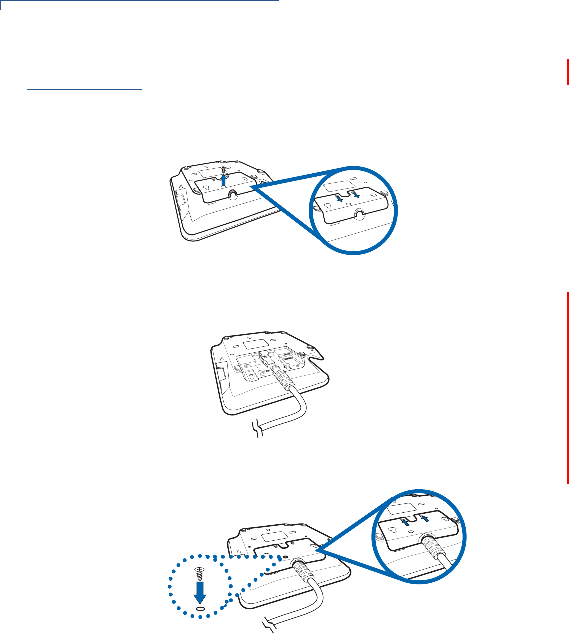
To connect required cable connections and other devices:
1Unscrew and remove cable cover as shown below.
Figure 3 Removing Cable Cover
2Connect required cable connections or optional devices. Attaching the USB C
Cable provides multiple connection options. See Figure 7 for reference.
Figure 4 USB Type C Cable Connected on the Rear of the Unit
3Close cable compartment as shown below (optional).
Figure 5 Closing Cable Compartment with Cable Cover
SETUP
M400 Connection Options
M400 INSTALLATION GUIDE 17
M400
Connection
Options
The M400 terminal can be connected to other systems using several methods.
They all connect to the M400 using the USB Type C cable connected on the rear
of the unit.
Powered USB Cable
Powered USB cable (PN CBL445-003-01-A) provides USB signal connectivity
and power. It provides a convenient way of connecting other systems of the same
type.
Figure 6 Powered USB Cable (USB Type C)
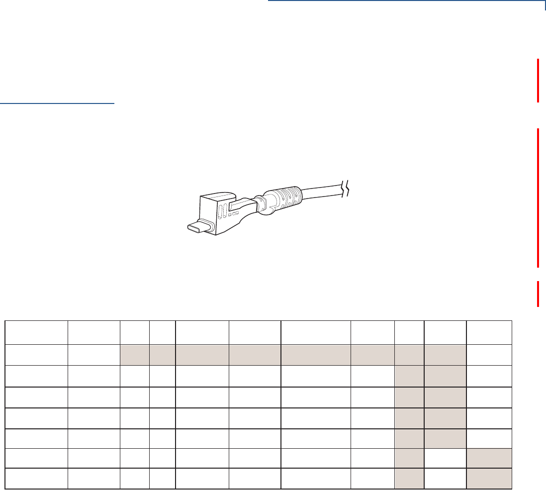
Berg Adaptor Cable
Berg adaptor cable (PN CBL445-100-01-A) connects the M400 terminal to legacy
berg connection systems. M400 supports the following Berg cables.
Verifone Cable
P/N Cable Color Power Audio COM1 COM2 Tailgate/
COM3
10BT
Ethernet PoE USB 1.1
Host
USB 1.1
Device
23998-02-R Yellow
24173-02-R Purple
1 (Powered
USB)
23741-02-R Blue
23745-02-R Brown
26838-02-R White
23739-02-R Red
223740-02-R Green
1
1
1
1
1
1
1
1
1
1
1
1
1 (RJ-45) 1 Tailgate (Female
SDL-4)
1 COM3 (RJ-45)1 (RJ-45)
1 (RJ-45)
1 (RJ-45)
1 (RJ-45)
1 (RJ-45)
1 (RJ-45)
1 (RJ-45)
1 (RJ-45)
1 (RJ-45)
1 (RJ-45)
1 (RJ-45)
1 Tailgate (Female
SDL-4)
1 COM3 (RJ-45)
1 Tailgate (Male
SDL-4)
1 COM3 (Male
DB9)
3 (RJ-45)
1 (RJ-45)
1 (RJ-45)
1 (RJ-45)
1 (RJ-45)
1 (RJ-45)
1 (Type A)
1 (Type A)
1 (RJ-45)
1 (Type A)
1 (RJ-45)
1 (Powered
USB)
SETUP
M400 Connection Options
18 M400 INSTALLATION GUIDE
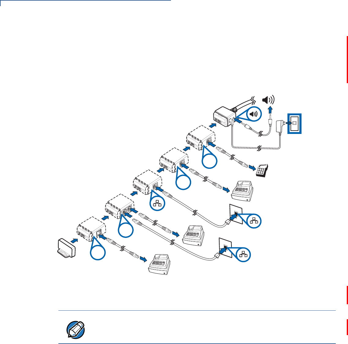
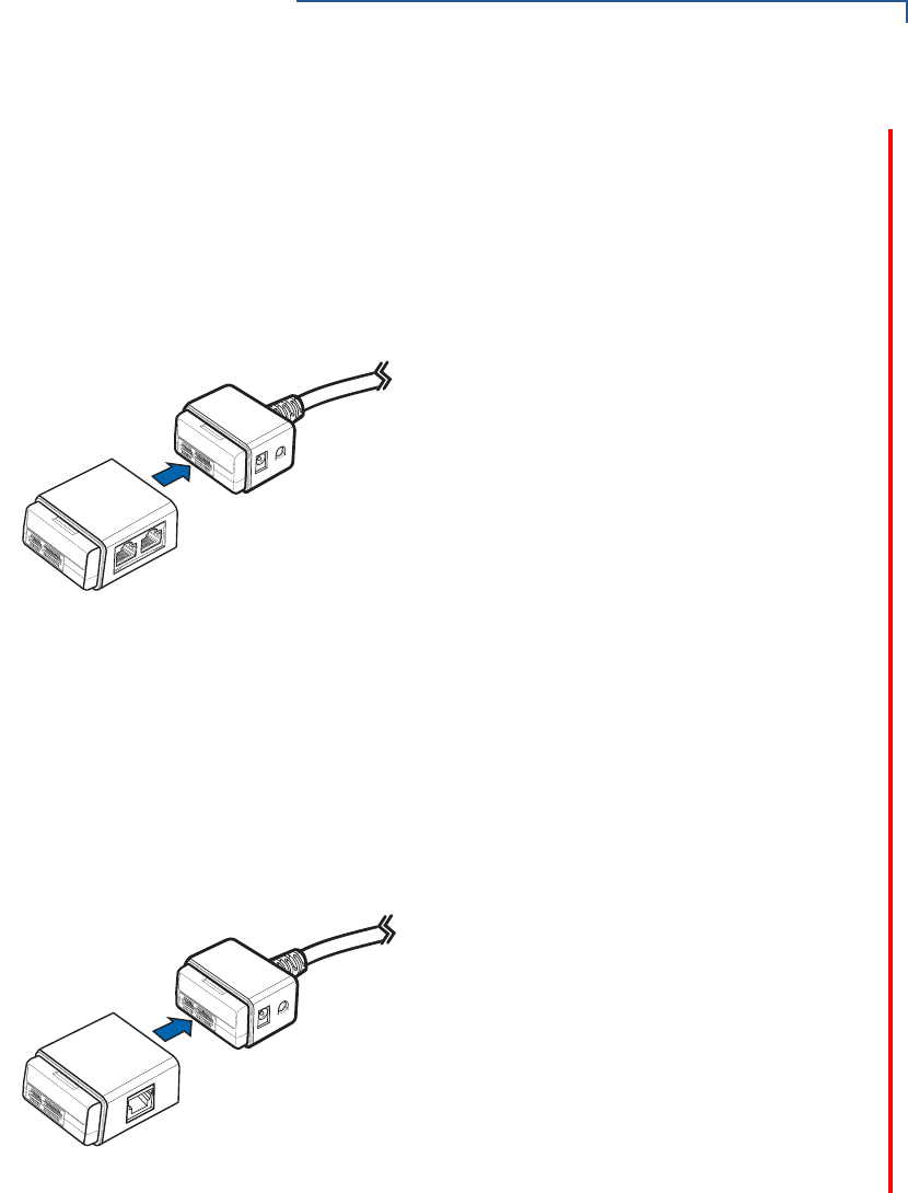
ICE Cubes
A set of modules that allow easy, economical, and efficient custom configuration
of communications options.
Each configuration is comprised of a base module, an end cap, and a combination
of other modules that support different communications interfaces, see Figure 7
as an example.
Figure 7 Sample ICE Cube Assembly
Refer to ICE Cube Modules for more information.
COM
Ethernet
Switch
Tailgate
USB
NOTE
Appearance and number of ICE Cubes vary depending on customer
requirements.
SETUP
M400 Connection Options
M400 INSTALLATION GUIDE 19
ICE Cube Modules
A device that offers cost effective, flexible, and specific connectivity options.
These modules are attached to the ICE base module to meet specific customer
requirements. The available module functions are provided below:
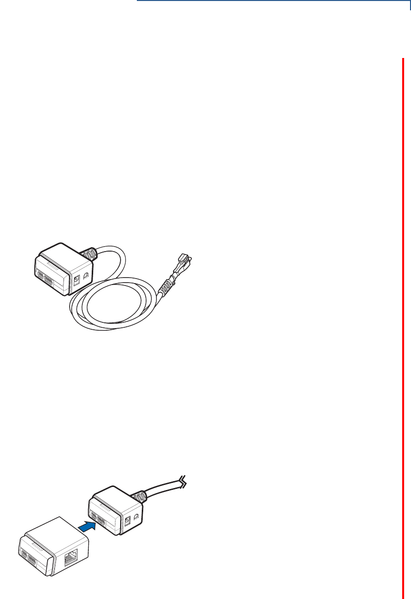
Base Module (PN 445-101-01-A)
Provides the interface to the M400 terminal through the USB type C connector in the rear
of the unit and the optional ICE cube modules. It has:
•Interface to the M400 terminal
•Power supply connection (12 V 1 A)
•Audio out connection (line level stereo)
•ICE cube connection bus to connect to additional cubes.
Figure 8 Base Module
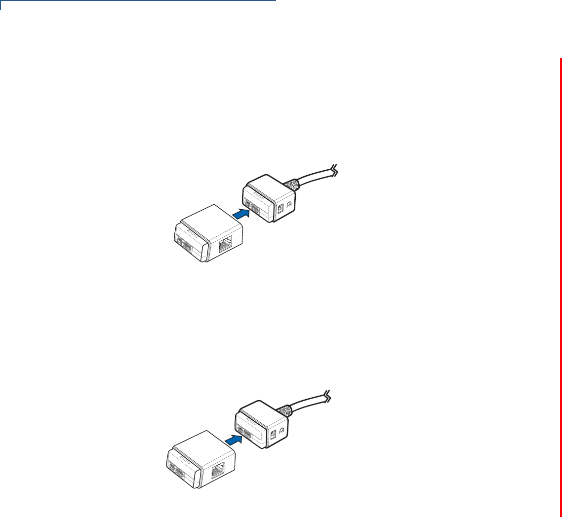
RS-232 Serial Interface Module (PN 445-102-01-A)
This module has:
•ICE cube bus in
•ICE cube bus out
•RJ-50 with RS-232 serial connections
Figure 9 RS-232 Serial Interface Module
SETUP
M400 Connection Options
20 M400 INSTALLATION GUIDE
USB Interface Module (PN 445-103-01-A)
This module has:
•ICE cube bus in
•ICE cube bus out
•RJ-50 with USB signals
Figure 10 USB Interface Module
Ethernet Interface Module (PN 445-104-01-A)
This module support 10/100 Mbits/sec and has:
•ICE cube bus in
•ICE cube bus out
•RJ-50 with Ethernet signals
Figure 11 Ethernet Interface Module
SETUP
M400 Connection Options
M400 INSTALLATION GUIDE 21
Ethernet Switch Interface Module (PN 445-105-01-A)
This module has a 2 port Ethernet switch and supports 10/100 Mbits/sec and has:
•Ice cube bus in
•Ice cube bus out
•Two RJ-50 with USB signals
Figure 12 Ethernet Switch Interface Module
Tailgate Interface Module (PN 445-106-01-A)
This module has:
•ICE cube bus in
•ICE cube bus out
•RJ-50 with tailgate signals
Figure 13 Tailgate Interface Module
SETUP
Micro SD Card
22 M400 INSTALLATION GUIDE
Supported ICE Cube
Configurations
The currently supported ICE cubes configurations are:
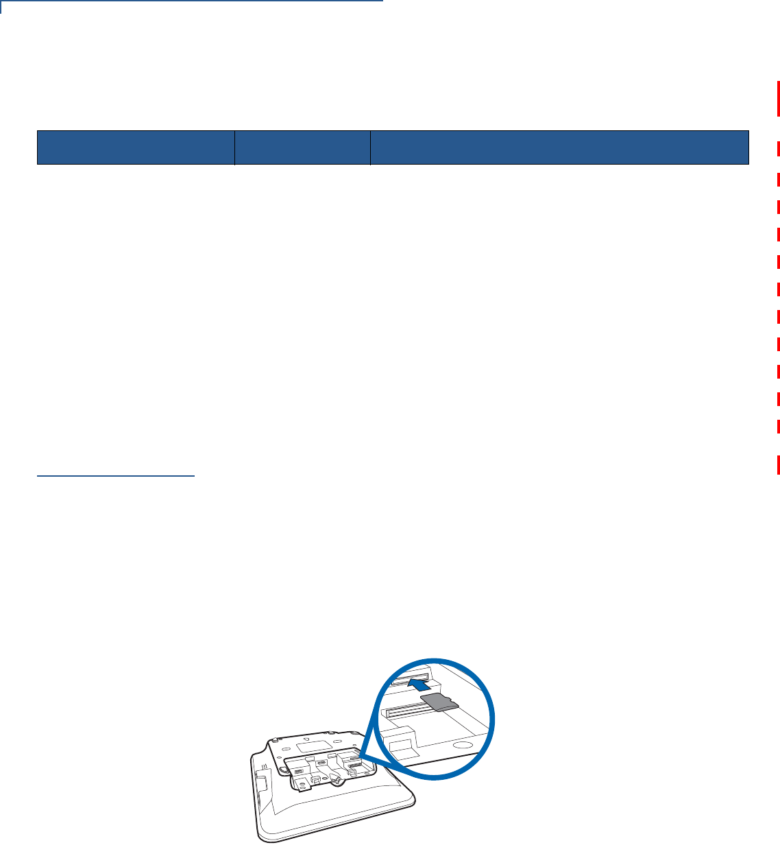
Micro SD Card
M400 supports micro SD for additional memory.
Installing or
Replacing Micro SD
Card
To install or replace Micro SD card:
1Turn off the terminal.
2Place the terminal face down on a soft and clean surface.
3Remove cable cover as shown in Figure 3.
4Insert the micro SD card into its slot.
Figure 14 Inserting a Micro SD Card
To replace Micro SD card, gently slide out the old micro SD card before inserting a
new one.
Configuration Type Part Number Description
USB CBL445-002-00-A Base Module + USB Module
2 USB Ports CBL445-003-00-A Base Module + USB Module + USB Module
Serial CBL445-004-00-A Base Module + Serial Module
2x Serial with Tailgate CBL445-005-00-A Base Module + Serial Module + Tailgate Module
Ethernet CBL445-006-00-A Base Module + Ethernet Module
Ethernet with USB CBL445-007-00-A Base Module + Ethernet Module + USB Module
Ethernet with Serial (COM2) CBL445-008-00-A Base Module + Ethernet Module + Serial Module
Ethernet with Tailgate CBL445-009-00-A Base Module + Ethernet Module + Tailgate Module
Ethernet Switch CBL445-010-00-A Base Module + Ethernet Switch Module
Ethernet Switch with Tailgate CBL445-011-00-A Base Module + Ethernet Switch Module+ Tailgate
μ
SD
SETUP
MSAM Card
M400 INSTALLATION GUIDE 23
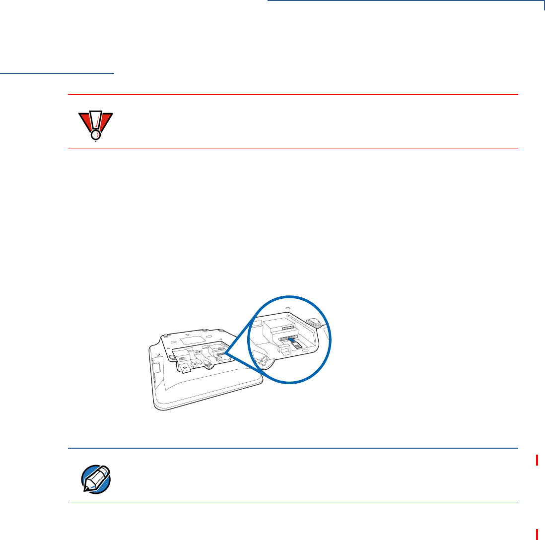
MSAM Card
You may need to install one or two Multiple Security Access Module (MSAM)
cards or replace an old one.
Installing or
Replacing MSAM
Card
To install or replace MSAM cards:
1Power off the terminal.
2Place the terminal face down on a soft and clean surface.
3Remove the cable cover of the unit.
4Insert the SAM cards. Carefully slide the cards one at a time into the slots until
fully inserted.
Figure 15 SAM Insertion
To replace SAM card, gently slide out the old SAM card before inserting a new
one.
CAUTION
Observe standard precautions in handling electrostatically sensitive devices.
Electrostatic discharge can damage the equipment. Verifone recommends using
a grounded anti-static wrist strap.
NOTE
Position the card’s gold contacts facing upward toward the user. The card slot in
the terminal has a set of contacts. The MSAM card has a notch on one corner to
ensure that it fits into the connector base in only one way.
SETUP
Terminal Power Source
24 M400 INSTALLATION GUIDE
Terminal Power
Source
The terminal is powered by an external AC/DC power pack. When you have
finished installing the necessary cards and/or optional devices, you are ready to
connect the terminal to the power source.
The terminal requires connection to a power outlet with a dedicated circuit or an
uninterruptible power supply (UPS). If other devices are plugged into the same
circuit, the terminal can potentially experience power fluctuations that might cause
it to malfunction. The terminal shuts down automatically once power source is
removed.
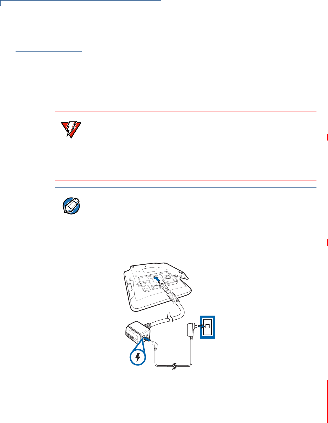
Connecting M400
Terminal to a Power
Source
To connect M400 terminal to a power source:
1Connect the Powered USB cable (PN CBL445-003-01-A) to the USB Type C
port at the back of the terminal.
Figure 16 Connecting Base Cable to Terminal
2Plug in power supply to the power connection port on the base module.
3Plug the AC power cord into a wall outlet or power surge protector.
4Close cable cover (optional).
WARNING
Do not connect the terminal to the power supply until all peripherals are attached.
Using an incorrectly rated power supply can damage the unit or cause it not to
work properly. Use only a power pack with P/N PWR445-001-01-A. See
Specifications for detailed power supply specifications.
Do not plug the power pack into an outdoor outlet or operate the terminal
outdoors. Disconnecting power during a transaction can also cause unstored
data files to be lost.
NOTE
Verifone recommends installing a power surge protector to protect against
possible damage caused by lightning strikes and electrical surges.
SETUP
Calibrate Touch Panel
M400 INSTALLATION GUIDE 25
Calibrate Touch
Panel
The terminal requires a touch screen calibration at the time of installation. The
terminal should be powered on and allowed to stabilize at normal operating
temperature; usually this takes no longer than 60 seconds, even if the terminal
was previously in a cooler or warmer location. The touch screen calibration
procedure should then be performed. Also, while in System Mode, verify the time
on the unit is correct.
Calibrating Touch
Screen To calibrate the touch screen:
1Access System Mode. Login using Supervisor user profile.
2Select Administration.
3Select Calibrate Touch Panel.
4A message is displayed on the screen, press OK to start calibration.
5Follow on-screen prompts or instructions.
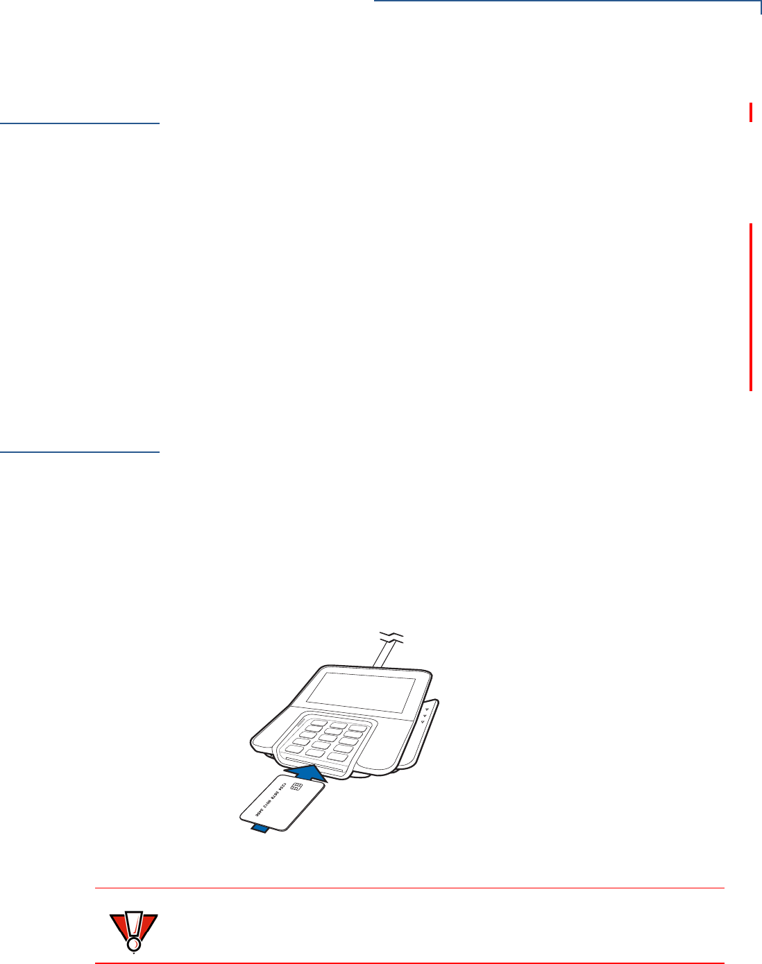
Smart Card
Reader
The smart card transaction procedure can vary depending on the application.
Verify the proper procedure with your application provider before performing a
smart card transaction.
Using the Smart Card
Reader To use the smart card reader:
1Position the smart card with the gold contacts facing upward.
2Insert the card into the smart card reader slot in a smooth, continuous motion
until it sets firmly.
3Remove the card only when the display indicates the transaction is complete.
Figure 17 Smart Card Reader
CAUTION
Leave the smart card in the card reader until the transaction is completed.
Premature card removal can invalidate a transaction.
SETUP
Magnetic Card Reader
26 M400 INSTALLATION GUIDE
Magnetic Card
Reader
The terminal has a magnetic card reader that uses a triple track stripe reader. This
gives the unit greater reliability over a wide range of swipe speeds and operating
environments.
Using the Smart Card
Reader (Credit/Debit
Card Transaction)
To use the smart card reader (credit/debit card transaction):
1Position a magnetic card with the stripe in the card reader
2Swipe it through the magnetic card reader.
Figure 18 Using the Magnetic Card Reader
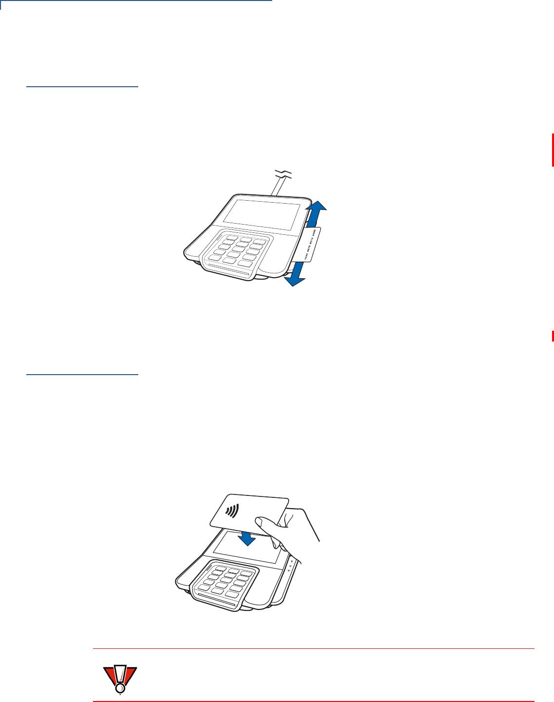
Contactless
Smart Card
Transaction
The terminal support contactless transactions through an integrated contactless
module. The terminal only becomes active for contactless smart card transactions
when initialized by an application.
Performing a
Contactless Smart
Card Transaction
To perform a contactless smart card transaction:
1Gently tap the card onto or hold the card (within 4 cm) against the surface of
the terminal display.
2An activated LED visual on the display accompanied by a short beeping sound
indicates a successful transaction.
Figure 19 Contactless Smart Card Transaction
CAUTION
Do not let metallic surfaces come in contact with the contactless module to
ensure that it works properly.
SETUP
M400 WiFi/BT Support
M400 INSTALLATION GUIDE 27
M400 WiFi/BT
Support
M400 WiFi/BT version includes an integrated WLAN RF transceiver for Wireless
LAN systems with advanced power management, and an integrated radio
transceiver for Bluetooth wireless systems.
Bluetooth Support
Supports Eddystone and iBeacon profiles only.
Wireless
Transaction
M400 supports wireless transactions. Wireless transactions occur when initialized
by an application.
Optional
Accessories
These accessories can be used to further enhance the device’s functionality. See
Accessories and Documentation for additional information.
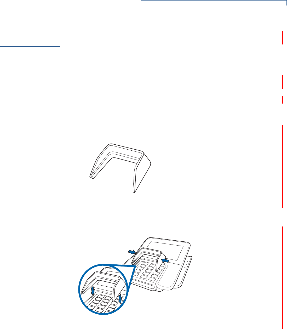
Privacy Shield
The privacy shield is used to hide the keys while the cardholder enters a PIN
during a transaction.
Figure 20 M400 Privacy Shield
Installing the Privacy
Shield To install a privacy shield:
1Squeeze in sides to slide in hooks into the slot.
Figure 21 Installing the Privacy Shield
SETUP
Optional Accessories
28 M400 INSTALLATION GUIDE
2Release to lock-in hooks in place.
Figure 22 Privacy Shield attached to Terminal
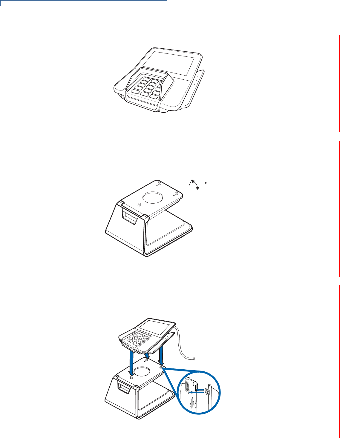
Stand
A mounting device that serves as the terminal’s docking station and adds support
during customer pin entry. The stand can be positioned on a countertop and can
be adjusted during transactions for convenience.
Figure 23 M400 Series Stand
Docking the Terminal
on the Stand To dock the terminal on the stand:
1Place the terminal on the base. Ensure that the stand screws align with the
keyholes found at the back of the terminal.
Figure 24 Docking Terminal onto the Stand
45
SETUP
Optional Accessories
M400 INSTALLATION GUIDE 29
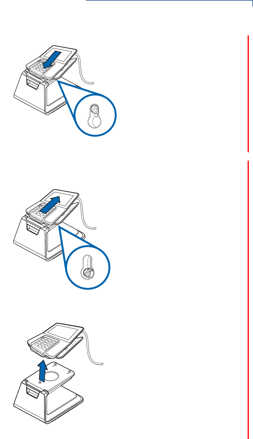
2Slide down terminal to lock in place.
Figure 25 Locking Terminal in Place
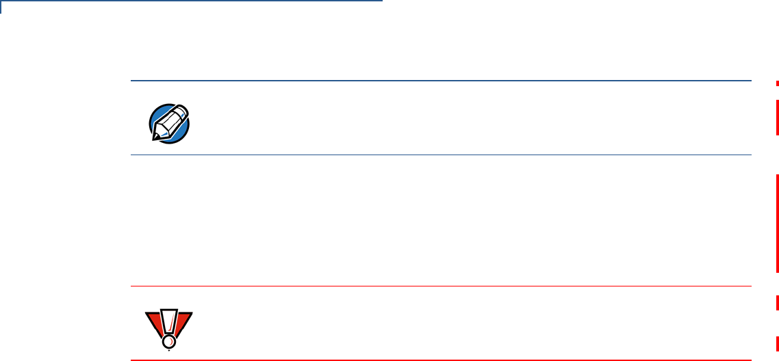
Undocking the
Terminal from the
Stand
To undock the terminal from the stand:
1Slide off terminal upward to unhook the terminal from the stand.
Figure 26 Undocking Terminal from the Stand
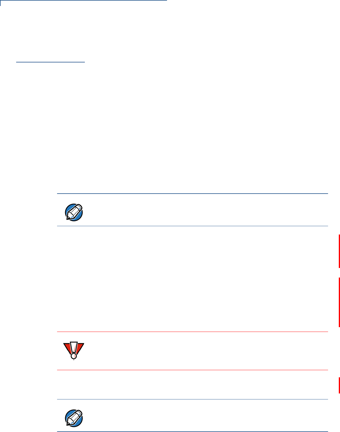
2Lift terminal off the stand.
Figure 27 Lifting Terminal off the Stand
SETUP
Optional Accessories
30 M400 INSTALLATION GUIDE
External and
Optional Devices
The ICE Cube, while connected to a terminal, supports peripheral devices
designed for use with electronic point-of-sale system such as ECR, cash drawer,
barcode scanner, external keyboard, weighing scale, external printer, external
speakers, and PINpad through a serial or USB Host connection. See Figure 7 for
reference.
NOTE
When conducting customer transactions, you can remove the terminal or adjust
the stand orientation for convenience.
CAUTION
Remove the power cord from the base module before connecting any peripheral
device. Reconnect the power cord only after you have finished connecting the
peripheral device(s).

M400 INSTALLATION GUIDE 31
CHAPTER 3
Specifications
This chapter discusses power requirements, dimensions, and other specifications
of the terminal.
Power Rating
•12 V DC, 1 A
Power Pack
•PWR445-001-01-A
•UL/cUL, ITE listed, LPS power supply
•Input rated: 100-240 V AC, 50/60 Hz
•Output rated: 12 V DC, 1 A, 12 W
Temperature
•Operating temperature: -5° to 50° C (23° to 122° F)
•Storage temperature: -20° to 60° C (-4° to 140° F)
External
Dimensions
•Length: 173 mm (6.81 in.)
•Width: 175 mm (6.89 in.)
•Depth: 43 mm (1.69 in.)
Weight
•Unit weight: 430 g
Processor
•1 GHz ARM Cortex A9
Memory
•256 MB of flash memory and 512 MB SDRAM
Display
•5” IPS LCD
Magnetic Card
Reader
•Triple track (tracks 1, 2, 3), high coercivity, bi-directional
Primary Smart
Card
•ISO 7816, 1.8 V, 3 V, 5 V
•Synchronous and asynchronous cards

SPECIFICATIONS
SAM Card Reader
32 M400 INSTALLATION GUIDE
SAM Card
Reader
The terminal has two dual stacking Security Access Modules (SAMs) card slots.
SD Card Reader
The terminal has one Micro Secure Digital (SD) card slot.
Integrated
Contactless
Reader
ISO 14443, ISO 18092, EMV, FeliCa
Keypad
•12-key Telco-style keypad
•Three color-coded function keys below the keypad
•Keys can be simulated on touchscreen
Audio Jack
3.5 mm headphone jack
Peripheral Ports
•one USB Type C port for ICE Cube Base module connection.
•one Micro-USB port for a graphometric stylus connection.
Security
Complies to PCI 4.x requirements, as well as many regional security
requirements.

M400 INSTALLATION GUIDE 33
CHAPTER 4
Maintenance and Cleaning
Your terminal device is a product of superior design and craftsmanship and should
be treated with care. It has no user-serviceable parts. The following suggestions
will help you protect your warranty coverage.
•Keep the device dry. Precipitation, humidity, and all types of liquids or moisture
can contain minerals that will corrode electronic circuits. If your device does
get wet, switch off the power, and allow the device to dry completely before
replacing it.
•Do not use or store the device in dusty and dirty areas. Its moving parts and
electronic components can be damaged.
•Do not store the device in hot areas. High temperatures can shorten the life of
electronic devices, damage batteries, and warp or melt certain plastics.
•Do not store the device in cold areas. Moisture can form inside the device and
damage electronic circuit boards when the device returns to its normal
temperature.
•Do not drop, knock, or shake the device. Rough handling can break internal
circuit boards and fine mechanics.
•Do not use harsh chemicals, cleaning solvents, or strong detergents to clean
the device. Use only a soft, clean, and dry cloth for cleaning.
•Do not paint the device. Paint can clog the moving parts and prevent proper
operation.
•Keep the device free from any small and loose items (such as paper clips,
staples, or coins) that could accidentally get inside it through an opening, such
as the SD card reader slot or the primary smart card reader slot.
•Do not attempt to open the device other than as instructed in this guide. This
device has security features that protect it from tampering. For example, the
file content will be deleted if the device’s outer casing is opened.
These suggestions apply equally to your terminal device, or any of its attachments
or accessories. If your device is not working properly, take it to the nearest
authorized service facility for servicing or replacement. For your safety, have this
device serviced only by a Verifone-authorized service provider.
CAUTION
Never use thinner, trichloroethylene, or ketone-based solvents – they can
deteriorate plastic or rubber parts. Do not spray cleaners or other solutions
directly onto the keypad or display.
MAINTENANCE AND CLEANING
Additional Safety Information
34 M400 INSTALLATION GUIDE
Additional
Safety
Information
The following are additional safety information in using this device.
Power Adapter
Use only the power adapter that came with your device. Adapters for other
electronic devices may look similar, but they may affect your device’s performance
or damage it.
Potentially
Explosive
Environments
Do not use this device in any area with a potentially explosive atmosphere. Follow
all signs and instructions. Potentially explosive atmospheres include areas where
you would normally be advised to turn off your vehicle engine. Sparks in such
areas could cause an explosion or fire resulting in bodily injury or even death.
Magnetic Stripe
Cleaner
The Magnetic Stripe Reader (MSR) must be cleaned on a regular basis (daily to
once a week, depending on usage), as dirt accumulation can lead to MSR reading
problems. MSR can be cleaned using commercially available card reader
cleaning cards, or using recommended Verifone cleaning card (PN 02746-02).
Smart Card Cleaner
The Smart Card Reader (SCR) must be cleaned on a regular basis, as dirt
accumulation can lead to SCR reading problems. SCR can be cleaned using
commercially available card reader cleaning cards, or using recommended
Verifone cleaning card (PN 02746-02).
Cleaning the SCR To clean the SCR:
1Inspect the terminal’s SCR for presence of foreign objects before cleaning
Customer Smart Card.
aIf unit shows no presence of foreign objects, test the SCR function and
record results. Proceed to Step 2.
2Clean the SCR with approved or recommended Verifone cleaning card. It is
advised to use new cleaning cards at all times.
NOTE If using a commercially available cleaning card use ONLY an approved MSR
cleaning card made specifically for POS MSR Card reader terminals or
Petroleum MSR card readers.
CAUTION Send your terminal to a Verifone authorized repair center if foreign objects
are found in the SCR at any time during SCR inspection, test diagnostics,
or cleaning process. Removal of foreign objects from the SCR by customers may
void terminal warranty.
NOTE If using a commercially available cleaning card use ONLY an approved SCR
cleaning card made specifically for POS SCR terminals or Petroleum SCR.

M400 INSTALLATION GUIDE 35
3Test the SCR after cleaning.
aIf SCR tests out okay as “passing”, then the unit is ready for Customer
Smart Card use.
bIf SCR tests out as “failing”, then send the unit for repair. Provide details to
repair center when SCR failed testing, either before cleaning OR after
cleaning OR both before and after cleaning.

MAINTENANCE AND CLEANING
Additional Safety Information
36 M400 INSTALLATION GUIDE
M400 INSTALLATION GUIDE 37
CHAPTER 5
Service and Support
Contact your local Verifone representative or service provider for any problems on
your terminal.
For product service and repair information:
•USA – Verifone Service and Support Group, 1-800-834-4366,
Monday - Friday, 8 A.M. - 8 P.M., Eastern time.
•International – Contact your Verifone representative.
Service Returns
You must obtain a Merchandise Return Authorization (MRA) number before
returning the terminal to Verifone. The following procedure describes how to
return one or more terminals for repair or replacement (U.S. customers only).
Returning One or
More Terminals for
Repair or
Replacement
1Gather the following information from the printed labels on the bottom of each
terminal to be returned:
•Product ID, including the model and part number. For example, “M400”,
“m445-xxx-xx”, and “PTID xxxxxxxx.”
•Serial number (S/N xxx-xxx-xxx).
2Obtain the MRA numbers by completing the following:
•Call Verifone within the United States toll-free at 1-800-Verifone and follow
the automated menu options.
•Select the MRA option from the automated message. The MRA
department is open Monday–Friday, 8 A.M.–8 P.M., Eastern time.
•Give the MRA representative the information gathered in Step 1.
If the list of serial numbers is long, you can fax the list, along with the
information gathered in Step 1, to the MRA department at 1-727-953-
4172 (U.S.).
•Address the fax clearly to the attention of the “Verifone MRA Dept.” Include
a telephone number where you can be reached and your fax number.
•Complete the Inquiry Contact Form at http://www.verifone.com/aboutus/
contact/contact_form.cfm.
•Address the Subject box with to “Verifone MRA Dept.”
NOTE
For international customers, please contact your local Verifone representative for
assistance with your service, return, or replacement.

SERVICE AND SUPPORT
Accessories and Documentation
38 M400 INSTALLATION GUIDE
•Reference the model and part number in the Note box
3Describe the problem(s).
4Provide the shipping address where the repaired or replacement unit must be
returned.
5Keep a record of the following items:
•Assigned MRA number(s).
•Verifone serial number assigned to the terminal you are returning for
service or repair (serial numbers are located on the bottom of the unit).
•Shipping documentation, such as air bill numbers used to trace the
shipment.
•Model(s) returned (model numbers are located on the Verifone label on the
bottom of the terminal).
Accessories and
Documentation
Verifone produces accessories and documentation for the terminal. Refer to the
part number in the left column when ordering.
Verifone Online Store at www.store.verifone.com
•USA – Verifone Customer Development Center, 1-800-834-4366,
Monday - Friday, 7 A.M. - 8 P.M., Eastern time
•International – Contact your Verifone representative
Below are accessories used with your terminal. Contact your Verifone distributor
to determine which of the accessories fit your requirements.
NOTE
One MRA number must be issued for each terminal you return to Verifone, even
if you are returning several of the same model.
Table 1 Accessories and VPNs
Accessory Part Number Description
Power pack PWR445-001-01-A M400 DC power pack
Verifone cleaning Kit VPN 02746-01 Cleaning kit
Privacy Shield PPL445-013-01-A PCI Privacy Shield
Stand TBD Multilane Stand
Stylus STY445-001-01-A Passive Stylus
Holster PPL445-008-01-A Stylus Holster
Berg Adaptor 445-100-01-A Berg Adaptor Cable
Base Module 445-101-01-A ICE Cube Base Module
Serial (COM) Interface
Module
445-102-01-A RS-232 Serial Interface
USB Interface Module 445-103-01-A USB Interface
Ethernet Interface Module 445-104-01-A Ethernet Interface Module

SERVICE AND SUPPORT
Accessories and Documentation
M400 INSTALLATION GUIDE 39
Refer to the following set of documents to learn more about the terminal:
Ethernet Switch Interface
Module
445-105-01-A Ethernet Switch Interface
Module
Tailgate Interface Module 445-106-01-A Tailgate Interface Module
USB CBL445-002-00-A Base Module + USB Module
2 USB Ports CBL445-003-00-A Base Module + USB Module
+ USB Module
Serial CBL445-004-00-A Base Module + Serial Module
2x Serial with Tailgate CBL445-005-00-A Base Module + Serial Module
+ Tailgate Module
Ethernet CBL445-006-00-A Base Module + Ethernet
Module
Ethernet with USB CBL445-007-00-A Base Module + Ethernet
Module + USB Module
Ethernet with Serial (COM2) CBL445-008-00-A Base Module + Ethernet
Module + Serial Module
Ethernet with Tailgate CBL445-009-00-A Base Module + Ethernet
Module + Tailgate Module
Ethernet Switch CBL445-010-00-A Base Module + Ethernet
Switch Module
Ethernet Switch with Tailgate CBL445-011-00-A Base Module + Ethernet
Switch Module+ Tailgate
M400 Certifications and Regulations VPN - DOC445-001-EN
M400 Series Quick Installation Guide VPN - DOC445-002-EN
M400 Series Ice Cube Certifications and Regulations VPN - DOC445-005-EN
M400 Series Ice Cube Quick Installation Guide VPN - DOC445-006-EN
M400 Series Stand Quick Installation Guide VPN - DOC445-007-EN
M400 Series Privacy Shield Quick Installation Guide VPN - DOC445-008-EN
VOS Programmers Manual VPN - DOC00501
Table 1 Accessories and VPNs
Accessory Part Number Description

SERVICE AND SUPPORT
Accessories and Documentation
40 M400 INSTALLATION GUIDE
M400 INSTALLATION GUIDE 41
CHAPTER 6
Troubleshooting
Guidelines
This chapter lists typical examples of malfunctions that you may encounter while
operating your terminal and the steps that you can take to resolve them.
The troubleshooting guidelines provided in the following sections are included to
assist successful installation and configuration of the terminal. Please read these
troubleshooting examples if you are having problems operating your unit. Contact
your local Verifone representative for assistance if the problem persists even after
performing the outlined guidelines or if the problem is not described.
Terminal Does
Not Start
If the terminal does not start:
•Ensure that the terminal is plugged into a dedicated power source.
•Check power cable connector is plugged in properly.
Terminal Display
Does Not Show
Correct/
Readable Info
If the terminal display does not show correct/readable info:
•Check all cable connections. If the problem persists, contact your local
Verifone representative for assistance.
NOTE
The terminal comes equipped with tamper-evident labels. It contains no user-
serviceable parts. Do not, under any circumstance, attempt to disassemble the
unit. Perform only those adjustments or repairs specified in this guide. Contact
your local Verifone service provider for all other services. Service conducted by
parties other than authorized Verifone representatives may void any warranty.
CAUTION
All units require use of a power supply.
Use only a Verifone-supplied power pack. Using an incorrectly rated power
supply may damage the unit or cause it not to work properly. Ensure that the
power supply used to power the unit matches the requirements specified on the
back of the unit (see Specifications for detailed power supply specifications)
before troubleshooting. If not, obtain the appropriately rated power supply before
continuing with troubleshooting.

TROUBLESHOOTING GUIDELINES
Blank Display
42 M400 INSTALLATION GUIDE
Blank Display
When the terminal display is blank:
•If the terminal display is dark, tap the screen with the stylus or your finger. If
the unit was in screen-saver mode, the screen will turn on when touched.
•If the display does not show correct or readable information, check all cable
connections. If the problem persists, contact your local Verifone representative
for assistance.
Keypad Does
Not Respond
If the keypad does not respond properly:
•Check the terminal display. If it displays the wrong character or nothing at all
when you press a key, follow the steps outlined in Transactions Fail To
Process.
•Refer to the user documentation for that application if pressing a function key
does not perform the expected action to ensure you are entering data
correctly.
•Contact your local Verifone representative if the problem persists.
Transactions
Fail To Process
There are several possible reasons why the unit may not be processing
transactions. Use the following steps to troubleshoot failures.
Checking Magnetic
Card Reader To check magnetic card reader:
1Perform a test transaction using one or more different magnetic stripe cards to
ensure the problem is not a defective card.
2Ensure that you are swiping cards properly (see Magnetic Card Reader).
3Process a transaction manually using the keypad instead of the card reader. If
the manual transaction works, the problem may be a defective card reader.
4Contact your local Verifone representative if the problem persists.
Checking Smart Card
Reader To check smart card reader:
1Perform a test transaction using several different smart cards to ensure the
problem is not a defective card.
2Ensure that the card is inserted correctly (see Smart Card Reader).
3Ensure the MSAM cards are properly inserted in the slots and are properly
secured (see MSAM Card).
4Contact your local Verifone representative if the problem persists.

TROUBLESHOOTING GUIDELINES
Transactions Fail To Process
M400 INSTALLATION GUIDE 43