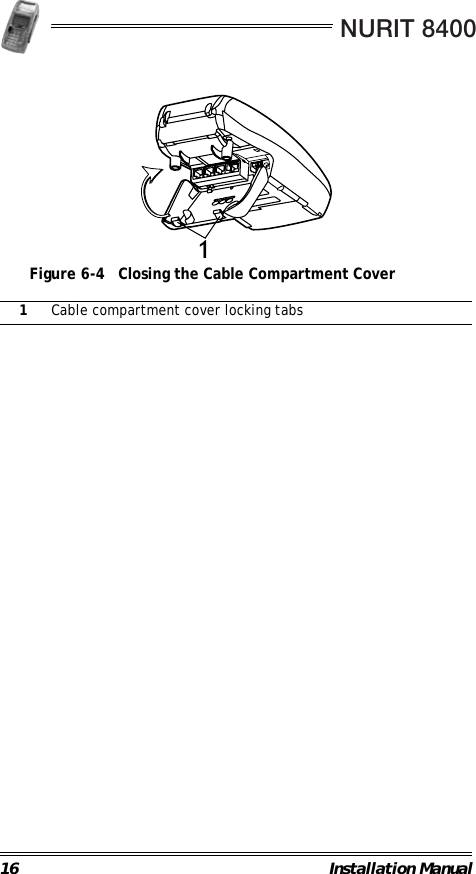
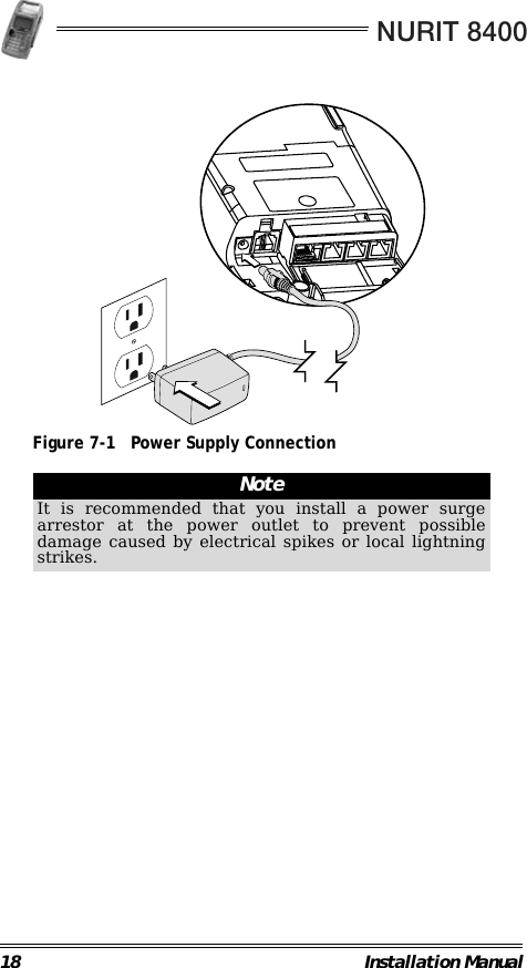
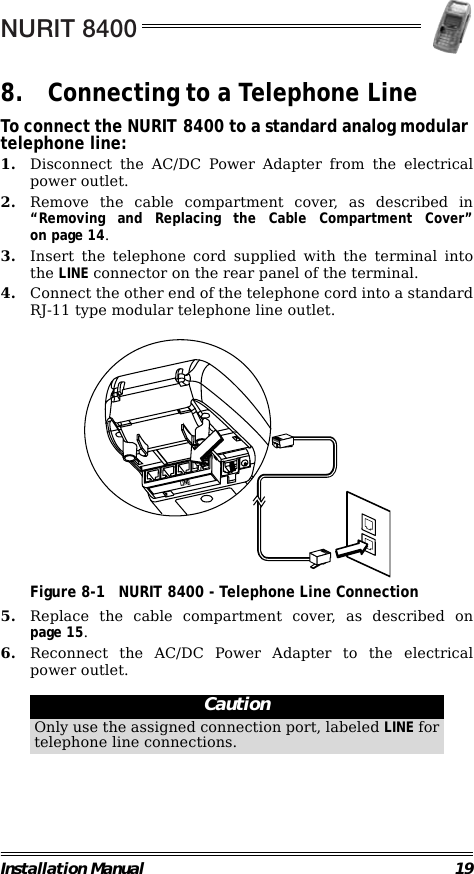
Verifone NURIT8400SSQ Countertop POS Terminal User Manual NURIT 8400 Installation Manual

VeriFone Inc Countertop POS Terminal NURIT 8400 Installation Manual

User Manual

NURIT 8400Countertop Payment TerminalInstallation Manual
Copyright2007 ©VeriFone, Inc.All rights reserved. No part of the contents of this documentmay be reproduced or transmitted in any form without thewritten permission of VeriFone, Inc.The information contained in this document is subject tochange without notice. Although VeriFone has attempted toensure the accuracy of the contents of this document, thisdocument may include errors or omissions. The examples arefor illustration only and may not be suited for your purpose.This document, including without limitation, the examples issupplied "As-Is."Trademark InformationVeriFone, the VeriFone logo, and NURIT are registeredtrademarks of VeriFone. Other brand names or trademarksassociated with VeriFone's products and services aretrademarks of VeriFone, Inc.All other brand names and trademarks appearing in this manualare the property of their respective holders.Catalog NumberDOC108EN01-BPrint DateOctober 2007
NURIT 8400Installation Manual iiiForewordThank you for purchasing the NURIT 8400Countertop Payment Terminal. You now own one of the mostadvanced, versatile, secure, and convenient POS terminalsmanufactured today.This manual provides basic installation instructions. To fullyutilize the features of your NURIT 8400, and for general safetypurposes, it is recommended that you familiarize yourself withthis manual, the terminal and any peripheral equipment oraccessories.                                                        It is recommended that you store this manual in a safe place forfuture reference.Document Conventions                                                        NoteAll graphic images in this manual are for illustrativepurposes only. Different models of this terminal mayexist and may vary in appearance according to countryof use or particular customer requirements.Although operation of the terminal may beapplication-dependent, basic installation proceduresare the same for most models.Warning Failure to follow specific procedures and practicesmay result in personal injuryCaution Failure to follow specific procedures and practicesmay result in damage to the NURIT device or otherequipmentNote Helpful hints and other important information aboutthe use of the NURIT device
NURIT 8400Installation Manual vTable of ContentsForeword  . . . . . . . . . . . . . . . . . . . . . . . . . . . . . iiiDocument Conventions . . . . . . . . . . . . . . . . . . . . . . . . iii1. Product Regulatory Information. . . . . . . . . . . . . . . .12. General Safety Instructions  . . . . . . . . . . . . . . . . . .3Radio Frequency Energy Emission . . . . . . . . . . . . . . . . .  4Safety Precautions for Medical Devices  . . . . . . . . . . . . .  5Pacemakers  . . . . . . . . . . . . . . . . . . . . . . . . . . . . . . .  53. Specifications  . . . . . . . . . . . . . . . . . . . . . . . . . . .64. Initial Setup  . . . . . . . . . . . . . . . . . . . . . . . . . . . .7Contents Checklist . . . . . . . . . . . . . . . . . . . . . . . . . . .  8Selecting a Point-of-Sale Location. . . . . . . . . . . . . . . . .  85. General Features . . . . . . . . . . . . . . . . . . . . . . . . 116. Removing and Replacing the CableCompartment Cover . . . . . . . . . . . . . . . . . . . . . . 147. Connecting to the Power Supply . . . . . . . . . . . . . .178. Connecting to a Telephone Line  . . . . . . . . . . . . . . 19Telephone Outlet Types. . . . . . . . . . . . . . . . . . . . . . . .209. Connecting an External Telephone. . . . . . . . . . . . . 2110. Connecting to a LAN . . . . . . . . . . . . . . . . . . . . . . 2211. Connecting an External PIN Pad  . . . . . . . . . . . . . . 2412. Connecting Peripheral Devices  . . . . . . . . . . . . . . . 2513. Loading Paper in the Printer. . . . . . . . . . . . . . . . .28Removing the Paper Roll from the Printer. . . . . . . . . . . .3014. Installing and Removing the Keypad Privacy Shield . . 3115. Removing and Replacing the Battery/SAM-SD/MMC Compartment Cover . . . . . . . . . . . . . . . . . . . . . . 3316. Installing and Removing the Battery. . . . . . . . . . . . 35Battery Maintenance  . . . . . . . . . . . . . . . . . . . . . . . . .36
NURIT 8400vi Installation Manual17. Installing SIM, SAM, and SD/MMC Cards. . . . . . . . . . 38Installing and Removing the SAM-SD/MMC Adapter . . . . .  38SAM and SD/MMC Card Configurations  . . . . . . . . . . . . .  40Installing a SAM Card. . . . . . . . . . . . . . . . . . . . . . . . .  40Installing an SD/MMC Card . . . . . . . . . . . . . . . . . . . . .  42Installing a SIM card . . . . . . . . . . . . . . . . . . . . . . . . .  4318. General Care and Maintenance . . . . . . . . . . . . . . .45Maintenance Recommendations  . . . . . . . . . . . . . . . . .  45Cleaning the NURIT 8400 . . . . . . . . . . . . . . . . . . . . . .  45Shipping the NURIT 8400 . . . . . . . . . . . . . . . . . . . . . .  46Technical Assistance . . . . . . . . . . . . . . . . . . . . . . . . .  4619. Troubleshooting . . . . . . . . . . . . . . . . . . . . . . . . . 47Appendix A: Using the Magnetic Stripe Card Reader . 49Appendix B: Using the Smart Card Reader. . . . . . . . 50Installation Notes . . . . . . . . . . . . . . . . . . . . . . . .51Contact Information . . . . . . . . . . . . . . . . . . . . . .52
NURIT 8400Installation Manual viiList of FiguresFigure 4-1 Secure Device Label . . . . . . . . . . . . . . . . . . . . .  7Figure 4-2 NURIT 8400 - Box Contents. . . . . . . . . . . . . . . . .  8Figure 5-1 NURIT 8400 - Top View . . . . . . . . . . . . . . . . . . .12Figure 5-2 NURIT 8400 - Bottom View . . . . . . . . . . . . . . . . .13Figure 6-1 Opening the Cover Locking Tabs . . . . . . . . . . . . .14Figure 6-2 Lifting the Cable Compartment Cover  . . . . . . . . .14Figure 6-3 Positioning the Cable Compartment Cover  . . . . . .15Figure 6-4 Closing the Cable Compartment Cover . . . . . . . . .16Figure 7-1 Power Supply Connection. . . . . . . . . . . . . . . . . .18Figure 8-1 NURIT 8400 - Telephone Line Connection . . . . . . .19Figure 9-1 External Telephone Connection  . . . . . . . . . . . . .21Figure 10-1 Typical Ethernet/RS-485 LAN Connection . . . . . . .22Figure 11-1 PIN Pad Connection  . . . . . . . . . . . . . . . . . . . . .24Figure 12-1 Peripheral Device Connection. . . . . . . . . . . . . . .26Figure 12-2 Typical Connection to an ECR. . . . . . . . . . . . . . .27Figure 12-3 Typical USB Connection to a PC-POS  . . . . . . . . . .27Figure 13-1 Opening the Paper Compartment  . . . . . . . . . . . .28Figure 13-2 Unrolling the Paper Roll  . . . . . . . . . . . . . . . . . .28Figure 13-3 Inserting a Paper Roll . . . . . . . . . . . . . . . . . . . .29Figure 13-4 Closing the Paper Compartment . . . . . . . . . . . . .29Figure 13-5 Removing the Paper Roll . . . . . . . . . . . . . . . . . .30Figure 14-1 Installing the Keypad Privacy Shield. . . . . . . . . . .31Figure 15-1 Removing the battery/SAM-SD/MMCCompartment Cover . . . . . . . . . . . . . . . . . . . . .33Figure 15-2 Replacing the battery/SAM-SD/MMCCompartment Cover . . . . . . . . . . . . . . . . . . . . .34Figure 16-1 Installing the Battery  . . . . . . . . . . . . . . . . . . . .35Figure 17-1 Installing the SAM-SD/MMC Adapter . . . . . . . . . . .39Figure 17-2 SAM and SD/MMC Cards Configurations. . . . . . . . .40Figure 17-3 SAM Cardholder Locking-Clasp  . . . . . . . . . . . . . .41Figure 17-4 SAM Card Installation  . . . . . . . . . . . . . . . . . . . .41Figure 17-5 SD/MMC Card. . . . . . . . . . . . . . . . . . . . . . . . . .42Figure 17-6 Lifting the SIM Card Cover . . . . . . . . . . . . . . . . .43Figure A-1 Using the Magnetic Stripe Card Reader. . . . . . . . .49Figure B-1 Using the Smart Card Reader . . . . . . . . . . . . . . .50
NURIT 8400Installation Manual 11. Product Regulatory Information                                                        FCC Compliance StatementManufacturer: VeriFone, Inc.Model: NURIT 8400FCC Part 15 RequirementsThis equipment has been tested and found to comply with thelimits for Class B digital device, pursuant to Part 15 of the FCCRules. These limits are designed to provide reasonableprotection against harmful interference when the equipment isinstalled and operated in a commercial environment.This equipment generates, uses and can radiate radiofrequency energy and, if not installed and used in accordancewith the instructions, may cause harmful interference to radiocommunications. However, there is no guarantee thatinterference will not occur in a particular installation.Operation of this equipment in a residential area is likely tocause harmful interference in which case the user will berequired to correct the interference at his/her own expense.If this equipment does cause harmful interference to radio ortelevision reception, which can be determined by turning theequipment off and on, the user is encouraged to try to correctthe interference by one or more of the following measures:• Reorient or relocate the receiving antenna.• Increase the separation between the equipment and thereceiver.• Connect the equipment into an outlet on a circuit differentfrom that to which the receiver is connected.• Consult your representative or an experienced technicianfor help.Connection of peripherals to this unit requires the use ofgrounded, shielded cables to ensure compliance with theClass B limits.CautionChanges or modifications to this device that are notexpressly approved by the party responsible forcompliance could void the user's authority to operatethe equipment.
NURIT 84002 Installation ManualIn CanadaThis digital apparatus does not exceed the Class B limits forradio noise emissions from digital apparatuses set forth in theRadio Interference Regulations of the Canadian Department ofCommunications.Cet appareil digital n'émet pas de bruits radioélectriquesdépassant les limites applicables aux appareils de la Classe B,déterminée par la Réglementation d'Interférence Radio duMinistère Canadien des Communications.EU Directives Compliance StatementThis product complies with the requirements of applicableEuropean Union Council Directives.                                                         NoteDisposal of this product or of any of its componentsmust be performed in full compliance with all EUand/or local directives and regulations. For moreinformation, contact your local VeriFonerepresentative or authorized VeriFone serviceprovider.
NURIT 8400Installation Manual 32. General Safety Instructions                                                        When using the NURIT 8400 or any associated device, thefollowing basic safety precautions should always be observed toreduce the risk of fire, electric shock, or personal injury:•Read and make sure you understand all instructions.•Follow all warnings and instructions marked on the deviceand in this manual.•Before cleaning, turn off the PC, ECR, or other device towhich the NURIT 8400 is connected and disconnect it fromelectrical power.•Do not use liquid or aerosol cleaners. Use a damp cloth forcleaning and/or a soft brush.•Never spill any liquid on the device.•Place the device in a stable position on a solid surface.Serious damage may result if the device falls.•Do not cover slots and openings of the device. They may beprovided for ventilation and protection against overheating.Never place the device near radiators, or in a place whereproper ventilation is not provided.•Do not place objects on the interconnection cables. Installthe device where no one can step on the cables.•Never push objects into the device through slots (other thanthose specifically intended for the SAM, SIM, SD/MMC,magnetic stripe, or smart cards.•To reduce the risk of electric shock, do not disassemble anyof the equipment or accessories referred to in this manual.If required, take the equipment to a qualified servicerepresentative. Incorrect reassembly or opening orremoving covers may expose you to dangerous voltages orother risks.NoteThese safety instructions are based on those providedby Underwriters Laboratories (UL) Inc. U.S.A.
NURIT 84004 Installation Manual                                                        Radio Frequency Energy EmissionYour NURIT 8400 may contain a transmitter and receiver thatemit radio frequency (RF) energy. The actual frequency rangeused by the NURIT 8400 is radio-modem dependent accordingto the specific model. Digital modulation techniques are used.During radio communication, the local radio system handlingthe actual communication controls the actual powertransmission output level. This output level may typically vary(relative to the distance between the user location and the celltransmission sites).RF energy may affect some electronic systems. Consult thespecific device manufacturer (or airline crew for possibleairborne operation) regarding permission to use this devicewhile airborne and associated problems. It is currently knownthat all radio-type devices are prohibited while airborne.•When used properly, the design of this handheld wirelessterminal complies with U.S., Canadian, European, and otherstandards for protection from public exposure to RFmagnetic signals.•This device has been tested and meets RF exposureguidelines for hand held operation pursuant to FCC OETBulletin 65 Syoolement C ed. 01-01, IEEE 1528/D1.2 (2003)and Industry Canada RSS-102 (1999).                                                        Warning•Do not use your NURIT 8400 in an area ofpotential explosive atmosphere, such as fuel orchemical storage or transfer facilities, or in anyarea where you would be advised to turn off avehicle's engine.•Do not use the NURIT 8400 in a known blastingarea.WarningThe NURIT 8400 must be located at least 20 cm(7.9 in) from all persons, and must not be co-located oroperated in conjunction with any other antenna ortransmitter.
NURIT 8400Installation Manual 5Safety Precautions for Medical DevicesFor persons using a pacemaker or other medical device, pleaseread the following important safety notes:•Though most electronic equipment and critical medicaldevices are shielded against radio-frequency signals, it isimportant to realize the possibilities of potentialinterference and to know the standard precautions thatmay be taken.•Consult the manufacturer of your medical device todetermine its level of shielding. Depending on the proximityto certain equipment, you may be asked not to use yourNURIT terminal or one of its accessories.PacemakersIndustry standards recommend a minimum separation of 15 cm(6 in) between a wireless phone-type device and a pacemaker toprevent any potential problems.Individuals using a pacemaker should:•Always keep the NURIT 8400 terminal more than 15 cm(6 in) from the pacemaker when using the unit for cellularwireless communication or when performing an onlinetransaction.•Turn off the NURIT 8400 terminal immediately anddisconnect if from the power supply if you suspect anyproblem of interference.
NURIT 84006 Installation Manual3. Specifications                                                                                                                Specification DetailsPower•Terminal 9 V at 4 A•AC/DC Adapter (Safety Approved)Input: 90-264 and 300 VACOutput: 9 VDC at 4 A3.3 V switching regulator•The AC/DC Adapter must be approved bythe relevant authorities in the countrywhere the equipment is sold.Dimensions•Height: 80.7 mm (3.2 in)Including the keypad privacy shield•Width: 109.9 mm (4.3 in)•Depth: 232.5 mm (9.2 in)Weight (approximate)•POS terminal: 600 g (21.16 oz)•Shipping weight may vary according tooptional accessories, documentation, andpackagingEnvironmental Requirements•Operating temperature:0° C to +50° C (+32° F to +122° F)•Storage temperature:-20° C to +60° C (-4° F to +140° F)•Relative humidity:5%-95% non-condensingModem Communication RateChoice of three speeds:•14.4 Kbps•56 Kbps•56 Kbps and V.92Note: Modem speed is model-dependentNoteSpecifications are subject to change without noticedue to changes to the device and its components.The above specifications may differ between models ofthe NURIT 8400.
NURIT 8400Installation Manual 74. Initial Setup                                                                                                     Figure 4-1 Secure Device Label                                                                                                                CautionThe box of a secure NURIT device should be sealedwith a Secure Device label. If the Secure Device labelon the box was damaged or missing, this could be anindication of device tampering and may affect thevalidity of the warranty for the device. Notify yourVeriFone service provider.NoteThe size, appearance and precise wording of theSecure Device label may vary according to theparticular service provider of the device.Caution•Carefully inspect the contents of the box for anydamaged or missing components. Do not use aNURIT device that shows any signs of damage.•VeriFone has taken all measures to provide youwith a complete device. If shipping damage isevident, file a claim with the shipping company.Notify your VeriFone service provider concerningthis damage, and if any components are missing.
NURIT 84008 Installation ManualContents Checklist                                             Figure 4-2 NURIT 8400 - Box Contents                                                                                                                Selecting a Point-of-Sale LocationThe NURIT 8400 is designed to be operated in the followinglocations:•Indoors, using the AC/DC Power Adapter.•Outdoors, powered only by a VeriFone-supplied or approvedbattery.1NURIT 8400 2Keypad privacy shield3AC-DC power adapter 4Battery (model-dependent)5SAM-SD/MMC Adapter(model-dependent) 6Documentation pack7Paper rollNote•Box contents may vary according to the specificmodel.•Some or all of the accessories contained in the boxmay already be installed in the terminal.•The contents of the documentation pack may varyaccording to customer requirements.3145267
NURIT 8400Installation Manual 9                                                                                                                •When not operated from its hand-held position, place theNURIT 8400 on a flat table or countertop close to a poweroutlet and any peripherals.•Maintain good ventilation around the terminal. Provide forat least 22 cm (8.5 in) of clear space around the terminal inits fixed operating location.•Do not cover the terminal.                                                                                                                WarningDo not locate the POS terminal where it can exposedto the following:•Devices that radiate excessive electrical noise orvoltage fluctuations, such as air conditioners, fans,electric motors, neon signs, or high-frequencysecurity devices.•Water containers, such as a sink, a laundry tub ora pool.•Areas of excessive moisture, heat, oil, dust ordebris.•Direct sunlight or objects that radiate heat.•Metal partitions or such obstructions that maydisrupt radio transmission or reception if yourterminal is used as a wireless device.CautionThe NURIT 8400 should not be powered or chargedoutdoors using its AC/DC adapter.CautionSome NURIT 8400 may have an optional internal radioinstalled. If you are operating a terminal with thisfeature, do not operate on a metal plate or nearmetallic objects.NoteBefore using the NURIT 8400, remove the transparentplastic membrane that covers the LCD screen.
NURIT 840010 Installation Manual                                                                                                                                                                        NoteTo ensure compliance of the NURIT 8400 as a securePIN entry device:•The customer should be able to obstruct visualobservation of the PIN entry with his/her body andhand.•The cardholder must be clearly instructed toobstruct visual observation of the PIN entry withhis/her body and hand.Failure to comply with these conditions may renderthe terminal non-compliant with ISO 9564 for PINprotection and may violate card associationrequirements for PIN entry devices.For more information, contact your local VeriFonerepresentative or service provider.Caution•A keypad privacy shield is preinstalled on allmodels of the NURIT 8400. Do not attempt totamper or remove the privacy shield. Tamperingwith the privacy shield may damage the deviceand make it inoperable.•If for any reason, the keypad privacy shield needsto be replaced, contact a VeriFone servicerepresentative.NoteDo not use a NURIT 8400 that shows any sign ofdamage.
NURIT 8400Installation Manual 115. General Features                                                        Feature DescriptionLCD Display •Graphical LCD display•Black and white with backlight•128 x 64 pixels, 63 x 35 mmKeypad20 keys comprised of:•10-key telephone-style keypad•10 Function and special keysFour optional ATM-like keysSmart Card Reader •Integrated, front-entry, EMV-compliant,smart card readerMagnetic Stripe Card Reader •Integrated, bi-directional 3-track magneticstripe card readerKeypad Privacy Shield •Preinstalled privacy shieldSAM-SD/MMC Adapter•Up to four SAM cards (0, 2, 4)•Up to two SAM (0, 2) and one SD/MMC cardNote: Configuration is model-dependentSIM Slot •Slot for the insertion of a SIM cardNote: SIM card is model-dependentThermal Printer •Integrated printer uses thermal paper•Easy-load mechanismConnectors•PWR (Power) Connector•COM1 and COM2 RS-232 Connectors (COM2is model dependent)•TEL Connector (RJ-11)•LINE Connector (RJ-11)•PIN (PIN pad) Connector•ENET, 10BaseT Ethernet LAN via EthernetConnector•RS-485 LAN•USB Host Connector (“A” Plug)•USB Device Connector (“mini-B” Plug)Note: Configuration is model-dependent
NURIT 840012 Installation Manual                                             Figure 5-1 NURIT 8400 - Top View                                                                                                                                 Battery•Two cell Lithium-ion (Li-Ion) battery•Supplies 7.4 V at 2200 mAH (minimum)•Fully recharges within six hours •Smart monitor communication•Charger includedNote: Battery is model-dependentRadio•Internal antennaChoice of:•GSM/GPRS•CDMANote: Radio is model-dependentModem Choice of three speeds (model-dependent).1Paper cover  2Magnetic stripe card slot 3ATM-like keys(model-dependent) 4LCD display5Keypad privacy shield 6Keypad7Smart card slotFeature Description5671324
NURIT 8400Installation Manual 13                                             Figure 5-2 NURIT 8400 - Bottom View                                                        1Cable compartment cover 2Battery/SAM-SD/MMCcompartment3Rubber stop 4Compliance label5Model/serial number label12345
NURIT 840014 Installation Manual6. Removing and Replacing the CableCompartment CoverThe cable connection panel on the NURIT 8400 is located onthe bottom of the base unit, behind a cover for the cables. Thecables cover must be removed before you can connect theterminal to the power supply, telephone line, or peripheraldevices.To remove the cable compartment cover:1. Carefully hold the NURIT 8400 face down or place it on asoft, smooth surface, so as not to damage the LCD display.2. Steady the unit with one hand, with the bottom of theterminal facing you.3. On the cable compartment cover, place a finger in thegroove of each of the two locking tabs.                                             Figure 6-1 Opening the Cover Locking Tabs4. Pull and lift the cover, exposing the terminal connectors.5. Remove the connectors cover.                                             Figure 6-2 Lifting the Cable Compartment Cover
NURIT 8400Installation Manual 15To replace the cable compartment cover:1. Hold the cover at a 40° angle, with the hinge tabs facingdown.2. Insert the hinge tabs into the tab slots, located above theconnectors.                                             Figure 6-3 Positioning the Cable Compartment Cover3. Lower the cover and press down until the locking tabs snapinto place.
NURIT 840016 Installation Manual                                             Figure 6-4 Closing the Cable Compartment Cover                                                        1Cable compartment cover locking tabs1
NURIT 8400Installation Manual 177. Connecting to the Power SupplyTo connect the NURIT 8400 to the power supply:1. Remove the cable compartment cover, as described in“Removing and Replacing the Cable Compartment Cover”on page 14.2. Connect the barrel plug on the AC/DC Power Adapter cableto the connector labeled PWR on the rear panel of theterminal.3. Connect the other end of the AC/DC Power Adapter cable toan electrical power outlet.4. Replace the cable compartment cover, as described onpage 15.                                                                                                                                                                        WarningUse only the VeriFone supplied AC/DC Power Adapterto power the NURIT 8400.WarningDo not plug the AC/DC Power Adapter into an outdoorelectrical power outlet.CautionDisconnecting the terminal from the power outlet willdisrupt the transaction process.
NURIT 840018 Installation Manual                                             Figure 7-1 Power Supply Connection                                                         NoteIt is recommended that you install a power surgearrestor at the power outlet to prevent possibledamage caused by electrical spikes or local lightningstrikes.
NURIT 8400Installation Manual 198. Connecting to a Telephone LineTo connect the NURIT 8400 to a standard analog modular telephone line:1. Disconnect the AC/DC Power Adapter from the electricalpower outlet.2. Remove the cable compartment cover, as described in“Removing and Replacing the Cable Compartment Cover”on page 14.3. Insert the telephone cord supplied with the terminal intothe LINE connector on the rear panel of the terminal.4. Connect the other end of the telephone cord into a standardRJ-11 type modular telephone line outlet.                                             Figure 8-1 NURIT 8400 - Telephone Line Connection5. Replace the cable compartment cover, as described onpage 15.6. Reconnect the AC/DC Power Adapter to the electricalpower outlet.                                                         CautionOnly use the assigned connection port, labeled LINE fortelephone line connections.LINE
NURIT 840020 Installation Manual                                                                                                                Telephone Outlet TypesThe following types of telephone outlets are common:•ModularThis is the most common type of telephone outlet used. Plugthe supplied telephone cord from the terminal into a stan-dard modular telephone connector. If you do not have amodular connector, contact your local telephone companyor a qualified telephone technician.•4-Prong ConnectorYou must purchase a special adapter for use with a 4-prongconnector. This adapter plugs into the 4-prong connectorand the telephone line cord plugs into the adapter.•Hard-wiredYou must purchase a special modular connector adapter forthis direct-type hard-wire connection that replaces olderconnecting blocks. Contact your local telephone companyor a qualified telephone technician for correct informationon color-coded connections.NoteIt is recommended that you use a dedicated telephoneline with the NURIT 8400. In some models the phoneline is disabled during transactionsNoteUse only the telephone cord shipped with the terminal.Using a different telephone cord may cause theterminal to malfunction.
NURIT 8400Installation Manual 219. Connecting an External TelephoneYou can connect a standard external telephone to a model of theNURIT 8400 that uses the analog telephone network forcommunications and does not support a LAN connection.To connect an external telephone to the NURIT 8400:1. Disconnect the AC/DC Power Adapter from the electricalpower outlet.2. Remove the cable compartment cover, as described in“Removing and Replacing the Cable Compartment Cover”on page 14.3. On the rear panel of the NURIT 8400, insert one end of atelephone cord (model dependent, VeriFone supplied) intothe TEL connector.4. Insert the other end of the telephone cord into the RJ-11type modular connector on the base of the telephone.                                             Figure 9-1 External Telephone Connection5. Replace the cable compartment cover, as described onpage 15.6. Reconnect the AC⁄DC Power Adapter to the electrical poweroutlet.                                                         NoteIf you want to connect an external telephone to theNURIT 8400 terminal, along with an analog telephonenetwork connection, you must use a 2-socket RJ-11plug in the modular wall connector.TEL
NURIT 840022 Installation Manual10. Connecting to a LANSome models of the NURIT 8400 can be connected to a LocalArea Network (LAN). Depending on the specific model, theNURIT 8400 can be connected to either an RS-485 LAN or a10BaseT Ethernet LAN.To connect the NURIT 8400 to an Ethernet LAN:1. Disconnect the AC/DC Power Adapter from the electricalpower outlet.2. Remove the cable compartment cover, as described in“Removing and Replacing the Cable Compartment Cover” onpage 14. 3. Connect the Ethernet Adapter cable to the ENET connectoron the connections panel.4. Connect the other end of the Ethernet Adapter cable to oneend of the network cable.5. Connect the other end of the network cable to a networkwall outlet, switch, or other compatible network device.                                             Figure 10-1 Typical Ethernet/RS-485 LAN Connection6. Replace the cable compartment cover, as described onpage 15.7. Reconnect the AC/DC Power Adapter to the electricalpower outlet.
NURIT 8400Installation Manual 23To connect the NURIT 8400 to an RS-485 LAN:1. Disconnect the AC/DC Power Adapter from the electricalpower outlet.2. Remove the cable compartment cover, as described in“Removing and Replacing the Cable Compartment Cover” onpage 14.3. Connect the network cable to the RS-485 connector on theconnections panel.4. Connect the other end of the network cable to a networkwall outlet, switch, or other compatible network device.5. Replace the cable compartment cover, as described onpage 15.6. Reconnect the AC/DC Power Adapter to the electricalpower outlet.
NURIT 840024 Installation Manual11. Connecting an External PIN Pad                                                        To connect an external PIN pad to the NURIT 8400:1. Disconnect the AC/DC Power Adapter from the electricalpower outlet.2. Remove the cable compartment cover, as described in“Removing and Replacing the Cable Compartment Cover” onpage 14.3. Connect one end of the connector cable (supplied with theterminal) to the PIN connector on the rear panel of theNURIT 8400. 4. Verify that the other end of the connector cable isconnected to the PIN pad.5. Replace the cable compartment cover, as described onpage 15.6. Reconnect the AC/DC Power Adapter to the electricalpower outlet.                                             Figure 11-1 PIN Pad ConnectionCautionOnly use the assigned connection port, labeled PIN forPIN pad connections.PIN
NURIT 8400Installation Manual 2512. Connecting Peripheral DevicesModels of the NURIT 8400 may include ports, allowingconnection of the terminal to external devices, such as:•RS-232 connector•USB connector                                                                                                                                                                                                                                                                                        Caution•Turn off the POS terminal, ECR, or PC wheneveryou connect or disconnect the NURIT 8400.•Do not disconnect the NURIT 8400 when the POSterminal, ECR, or PC is processing data.CautionYou can connect to up to four external peripheraldevices to the NURIT 8400. Consult with yourVeriFone service provider for information about theperipheral devices that you can connect to yourspecific model.NotePeripheral devices may require special adapter cablesfor their connection to the NURIT 8400. In addition,certain peripheral devices require an external powersupply.Refer to the product documentation of the specificperipheral devices, or contact your local VeriFonerepresentative or service provider for further details.NoteUSB peripheral support requires the installation of acorresponding driver.NoteThe COM1 port provides a power supply for peripheraldevices. The power supply is 6 VDC (minimum)-9 VDC(maximum) at 250 mA. This also applies to themodel-dependent COM2 port, when there is no PIN padconnection.
NURIT 840026 Installation ManualTo connect an RS-232 peripheral device to the NURIT 8400:1. Disconnect the AC/DC Power Adapter from the electricalpower outlet.2. Remove the cable compartment cover, as described in“Removing and Replacing the Cable Compartment Cover” onpage 14. 3. Connect a peripheral device to one end of its adapter cable.4. Connect the other end of the adapter cable to either theCOM1 or COM2  (model-dependent) connector on theconnections panel.5. Replace the cable connection cover, as described onpage 15.6. Reconnect the AC/DC Power Adapter to the electricalpower outlet.                                             Figure 12-1 Peripheral Device Connection                                                        1Signature capture device 2PC3Barcode reader 4Electronic scale5Check reader 6Contactless readerPWRCOM1COM2123456
NURIT 8400Installation Manual 27To connect a USB peripheral device to the NURIT 8400:1. Disconnect the AC/DC Power Adapter from the electricalpower outlet.2. Remove the cable connection cover, as described in“Removing and Replacing the Cable Compartment Cover” onpage 14.3. Insert the USB plug into the USB connector on theperipheral device.4. Insert the USB plug into the USB connector on theNURIT 8400 terminal.                                             Figure 12-2 Typical Connection to an ECR                                             Figure 12-3 Typical USB Connection to a PC-POS5. Replace the cable connection cover, as described onpage 15.6. Reconnect the AC/DC Power Adapter to the electricalpower outlet.DRAWERETHERNET DISPLAY EXT.KB BARCODELINEPHONEPC PORTPINPADPOWERCOM1 COM2RS-232USBUSBUSB
NURIT 840028 Installation Manual13. Loading Paper in the PrinterTo load a roll of thermal paper in the printer:1. Place the terminal on a flat, stable surface.2. Insert two fingers into the recess on the papercompartment cover, beneath the release latch.3. Pull the opening latch up until the cover unlocks.4. Lift the paper compartment cover until it is fully open.                                             Figure 13-1 Opening the Paper Compartment                                                        5. Remove the tape strip from a new paper roll.6. Unroll approximately 5 cm (2 in) of paper to facilitate theloading process.                                             Figure 13-2 Unrolling the Paper Roll1Opening the paper coverlatch 2Opening the papercompartment21
NURIT 8400Installation Manual 297. Hold the paper roll with the unrolled end on the underside.8. Lower the paper roll into the paper compartment.                                             Figure 13-3 Inserting a Paper Roll9. Pull the unrolled end of the paper approximately 2.5 cm(1 in) out of the paper compartment, ensuring that thepaper feeds from the underside of the roll.10. Make sure that the opening latch is down, in its originalposition.11. Close the paper compartment cover, pressing press downfirmly, until it snaps into place.                                             Figure 13-4 Closing the Paper Compartment
NURIT 840030 Installation ManualRemoving the Paper Roll from the PrinterTo remove an empty roll of thermal paper from the printer:1. Place the terminal on a flat, stable surface.2. Insert two fingers into the recess on the papercompartment cover, beneath the release latch.3. Pull the opening latch up until the cover unlocks.4. Lift the paper compartment cover until it is fully open, asillustrated in Figure 13-1 on page 28.5. Lift the paper roll out of the paper compartment.                                             Figure 13-5 Removing the Paper Roll
NURIT 8400Installation Manual 3114. Installing and Removing the Keypad Privacy Shield                                                                                                                To install the keypad privacy shield:1. Place the terminal on a flat, stable surface, or hold itsecurely in one hand.2. Hold the keypad privacy shield above the terminal.3. Tilt one side of the keypad privacy shield downward at anangle of approximately 30°.                                             Figure 14-1 Installing the Keypad Privacy ShieldNoteThe keypad privacy shield is included only with modelsof the NURIT 8400 that are designed for secure PINentry.NoteIn addition to the installation of the keypad privacyshield, the cardholder must be clearly instructed toobstruct visual observation of the PIN entry withhis/her body and hand. (See “Selecting a Point-of-SaleLocation” on page 8.)Failing to install or removing the keypad privacyshield, or failing to instruct the cardholder to obstructvisual observation of the PIN entry with his/her bodyand hand, may render the terminal non-compliant withISO 9564 for PIN protection and may violate cardassociation requirements for PIN entry devices.
NURIT 840032 Installation Manual4. Insert the curved tab on the back side of the keypad privacyshield into the circular opening positioned on either side ofthe terminal (on either side of the top of the keypad area).5. Push down on the same side’s front of the keypad privacyshield, until the front tab snaps into place.6. Position the second tab, at the front of the terminal, into thetab slot.7. Push down on the remaining corner of the keypad privacyshield, until it snaps into place.To remove the keypad privacy shield:1. Place the terminal on a flat, stable surface, or hold itsecurely in one hand.2. Grasp either side of the keypad privacy shield.3. Squeeze and pull on a diagonal one of the back side tabs ofthe privacy shield until the back side tab releases.4. Pull the keypad privacy shield away from the terminal.
NURIT 8400Installation Manual 3315. Removing and Replacing the Battery/SAM-SD/MMC Compartment CoverTo remove the battery/SAM-SD/MMC compartment cover:1. Disconnect the AC/DC Power Adapter from the electricalpower outlet.2. Carefully turn the NURIT 8400 face down or place it on asoft, smooth surface, so as not to damage the LCD display.3. Steady the unit with one hand.4. With your other hand, use your thumb to press in and liftthe compartment cover.5. Remove the battery/SAM-SD/MMC compartment cover.                                             Figure 15-1 Removing the battery/SAM-SD/MMCCompartment Cover
NURIT 840034 Installation ManualTo replace the battery/SAM-SD/MMC compartment cover:1. Insert the two hinge tabs of the battery/SAM-SD/MMCcompartment cover into the tab slots on the edge of thecompartment.                                             Figure 15-2 Replacing the battery/SAM-SD/MMCCompartment Cover                                                        2. Lower the compartment cover, using your thumb to press inthe locking tab.3. Press in the locking tab and push down the compartmentcover until the cover snaps into place.1Cover locking tab1
NURIT 8400Installation Manual 3516. Installing and Removing the BatteryTo install the battery:1. Remove the battery/SAM-SD/MMC compartment cover, asdescribed in “Removing and Replacing the Battery/SAM-SD/MMCCompartment Cover” on page 33.2. If necessary, remove the SAM-SD/MMC adapter, asdescribed in “Installing and Removing the SAM-SD/MMCAdapter” on page 38.3. Hold the battery at a 30° angle, with the battery powerplug, facind down, into the compartment, making sure thatthe side with the arrow pictogram is facing upward.4. Slide the two tabs on the front of the battery into the slotson the front wall of the battery compartment.5. Slide the battery forward and down, until it snaps intoplace.6. If necessary, install the SAM-SD/MMC adapter, as describedin  “Installing and Removing the SAM-SD/MMC Adapter”on page 38.7. Replace the battery/SAM-SD/MMC compartment cover, asillustrated in Figure 15-2 on page 34.                                             Figure 16-1 Installing the Battery
NURIT 840036 Installation ManualTo remove the battery from the NURIT 8400:1. Remove the battery/SAM-SD/MMC compartment cover, asdescribed in “Removing and Replacing the Battery/SAM-SD/MMCCompartment Cover” on page 33.2. If necessary, remove the SAM-SD/MMC adapter, asdescribed in “Installing and Removing the SAM-SD/MMCAdapter” on page 38.3. Slide the battery in the direction of the arrow, gentlydetaching it from its socket.4. Remove the battery.Battery Maintenance                                                        •The supplied high-performance, smart Lithium-Ion batteryprovides 7.2 V at 2200 mAH (minimum) capacity.•When fully discharged, the battery fully recharges withinsix hours while installed in the terminal.•The terminal can be connected to an AC/DC power supplyindefinitely without causing damage to the battery.•In typical use, the life span of the battery exceeds 500charge cycles, after which, operating time decreases slowly.•The battery has a self-discharge rate. It loses approximately1% of its charge per day when not in use. Replace thebattery when the charge capacity is too weak for normaloperation.•Remove the battery from the terminal if you do not intendto use your NURIT 8400 for an extended period of time.                                                                                                                CautionTake care when installing the battery. If installedincorrectly, it may explode. Use only a VeriFonesupplied battery.WarningDo not break open or damage the casing of the battery.WarningDo not dispose of the NURIT 8400 Li-Ion smart batteryin a fire. Li-Ion batteries must be recycled or disposedof properly. Do not dispose of Li-Ion batteries inmunicipal waste sites.
NURIT 8400Installation Manual 37                                                                                                                NoteExtreme temperatures degrade the batteryperformance.Battery Environmental Requirements:•Charge: 0°C to 45°C (32°F to 113°F)•Discharge: -30°C to 60°C (-22°F to 140°F)•Storage:  -20°C to 45°C (-4°F to 113°F)NoteTo power on a terminal from “OFF” state, while usinga battery, press the bottom left button of the keypad.
NURIT 840038 Installation Manual17. Installing SIM, SAM, and SD/MMC CardsDepending on the particular model, you can install a variety ofelectronic memory or processing cards in the NURIT 8400:•Up to four (4) SAM (Secure Access Module) cards can beinstalled in SAM cardholders (2, 4), located on theNURIT 8400’s SAM-SD/MMC adapter. SAM cards may beused to hold encryption keys, identify the terminal ormerchant to the host, process applications, or a variety ofother uses.•One (1) SD (Secure Digital) or MMC (Multi-Media Card)cards, alongside up to two (2) SAM cards (0, 2). SD andMMC cards hold data, such as price lists and offlinetransaction information, where supported by theapplication.With any of these options, you can install a SIM Card for yourwireless transactions.                                                        .                                                        Installing and Removing the SAM-SD/MMC AdapterBefore using a terminal with SAM and/or SD/MMC cards, theadapter must be installed.To install the SAM-SD/MMC adapter:1. Remove the battery/SAM-SD/MMC compartment cover, asdescribed in “Removing and Replacing the Battery/SAM-SD/MMCCompartment Cover” on page 33.2. If required, install the battery, as described in “Installing andRemoving the Battery” on page 35.CautionDo not store any foreign objects in thebattery/SAM-SD/MMC adapter compartment.CautionThe contacts on the SAM, SIM, SD/MMC, andcardholders can be easily damaged. Do not bend orscratch when installing or removing the cards.
NURIT 8400Installation Manual 393. Hold the SAM-SD/MMC adapter with the cardholdersfacing upwards, and connector towards the terminal socket.4. Hold the SAM-SD/MMC adapter on a 30° angle, so that thefront tabs, on both the right and left of the board are in thefront slots.5. Gently push the adapter down, resting it in the grooves onthe sides of the compartment.6. Slide the adapter forward, until the locking button locksinto place.7. Replace the battery/SAM-SD/MMC compartment cover, asillustrated in Figure 15-2 on page 34.                                             Figure 17-1 Installing the SAM-SD/MMC Adapter                                                        To remove the SAM-SD/MMC adapter:1. Remove the battery/SAM-SD/MMC compartment cover, asdescribed in “Removing and Replacing the Battery/SAM-SD/MMCCompartment Cover” on page 33.2. Press the adapter connector down, unlocking the adapterfrom the socket.3. Slide and lift the SAM-SD/MMC adapter out of thecompartment.1Locking button 2Right insertion groove3Front right insertion tab 4Locking button hole 5Back right insertion tab 6 Left insertion groove7Front left insertion tab 8SAM-SD/MMC adapterconnector9 Back left insertion tab967812345
NURIT 840040 Installation ManualSAM and SD/MMC Card Configurations                                             Figure 17-2 SAM and SD/MMC Cards Configurations                                                        Installing a SAM CardThe NURIT 8400 includes a slot to install a SAM card, which isrequired if the terminal implements wireless communicationtechnology.To install a SAM card:1. Remove the battery/SAM-SD/MMC compartment cover, asdescribed in “Removing and Replacing the Battery/SAM-SD/MMCCompartment Cover” on page 33.2. Slide the cardholder locking-clasp in the direction indicatedby the engraved arrow to the OPEN position.                                                                         Configuration DescriptionA•Two SAM cards are installed in the two SAMcardholders.•An SD/MMC card is installed in theSD/MMC card slot.B•Two SAM cards are installed in the two SAMcardholders.C•Four SAM cards are installed in the four SAMcardholders.SAM SAMAB CSAMSAMSD/MMC SAM SAMSAMSAM
NURIT 8400Installation Manual 41                                             Figure 17-3 SAM Cardholder Locking-Clasp                                                        3. Lift the cardholder on its hinge to an upright position.4. Hold the SAM card so that its chip side is facing downtowards the contacts on the reader.5. Insert the end closest to the chip on the SAM card into thecardholder.                                                                                                     Figure 17-4 SAM Card Installation                                                                                                                                 1Locking claspNoteMake sure that you first slide the end closest to thechip on the card into the grooves of the holder.1SAM card 2Beveled corner3Metal contacts 4Triangular protrusion11234
NURIT 840042 Installation Manual6. Close the SAM cardholder.7. Lock the cardholder by sliding the cardholder locking claspin the direction indicated by the engraved arrow to theLOCK position.8. Replace the battery/SAM-SD/MMC compartment cover, asdescribed on page 34.Installing an SD/MMC CardTo install an SD/MMC card:1. Remove the battery/SAM-SD/MMC compartment cover, asdescribed in “Removing and Replacing the Battery/SAM-SD/MMCCompartment Cover” on page 33.2. Hold the SD/MMC card directly above the SD/MMC cardslot, with the metal contacts facing down and the narrowedge with the beveled corner pointing towards the slotopening.3. Slide the SD/MMC card into the cardholder.4. Press down on the SD/MMC card while sliding it into theslot.                                                                                                     Figure 17-5 SD/MMC Card                                                        5. Replace the battery/SAM-SD/MMC compartment cover, asdescribed on page 34.                                                                         NoteMake sure that you first slide the end closest to thechip on the card into the grooves of the holder.1SD/MMC card 2Metal contacts3Beveled corner123
NURIT 8400Installation Manual 43Installing a SIM cardTo install a SIM card:1. Remove the cables cover, as described in “Removing andReplacing the Cable Compartment Cover” on page 14.2. With a screwdriver, lift the tab of the SIM card cover.                                             Figure 17-6 Lifting the SIM Card Cover3. Slide the cardholder locking-clasp in the direction indicatedby the engraved arrow to the OPEN position, as illustrated inFigure 17-3.4. Lift the cardholder on its hinge to an upright position.5. Hold the SIM card so that its chip side is facing downtowards the contacts on the reader.6. Insert the end closest to the chip on the SIM card into thecardholder, as illustrated in Figure 17-4.                                                        7. Close the SIM cardholder.8. Lock the cardholder by sliding the cardholder locking claspin the direction indicated by the engraved arrow to theLOCK position.9. Replace the SIM card cover, by holding the SIM card coverat a 30° angle and putting the tabs into the tab slots.NoteMake sure that you first slide the end closest to thechip on the card into the grooves of the holder.
NURIT 840044 Installation Manual10. Lower the front of the cover, pushing down until the coversnaps into place.11. Replace the cable compartment cover, as described onpage 15.
NURIT 8400Installation Manual 4518. General Care and MaintenanceThe NURIT 8400 is designed to give you long and trouble-freeservice with minimal operator care.Maintenance RecommendationsTo maintain the NURIT 8400 in proper working condition:•Keep the terminal dry and in the cleanest possible workingand storage environment.•Do not store the terminal in extremely hot or cold areas.•Do not shake or drop the terminal.                                                        Cleaning the NURIT 8400To clean the NURIT 8400:•Gently wipe off dirt from the body of the terminal with asoft, damp, lint-free cloth. A very mild dishwashingdetergent can be used to dampen the cloth.•Alcohol or alcohol-based cleansers may also be used forstains that are more difficult.•If available, a low-pressured blower can be used to removedirt accumulated around the keypad buttons.•Use a soft cloth, an eyeglass lens wiper, or a lens blower toremove dust and dirt from the LCD screen.Caution•There are no user serviceable parts or componentsin the NURIT 8400.•Opening or disassembling the POS terminal in anyway not specifically instructed in this manual willautomatically erase all secret encryption keys andwill render the POS terminal inoperable.•Opening the NURIT 8400 terminal will void anywarranty and security certification. It may alsoresult in irreversible damage to the terminal’selectronic circuitry.
NURIT 840046 Installation Manual                                                        Shipping the NURIT 8400In exceptional circumstances, you may be required to ship yourNURIT 8400 to a servicing facility.To ship the NURIT 8400:1. Carefully pack the NURIT 8400, preferably in its originalbox.2. Send the package prepaid and adequately insured.                                                        Technical AssistanceContact your VeriFone representative or service provider fortechnical assistance and ordering information regardingspecific components or accessories.Caution•Never use abrasive compounds or solvents,thinners, benzene or synthetic cleansers.•Never clean the keypad with liquids. Use only alightly dampened cloth or soft brush.•Never rub or strongly press on the LCD display.Note•Notify a VeriFone representative or serviceprovider before shipping the NURIT 8400. In somecases, you may be required to attach a letter to thepackage detailing the problem and includingproduct information such as the serial number andthe date of purchase.•Shipment must be to an authorized representativeor service center only. Contact your VeriFonerepresentative for the correct address.
NURIT 8400Installation Manual 4719. TroubleshootingThe NURIT 8400 has been designed for trouble-free operation,though minor problems may occur during installation and use. This section briefly describes how to troubleshoot somepossible common problems that may arise during the normaloperation of the NURIT 8400.Before requesting service for the terminal, read this section tofind a possible remedy for the problem. If you are still unable tosolve the problem, contact a service representative. Do not tryto solve the problem by opening the terminal yourself.                                                                                                                                                                                                                                The POS terminal appears to have no power1. Check all cable connections.2. If possible, try connecting the PIN pad to a different POS terminalor ECR.3. Try adjusting the LCD display contrast settings, using thedesignated, model-dependent key combination.4. If the problem persists, contact an authorized servicerepresentative.The keypad does not respond1. Refer to user documentation for the particular application in use.2. If the problem persists, contact an authorized servicerepresentative.An incorrect response or data is obtained1. Refer to user documentation for the particular application in use.2. If the problem persists, contact an authorized servicerepresentative."Tampered Device" is displayed on the screen and the PIN pad is inoperable• Contact an authorized service representative.
NURIT 840048 Installation Manual                                                                                                                The magnetic stripe card reader does not function properly1. Verify that the card has been swiped with its magnetic stripe atthe bottom and at the lower edge of the card. See Figure A-1on page 49.2. Swipe the magnetic stripe card in the opposite direction.3. If possible, try using a different magnetic stripe card.4. If the problem persists, contact an authorized servicerepresentative.The smart card reader does not function properly1. Verify that the chip end of the smart card is fully inserted with thechip side facing up. See Figure B-1 on page 50.2. If possible, try using a different smart card.3. If the problem persists, contact an authorized servicerepresentative.
NURIT 8400Installation Manual 49Appendix A: Using the Magnetic Stripe Card ReaderTo use the magnetic stripe card reader:1. Hold the card with the magnetic stripe positioned down andfacing left.2. Insert the card into the top end of the card reader slotlocated on the right side of the terminal.                                                        3. Swipe the card in a smooth, continuous movement, all theway through the slot.                                             Figure A-1 Using the Magnetic Stripe Card Reader                                                                                                                NoteA pictogram near the top end of the card slot indicateshow to insert and swipe the card through the magneticstripe card reader.1Magnetic stripe card reader 2Magnetic stripeNoteIt is recommended that you swipe the card from top tobottom, though the magnetic stripe card readersupports bi-directional swiping of cards.12
NURIT 840050 Installation ManualAppendix B: Using the Smart Card ReaderThe EMV-compatible smart card reader is located at the frontend of the NURIT 8400.To use the smart card reader:1. Hold the smart card horizontally, with the metal chip facingup and directed towards the NURIT 8400.2. Insert the card into the smart card reader slot.                                                        3. Remove the card when prompted by the POS terminal,depending on the specific application being used.                                             Figure B-1 Using the Smart Card ReaderNoteFor guidance, a pictogram near the card slot indicateshow to insert the smart card into the smart cardreader. In addition, insertion direction arrows may beengraved or inscribed on the smart card.
NURIT 8400Installation Manual 51Installation Notes
NURIT 840052 Installation ManualContact Information                                                         VeriFone, Inc.2099 Gateway Place, Suite 600San Jose, CA, 95110 USATel: +1-800-VeriFone (837-4366)www.verifone.com

Navigation menu