Verifone NURIT8400SSQ Countertop POS Terminal User Manual NURIT 8400 Installation Manual
VeriFone Inc Countertop POS Terminal NURIT 8400 Installation Manual
Verifone >
User Manual
NURIT 8400
Countertop
Payment Terminal
Installation Manual
Copyright
2007 ©VeriFone, Inc.
All rights reserved. No part of the contents of this document
may be reproduced or transmitted in any form without the
written permission of VeriFone, Inc.
The information contained in this document is subject to
change without notice. Although VeriFone has attempted to
ensure the accuracy of the contents of this document, this
document may include errors or omissions. The examples are
for illustration only and may not be suited for your purpose.
This document, including without limitation, the examples is
supplied "As-Is."
Trademark Information
VeriFone, the VeriFone logo, and NURIT are registered
trademarks of VeriFone. Other brand names or trademarks
associated with VeriFone's products and services are
trademarks of VeriFone, Inc.
All other brand names and trademarks appearing in this manual
are the property of their respective holders.
Catalog Number
DOC108EN01-B
Print Date
October 2007
NURIT 8400
Installation Manual iii
Foreword
Thank you for purchasing the NURIT 8400
Countertop Payment Terminal. You now own one of the most
advanced, versatile, secure, and convenient POS terminals
manufactured today.
This manual provides basic installation instructions. To fully
utilize the features of your NURIT 8400, and for general safety
purposes, it is recommended that you familiarize yourself with
this manual, the terminal and any peripheral equipment or
accessories.
It is recommended that you store this manual in a safe place for
future reference.
Document Conventions
Note
All graphic images in this manual are for illustrative
purposes only. Different models of this terminal may
exist and may vary in appearance according to country
of use or particular customer requirements.
Although operation of the terminal may be
application-dependent, basic installation procedures
are the same for most models.
Warning Failure to follow specific procedures and practices
may result in personal injury
Caution Failure to follow specific procedures and practices
may result in damage to the NURIT device or other
equipment
Note Helpful hints and other important information about
the use of the NURIT device

NURIT 8400
Installation Manual v
Table of Contents
Foreword . . . . . . . . . . . . . . . . . . . . . . . . . . . . . iii
Document Conventions . . . . . . . . . . . . . . . . . . . . . . . . iii
1. Product Regulatory Information. . . . . . . . . . . . . . . .1
2. General Safety Instructions . . . . . . . . . . . . . . . . . .3
Radio Frequency Energy Emission . . . . . . . . . . . . . . . . . 4
Safety Precautions for Medical Devices . . . . . . . . . . . . . 5
Pacemakers . . . . . . . . . . . . . . . . . . . . . . . . . . . . . . . 5
3. Specifications . . . . . . . . . . . . . . . . . . . . . . . . . . .6
4. Initial Setup . . . . . . . . . . . . . . . . . . . . . . . . . . . .7
Contents Checklist . . . . . . . . . . . . . . . . . . . . . . . . . . . 8
Selecting a Point-of-Sale Location. . . . . . . . . . . . . . . . . 8
5. General Features . . . . . . . . . . . . . . . . . . . . . . . . 11
6. Removing and Replacing the Cable
Compartment Cover . . . . . . . . . . . . . . . . . . . . . . 14
7. Connecting to the Power Supply . . . . . . . . . . . . . .17
8. Connecting to a Telephone Line . . . . . . . . . . . . . . 19
Telephone Outlet Types. . . . . . . . . . . . . . . . . . . . . . . .20
9. Connecting an External Telephone. . . . . . . . . . . . . 21
10. Connecting to a LAN . . . . . . . . . . . . . . . . . . . . . . 22
11. Connecting an External PIN Pad . . . . . . . . . . . . . . 24
12. Connecting Peripheral Devices . . . . . . . . . . . . . . . 25
13. Loading Paper in the Printer. . . . . . . . . . . . . . . . .28
Removing the Paper Roll from the Printer. . . . . . . . . . . .30
14. Installing and Removing the Keypad Privacy Shield . . 31
15. Removing and Replacing the Battery/SAM-SD/MMC
Compartment Cover . . . . . . . . . . . . . . . . . . . . . . 33
16. Installing and Removing the Battery. . . . . . . . . . . . 35
Battery Maintenance . . . . . . . . . . . . . . . . . . . . . . . . .36

NURIT 8400
vi Installation Manual
17. Installing SIM, SAM, and SD/MMC Cards. . . . . . . . . . 38
Installing and Removing the SAM-SD/MMC Adapter . . . . . 38
SAM and SD/MMC Card Configurations . . . . . . . . . . . . . 40
Installing a SAM Card. . . . . . . . . . . . . . . . . . . . . . . . . 40
Installing an SD/MMC Card . . . . . . . . . . . . . . . . . . . . . 42
Installing a SIM card . . . . . . . . . . . . . . . . . . . . . . . . . 43
18. General Care and Maintenance . . . . . . . . . . . . . . .45
Maintenance Recommendations . . . . . . . . . . . . . . . . . 45
Cleaning the NURIT 8400 . . . . . . . . . . . . . . . . . . . . . . 45
Shipping the NURIT 8400 . . . . . . . . . . . . . . . . . . . . . . 46
Technical Assistance . . . . . . . . . . . . . . . . . . . . . . . . . 46
19. Troubleshooting . . . . . . . . . . . . . . . . . . . . . . . . . 47
Appendix A: Using the Magnetic Stripe Card Reader . 49
Appendix B: Using the Smart Card Reader. . . . . . . . 50
Installation Notes . . . . . . . . . . . . . . . . . . . . . . . .51
Contact Information . . . . . . . . . . . . . . . . . . . . . .52

NURIT 8400
Installation Manual vii
List of Figures
Figure 4-1 Secure Device Label . . . . . . . . . . . . . . . . . . . . . 7
Figure 4-2 NURIT 8400 - Box Contents. . . . . . . . . . . . . . . . . 8
Figure 5-1 NURIT 8400 - Top View . . . . . . . . . . . . . . . . . . .12
Figure 5-2 NURIT 8400 - Bottom View . . . . . . . . . . . . . . . . .13
Figure 6-1 Opening the Cover Locking Tabs . . . . . . . . . . . . .14
Figure 6-2 Lifting the Cable Compartment Cover . . . . . . . . .14
Figure 6-3 Positioning the Cable Compartment Cover . . . . . .15
Figure 6-4 Closing the Cable Compartment Cover . . . . . . . . .16
Figure 7-1 Power Supply Connection. . . . . . . . . . . . . . . . . .18
Figure 8-1 NURIT 8400 - Telephone Line Connection . . . . . . .19
Figure 9-1 External Telephone Connection . . . . . . . . . . . . .21
Figure 10-1 Typical Ethernet/RS-485 LAN Connection . . . . . . .22
Figure 11-1 PIN Pad Connection . . . . . . . . . . . . . . . . . . . . .24
Figure 12-1 Peripheral Device Connection. . . . . . . . . . . . . . .26
Figure 12-2 Typical Connection to an ECR. . . . . . . . . . . . . . .27
Figure 12-3 Typical USB Connection to a PC-POS . . . . . . . . . .27
Figure 13-1 Opening the Paper Compartment . . . . . . . . . . . .28
Figure 13-2 Unrolling the Paper Roll . . . . . . . . . . . . . . . . . .28
Figure 13-3 Inserting a Paper Roll . . . . . . . . . . . . . . . . . . . .29
Figure 13-4 Closing the Paper Compartment . . . . . . . . . . . . .29
Figure 13-5 Removing the Paper Roll . . . . . . . . . . . . . . . . . .30
Figure 14-1 Installing the Keypad Privacy Shield. . . . . . . . . . .31
Figure 15-1 Removing the battery/SAM-SD/MMC
Compartment Cover . . . . . . . . . . . . . . . . . . . . .33
Figure 15-2 Replacing the battery/SAM-SD/MMC
Compartment Cover . . . . . . . . . . . . . . . . . . . . .34
Figure 16-1 Installing the Battery . . . . . . . . . . . . . . . . . . . .35
Figure 17-1 Installing the SAM-SD/MMC Adapter . . . . . . . . . . .39
Figure 17-2 SAM and SD/MMC Cards Configurations. . . . . . . . .40
Figure 17-3 SAM Cardholder Locking-Clasp . . . . . . . . . . . . . .41
Figure 17-4 SAM Card Installation . . . . . . . . . . . . . . . . . . . .41
Figure 17-5 SD/MMC Card. . . . . . . . . . . . . . . . . . . . . . . . . .42
Figure 17-6 Lifting the SIM Card Cover . . . . . . . . . . . . . . . . .43
Figure A-1 Using the Magnetic Stripe Card Reader. . . . . . . . .49
Figure B-1 Using the Smart Card Reader . . . . . . . . . . . . . . .50
NURIT 8400
Installation Manual 1
1. Product Regulatory Information
FCC Compliance Statement
Manufacturer: VeriFone, Inc.
Model: NURIT 8400
FCC Part 15 Requirements
This equipment has been tested and found to comply with the
limits for Class B digital device, pursuant to Part 15 of the FCC
Rules. These limits are designed to provide reasonable
protection against harmful interference when the equipment is
installed and operated in a commercial environment.
This equipment generates, uses and can radiate radio
frequency energy and, if not installed and used in accordance
with the instructions, may cause harmful interference to radio
communications. However, there is no guarantee that
interference will not occur in a particular installation.
Operation of this equipment in a residential area is likely to
cause harmful interference in which case the user will be
required to correct the interference at his/her own expense.
If this equipment does cause harmful interference to radio or
television reception, which can be determined by turning the
equipment off and on, the user is encouraged to try to correct
the interference by one or more of the following measures:
• Reorient or relocate the receiving antenna.
• Increase the separation between the equipment and the
receiver.
• Connect the equipment into an outlet on a circuit different
from that to which the receiver is connected.
• Consult your representative or an experienced technician
for help.
Connection of peripherals to this unit requires the use of
grounded, shielded cables to ensure compliance with the
Class B limits.
Caution
Changes or modifications to this device that are not
expressly approved by the party responsible for
compliance could void the user's authority to operate
the equipment.
NURIT 8400
2 Installation Manual
In Canada
This digital apparatus does not exceed the Class B limits for
radio noise emissions from digital apparatuses set forth in the
Radio Interference Regulations of the Canadian Department of
Communications.
Cet appareil digital n'émet pas de bruits radioélectriques
dépassant les limites applicables aux appareils de la Classe B,
déterminée par la Réglementation d'Interférence Radio du
Ministère Canadien des Communications.
EU Directives Compliance Statement
This product complies with the requirements of applicable
European Union Council Directives.
Note
Disposal of this product or of any of its components
must be performed in full compliance with all EU
and/or local directives and regulations. For more
information, contact your local VeriFone
representative or authorized VeriFone service
provider.

NURIT 8400
Installation Manual 3
2. General Safety Instructions
When using the NURIT 8400 or any associated device, the
following basic safety precautions should always be observed to
reduce the risk of fire, electric shock, or personal injury:
•Read and make sure you understand all instructions.
•Follow all warnings and instructions marked on the device
and in this manual.
•Before cleaning, turn off the PC, ECR, or other device to
which the NURIT 8400 is connected and disconnect it from
electrical power.
•Do not use liquid or aerosol cleaners. Use a damp cloth for
cleaning and/or a soft brush.
•Never spill any liquid on the device.
•Place the device in a stable position on a solid surface.
Serious damage may result if the device falls.
•Do not cover slots and openings of the device. They may be
provided for ventilation and protection against overheating.
Never place the device near radiators, or in a place where
proper ventilation is not provided.
•Do not place objects on the interconnection cables. Install
the device where no one can step on the cables.
•Never push objects into the device through slots (other than
those specifically intended for the SAM, SIM, SD/MMC,
magnetic stripe, or smart cards.
•To reduce the risk of electric shock, do not disassemble any
of the equipment or accessories referred to in this manual.
If required, take the equipment to a qualified service
representative. Incorrect reassembly or opening or
removing covers may expose you to dangerous voltages or
other risks.
Note
These safety instructions are based on those provided
by Underwriters Laboratories (UL) Inc. U.S.A.

NURIT 8400
4 Installation Manual
Radio Frequency Energy Emission
Your NURIT 8400 may contain a transmitter and receiver that
emit radio frequency (RF) energy. The actual frequency range
used by the NURIT 8400 is radio-modem dependent according
to the specific model. Digital modulation techniques are used.
During radio communication, the local radio system handling
the actual communication controls the actual power
transmission output level. This output level may typically vary
(relative to the distance between the user location and the cell
transmission sites).
RF energy may affect some electronic systems. Consult the
specific device manufacturer (or airline crew for possible
airborne operation) regarding permission to use this device
while airborne and associated problems. It is currently known
that all radio-type devices are prohibited while airborne.
•When used properly, the design of this handheld wireless
terminal complies with U.S., Canadian, European, and other
standards for protection from public exposure to RF
magnetic signals.
•This device has been tested and meets RF exposure
guidelines for hand held operation pursuant to FCC OET
Bulletin 65 Syoolement C ed. 01-01, IEEE 1528/D1.2 (2003)
and Industry Canada RSS-102 (1999).
Warning
•Do not use your NURIT 8400 in an area of
potential explosive atmosphere, such as fuel or
chemical storage or transfer facilities, or in any
area where you would be advised to turn off a
vehicle's engine.
•Do not use the NURIT 8400 in a known blasting
area.
Warning
The NURIT 8400 must be located at least 20 cm
(7.9 in) from all persons, and must not be co-located or
operated in conjunction with any other antenna or
transmitter.

NURIT 8400
Installation Manual 5
Safety Precautions for Medical Devices
For persons using a pacemaker or other medical device, please
read the following important safety notes:
•Though most electronic equipment and critical medical
devices are shielded against radio-frequency signals, it is
important to realize the possibilities of potential
interference and to know the standard precautions that
may be taken.
•Consult the manufacturer of your medical device to
determine its level of shielding. Depending on the proximity
to certain equipment, you may be asked not to use your
NURIT terminal or one of its accessories.
Pacemakers
Industry standards recommend a minimum separation of 15 cm
(6 in) between a wireless phone-type device and a pacemaker to
prevent any potential problems.
Individuals using a pacemaker should:
•Always keep the NURIT 8400 terminal more than 15 cm
(6 in) from the pacemaker when using the unit for cellular
wireless communication or when performing an online
transaction.
•Turn off the NURIT 8400 terminal immediately and
disconnect if from the power supply if you suspect any
problem of interference.
NURIT 8400
6 Installation Manual
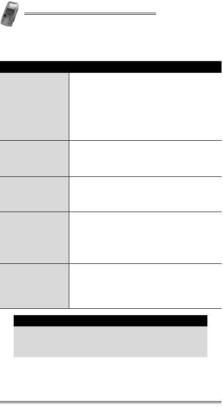
3. Specifications
Specification Details
Power
•Terminal 9 V at 4 A
•AC/DC Adapter (Safety Approved)
Input: 90-264 and 300 VAC
Output: 9 VDC at 4 A
3.3 V switching regulator
•The AC/DC Adapter must be approved by
the relevant authorities in the country
where the equipment is sold.
Dimensions
•Height: 80.7 mm (3.2 in)
Including the keypad privacy shield
•Width: 109.9 mm (4.3 in)
•Depth: 232.5 mm (9.2 in)
Weight
(approximate)
•POS terminal: 600 g (21.16 oz)
•Shipping weight may vary according to
optional accessories, documentation, and
packaging
Environmental
Requirements
•Operating temperature:
0° C to +50° C (+32° F to +122° F)
•Storage temperature:
-20° C to +60° C (-4° F to +140° F)
•Relative humidity:
5%-95% non-condensing
Modem
Communication
Rate
Choice of three speeds:
•14.4 Kbps
•56 Kbps
•56 Kbps and V.92
Note: Modem speed is model-dependent
Note
Specifications are subject to change without notice
due to changes to the device and its components.
The above specifications may differ between models of
the NURIT 8400.
NURIT 8400
Installation Manual 7
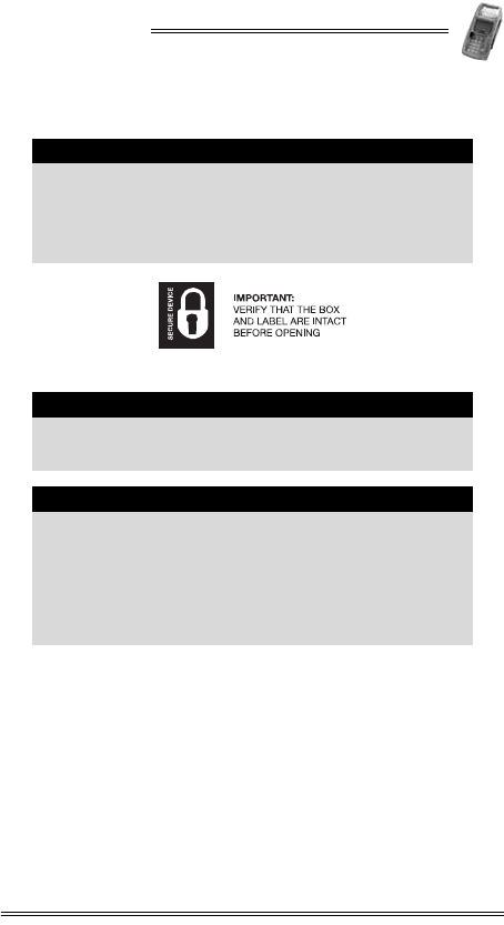
4. Initial Setup
Figure 4-1 Secure Device Label
Caution
The box of a secure NURIT device should be sealed
with a Secure Device label. If the Secure Device label
on the box was damaged or missing, this could be an
indication of device tampering and may affect the
validity of the warranty for the device. Notify your
VeriFone service provider.
Note
The size, appearance and precise wording of the
Secure Device label may vary according to the
particular service provider of the device.
Caution
•Carefully inspect the contents of the box for any
damaged or missing components. Do not use a
NURIT device that shows any signs of damage.
•VeriFone has taken all measures to provide you
with a complete device. If shipping damage is
evident, file a claim with the shipping company.
Notify your VeriFone service provider concerning
this damage, and if any components are missing.
NURIT 8400
8 Installation Manual
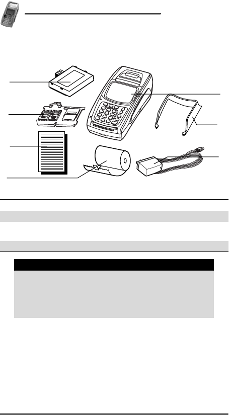
Contents Checklist
Figure 4-2 NURIT 8400 - Box Contents
Selecting a Point-of-Sale Location
The NURIT 8400 is designed to be operated in the following
locations:
•Indoors, using the AC/DC Power Adapter.
•Outdoors, powered only by a VeriFone-supplied or approved
battery.
1NURIT 8400 2Keypad privacy shield
3AC-DC power adapter 4Battery (model-dependent)
5SAM-SD/MMC Adapter
(model-dependent) 6Documentation pack
7Paper roll
Note
•Box contents may vary according to the specific
model.
•Some or all of the accessories contained in the box
may already be installed in the terminal.
•The contents of the documentation pack may vary
according to customer requirements.
3
1
4
5
2
6
7

NURIT 8400
Installation Manual 9
•When not operated from its hand-held position, place the
NURIT 8400 on a flat table or countertop close to a power
outlet and any peripherals.
•Maintain good ventilation around the terminal. Provide for
at least 22 cm (8.5 in) of clear space around the terminal in
its fixed operating location.
•Do not cover the terminal.
Warning
Do not locate the POS terminal where it can exposed
to the following:
•Devices that radiate excessive electrical noise or
voltage fluctuations, such as air conditioners, fans,
electric motors, neon signs, or high-frequency
security devices.
•Water containers, such as a sink, a laundry tub or
a pool.
•Areas of excessive moisture, heat, oil, dust or
debris.
•Direct sunlight or objects that radiate heat.
•Metal partitions or such obstructions that may
disrupt radio transmission or reception if your
terminal is used as a wireless device.
Caution
The NURIT 8400 should not be powered or charged
outdoors using its AC/DC adapter.
Caution
Some NURIT 8400 may have an optional internal radio
installed. If you are operating a terminal with this
feature, do not operate on a metal plate or near
metallic objects.
Note
Before using the NURIT 8400, remove the transparent
plastic membrane that covers the LCD screen.
NURIT 8400
10 Installation Manual
Note
To ensure compliance of the NURIT 8400 as a secure
PIN entry device:
•The customer should be able to obstruct visual
observation of the PIN entry with his/her body and
hand.
•The cardholder must be clearly instructed to
obstruct visual observation of the PIN entry with
his/her body and hand.
Failure to comply with these conditions may render
the terminal non-compliant with ISO 9564 for PIN
protection and may violate card association
requirements for PIN entry devices.
For more information, contact your local VeriFone
representative or service provider.
Caution
•A keypad privacy shield is preinstalled on all
models of the NURIT 8400. Do not attempt to
tamper or remove the privacy shield. Tampering
with the privacy shield may damage the device
and make it inoperable.
•If for any reason, the keypad privacy shield needs
to be replaced, contact a VeriFone service
representative.
Note
Do not use a NURIT 8400 that shows any sign of
damage.
NURIT 8400
Installation Manual 11
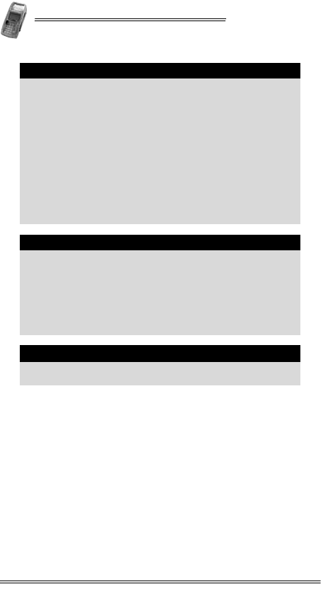
5. General Features
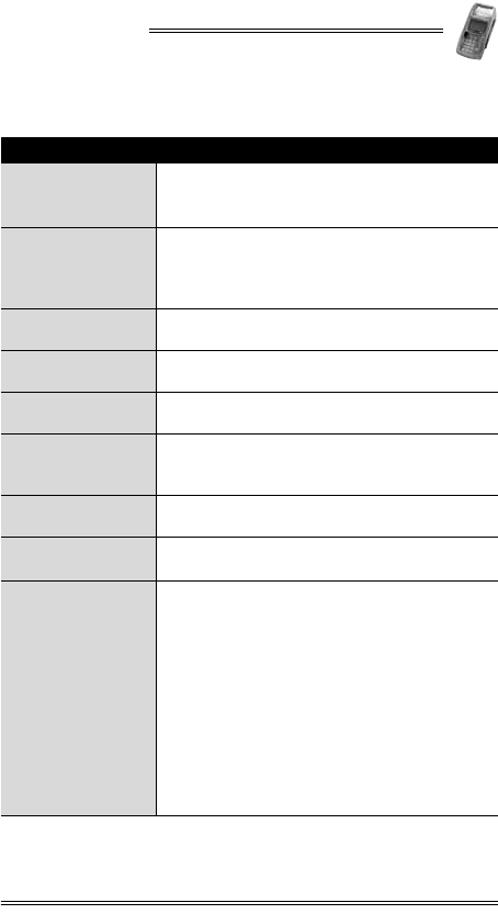
Feature Description
LCD Display •Graphical LCD display
•Black and white with backlight
•128 x 64 pixels, 63 x 35 mm
Keypad
20 keys comprised of:
•10-key telephone-style keypad
•10 Function and special keys
Four optional ATM-like keys
Smart Card Reader •Integrated, front-entry, EMV-compliant,
smart card reader
Magnetic Stripe
Card Reader •Integrated, bi-directional 3-track magnetic
stripe card reader
Keypad Privacy
Shield •Preinstalled privacy shield
SAM-SD/MMC
Adapter
•Up to four SAM cards (0, 2, 4)
•Up to two SAM (0, 2) and one SD/MMC card
Note: Configuration is model-dependent
SIM Slot •Slot for the insertion of a SIM card
Note: SIM card is model-dependent
Thermal Printer •Integrated printer uses thermal paper
•Easy-load mechanism
Connectors
•PWR (Power) Connector
•COM1 and COM2 RS-232 Connectors (COM2
is model dependent)
•TEL Connector (RJ-11)
•LINE Connector (RJ-11)
•PIN (PIN pad) Connector
•ENET, 10BaseT Ethernet LAN via Ethernet
Connector
•RS-485 LAN
•USB Host Connector (“A” Plug)
•USB Device Connector (“mini-B” Plug)
Note: Configuration is model-dependent
NURIT 8400
12 Installation Manual
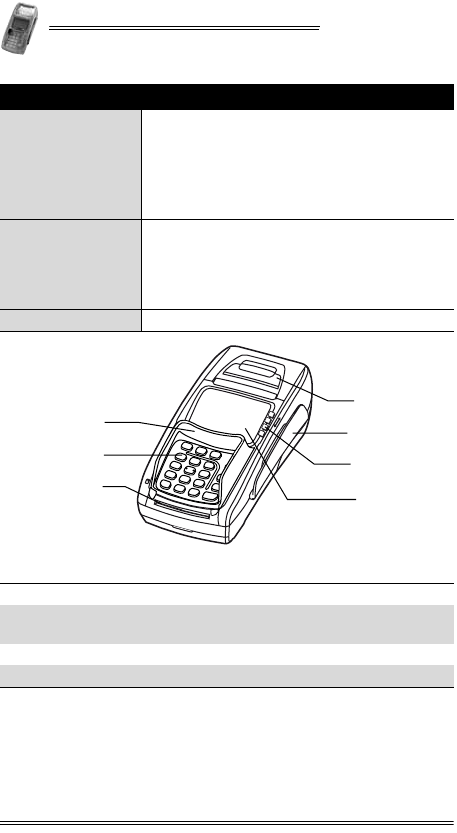
Figure 5-1 NURIT 8400 - Top View
Battery
•Two cell Lithium-ion (Li-Ion) battery
•Supplies 7.4 V at 2200 mAH (minimum)
•Fully recharges within six hours
•Smart monitor communication
•Charger included
Note: Battery is model-dependent
Radio
•Internal antenna
Choice of:
•GSM/GPRS
•CDMA
Note: Radio is model-dependent
Modem Choice of three speeds (model-dependent).
1Paper cover 2Magnetic stripe card slot
3ATM-like keys
(model-dependent) 4LCD display
5Keypad privacy shield 6Keypad
7Smart card slot
Feature Description
5
6
7
1
3
2
4
NURIT 8400
Installation Manual 13
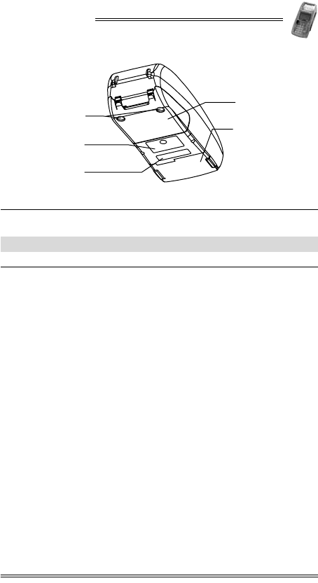
Figure 5-2 NURIT 8400 - Bottom View
1Cable compartment cover 2Battery/SAM-SD/MMC
compartment
3Rubber stop 4Compliance label
5Model/serial number label
1
2
3
4
5
NURIT 8400
14 Installation Manual
6. Removing and Replacing the Cable
Compartment Cover
The cable connection panel on the NURIT 8400 is located on
the bottom of the base unit, behind a cover for the cables. The
cables cover must be removed before you can connect the
terminal to the power supply, telephone line, or peripheral
devices.
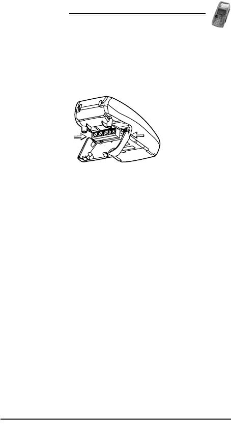
To remove the cable compartment cover:
1. Carefully hold the NURIT 8400 face down or place it on a
soft, smooth surface, so as not to damage the LCD display.
2. Steady the unit with one hand, with the bottom of the
terminal facing you.
3. On the cable compartment cover, place a finger in the
groove of each of the two locking tabs.
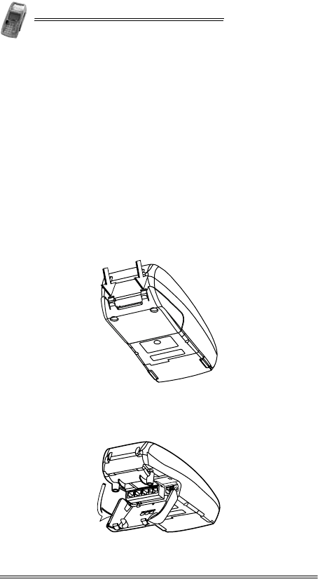
Figure 6-1 Opening the Cover Locking Tabs
4. Pull and lift the cover, exposing the terminal connectors.
5. Remove the connectors cover.
Figure 6-2 Lifting the Cable Compartment Cover
NURIT 8400
Installation Manual 15
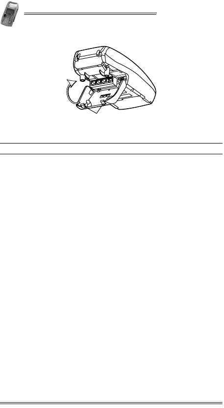
To replace the cable compartment cover:
1. Hold the cover at a 40° angle, with the hinge tabs facing
down.
2. Insert the hinge tabs into the tab slots, located above the
connectors.
Figure 6-3 Positioning the Cable Compartment Cover
3. Lower the cover and press down until the locking tabs snap
into place.
NURIT 8400
16 Installation Manual
Figure 6-4 Closing the Cable Compartment Cover
1Cable compartment cover locking tabs
1
NURIT 8400
Installation Manual 17
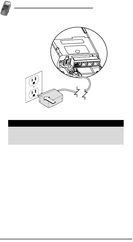
7. Connecting to the Power Supply
To connect the NURIT 8400 to the power supply:
1. Remove the cable compartment cover, as described in
“Removing and Replacing the Cable Compartment Cover”
on page 14.
2. Connect the barrel plug on the AC/DC Power Adapter cable
to the connector labeled PWR on the rear panel of the
terminal.
3. Connect the other end of the AC/DC Power Adapter cable to
an electrical power outlet.
4. Replace the cable compartment cover, as described on
page 15.
Warning
Use only the VeriFone supplied AC/DC Power Adapter
to power the NURIT 8400.
Warning
Do not plug the AC/DC Power Adapter into an outdoor
electrical power outlet.
Caution
Disconnecting the terminal from the power outlet will
disrupt the transaction process.
NURIT 8400
18 Installation Manual
Figure 7-1 Power Supply Connection
Note
It is recommended that you install a power surge
arrestor at the power outlet to prevent possible
damage caused by electrical spikes or local lightning
strikes.
NURIT 8400
Installation Manual 19
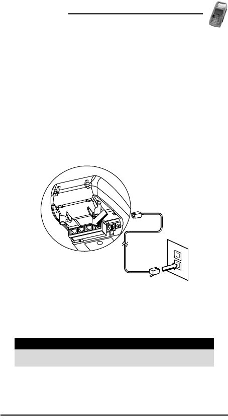
8. Connecting to a Telephone Line
To connect the NURIT 8400 to a standard analog modular
telephone line:
1. Disconnect the AC/DC Power Adapter from the electrical
power outlet.
2. Remove the cable compartment cover, as described in
“Removing and Replacing the Cable Compartment Cover”
on page 14.
3. Insert the telephone cord supplied with the terminal into
the LINE connector on the rear panel of the terminal.
4. Connect the other end of the telephone cord into a standard
RJ-11 type modular telephone line outlet.
Figure 8-1 NURIT 8400 - Telephone Line Connection
5. Replace the cable compartment cover, as described on
page 15.
6. Reconnect the AC/DC Power Adapter to the electrical
power outlet.
Caution
Only use the assigned connection port, labeled LINE for
telephone line connections.
LINE
NURIT 8400
20 Installation Manual
Telephone Outlet Types
The following types of telephone outlets are common:
•Modular
This is the most common type of telephone outlet used. Plug
the supplied telephone cord from the terminal into a stan-
dard modular telephone connector. If you do not have a
modular connector, contact your local telephone company
or a qualified telephone technician.
•4-Prong Connector
You must purchase a special adapter for use with a 4-prong
connector. This adapter plugs into the 4-prong connector
and the telephone line cord plugs into the adapter.
•Hard-wired
You must purchase a special modular connector adapter for
this direct-type hard-wire connection that replaces older
connecting blocks. Contact your local telephone company
or a qualified telephone technician for correct information
on color-coded connections.
Note
It is recommended that you use a dedicated telephone
line with the NURIT 8400. In some models the phone
line is disabled during transactions
Note
Use only the telephone cord shipped with the terminal.
Using a different telephone cord may cause the
terminal to malfunction.
NURIT 8400
Installation Manual 21
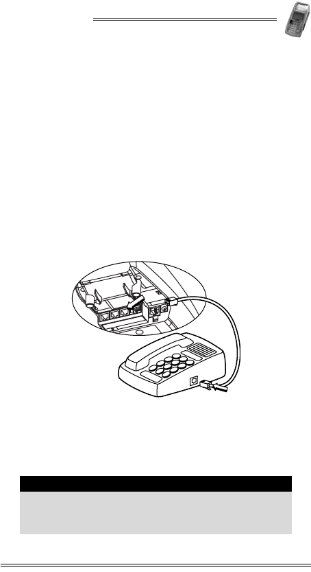
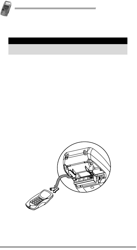
9. Connecting an External Telephone
You can connect a standard external telephone to a model of the
NURIT 8400 that uses the analog telephone network for
communications and does not support a LAN connection.
To connect an external telephone to the NURIT 8400:
1. Disconnect the AC/DC Power Adapter from the electrical
power outlet.
2. Remove the cable compartment cover, as described in
“Removing and Replacing the Cable Compartment Cover”
on page 14.
3. On the rear panel of the NURIT 8400, insert one end of a
telephone cord (model dependent, VeriFone supplied) into
the TEL connector.
4. Insert the other end of the telephone cord into the RJ-11
type modular connector on the base of the telephone.
Figure 9-1 External Telephone Connection
5. Replace the cable compartment cover, as described on
page 15.
6. Reconnect the AC⁄DC Power Adapter to the electrical power
outlet.
Note
If you want to connect an external telephone to the
NURIT 8400 terminal, along with an analog telephone
network connection, you must use a 2-socket RJ-11
plug in the modular wall connector.
TEL
NURIT 8400
22 Installation Manual
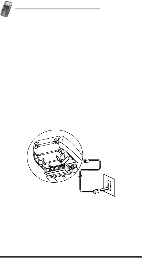
10. Connecting to a LAN
Some models of the NURIT 8400 can be connected to a Local
Area Network (LAN). Depending on the specific model, the
NURIT 8400 can be connected to either an RS-485 LAN or a
10BaseT Ethernet LAN.
To connect the NURIT 8400 to an Ethernet LAN:
1. Disconnect the AC/DC Power Adapter from the electrical
power outlet.
2. Remove the cable compartment cover, as described in
“Removing and Replacing the Cable Compartment Cover” on
page 14.
3. Connect the Ethernet Adapter cable to the ENET connector
on the connections panel.
4. Connect the other end of the Ethernet Adapter cable to one
end of the network cable.
5. Connect the other end of the network cable to a network
wall outlet, switch, or other compatible network device.
Figure 10-1 Typical Ethernet/RS-485 LAN Connection
6. Replace the cable compartment cover, as described on
page 15.
7. Reconnect the AC/DC Power Adapter to the electrical
power outlet.

NURIT 8400
Installation Manual 23
To connect the NURIT 8400 to an RS-485 LAN:
1. Disconnect the AC/DC Power Adapter from the electrical
power outlet.
2. Remove the cable compartment cover, as described in
“Removing and Replacing the Cable Compartment Cover” on
page 14.
3. Connect the network cable to the RS-485 connector on the
connections panel.
4. Connect the other end of the network cable to a network
wall outlet, switch, or other compatible network device.
5. Replace the cable compartment cover, as described on
page 15.
6. Reconnect the AC/DC Power Adapter to the electrical
power outlet.
NURIT 8400
24 Installation Manual
11. Connecting an External PIN Pad
To connect an external PIN pad to the NURIT 8400:
1. Disconnect the AC/DC Power Adapter from the electrical
power outlet.
2. Remove the cable compartment cover, as described in
“Removing and Replacing the Cable Compartment Cover” on
page 14.
3. Connect one end of the connector cable (supplied with the
terminal) to the PIN connector on the rear panel of the
NURIT 8400.
4. Verify that the other end of the connector cable is
connected to the PIN pad.
5. Replace the cable compartment cover, as described on
page 15.
6. Reconnect the AC/DC Power Adapter to the electrical
power outlet.
Figure 11-1 PIN Pad Connection
Caution
Only use the assigned connection port, labeled PIN for
PIN pad connections.
PIN
NURIT 8400
Installation Manual 25
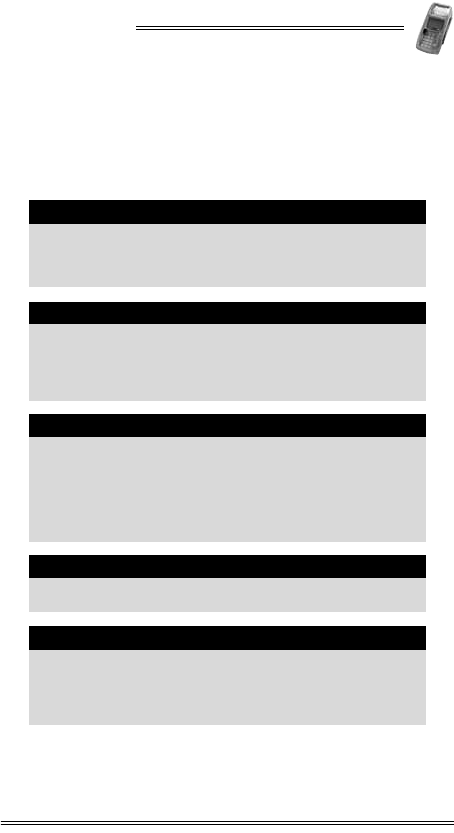
12. Connecting Peripheral Devices
Models of the NURIT 8400 may include ports, allowing
connection of the terminal to external devices, such as:
•RS-232 connector
•USB connector
Caution
•Turn off the POS terminal, ECR, or PC whenever
you connect or disconnect the NURIT 8400.
•Do not disconnect the NURIT 8400 when the POS
terminal, ECR, or PC is processing data.
Caution
You can connect to up to four external peripheral
devices to the NURIT 8400. Consult with your
VeriFone service provider for information about the
peripheral devices that you can connect to your
specific model.
Note
Peripheral devices may require special adapter cables
for their connection to the NURIT 8400. In addition,
certain peripheral devices require an external power
supply.
Refer to the product documentation of the specific
peripheral devices, or contact your local VeriFone
representative or service provider for further details.
Note
USB peripheral support requires the installation of a
corresponding driver.
Note
The COM1 port provides a power supply for peripheral
devices. The power supply is 6 VDC (minimum)-9 VDC
(maximum) at 250 mA. This also applies to the
model-dependent COM2 port, when there is no PIN pad
connection.
NURIT 8400
26 Installation Manual
To connect an RS-232 peripheral device to the
NURIT 8400:
1. Disconnect the AC/DC Power Adapter from the electrical
power outlet.
2. Remove the cable compartment cover, as described in
“Removing and Replacing the Cable Compartment Cover” on
page 14.
3. Connect a peripheral device to one end of its adapter cable.
4. Connect the other end of the adapter cable to either the
COM1 or COM2 (model-dependent) connector on the
connections panel.
5. Replace the cable connection cover, as described on
page 15.
6. Reconnect the AC/DC Power Adapter to the electrical
power outlet.
Figure 12-1 Peripheral Device Connection
1Signature capture device 2PC
3Barcode reader 4Electronic scale
5Check reader 6Contactless reader
PWR
COM1
COM2
1
2
3
4
5
6
NURIT 8400
Installation Manual 27
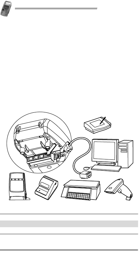
To connect a USB peripheral device to the NURIT 8400:
1. Disconnect the AC/DC Power Adapter from the electrical
power outlet.
2. Remove the cable connection cover, as described in
“Removing and Replacing the Cable Compartment Cover” on
page 14.
3. Insert the USB plug into the USB connector on the
peripheral device.
4. Insert the USB plug into the USB connector on the
NURIT 8400 terminal.
Figure 12-2 Typical Connection to an ECR
Figure 12-3 Typical USB Connection to a PC-POS
5. Replace the cable connection cover, as described on
page 15.
6. Reconnect the AC/DC Power Adapter to the electrical
power outlet.
DRAWER
ETHERNET DISPLAY EXT.KB BARCODE
LINE
PHONE
PC PORT
PIN
PAD
POWER
COM1 COM2
RS-232
USB
USB
USB
NURIT 8400
28 Installation Manual
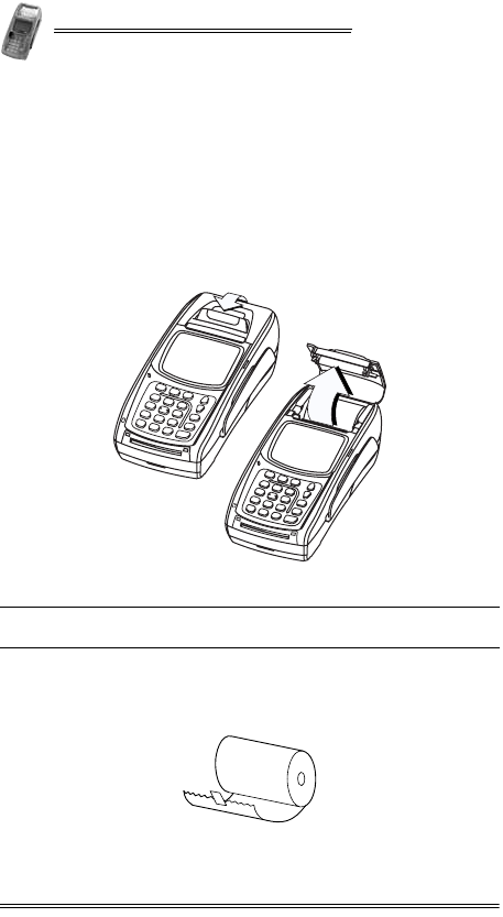
13. Loading Paper in the Printer
To load a roll of thermal paper in the printer:
1. Place the terminal on a flat, stable surface.
2. Insert two fingers into the recess on the paper
compartment cover, beneath the release latch.
3. Pull the opening latch up until the cover unlocks.
4. Lift the paper compartment cover until it is fully open.
Figure 13-1 Opening the Paper Compartment
5. Remove the tape strip from a new paper roll.
6. Unroll approximately 5 cm (2 in) of paper to facilitate the
loading process.
Figure 13-2 Unrolling the Paper Roll
1Opening the paper cover
latch 2Opening the paper
compartment
2
1
NURIT 8400
Installation Manual 29
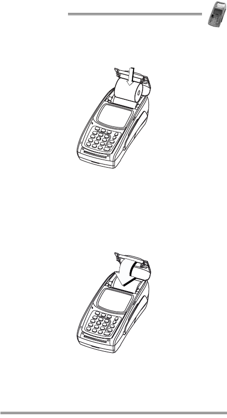
7. Hold the paper roll with the unrolled end on the underside.
8. Lower the paper roll into the paper compartment.
Figure 13-3 Inserting a Paper Roll
9. Pull the unrolled end of the paper approximately 2.5 cm
(1 in) out of the paper compartment, ensuring that the
paper feeds from the underside of the roll.
10. Make sure that the opening latch is down, in its original
position.
11. Close the paper compartment cover, pressing press down
firmly, until it snaps into place.
Figure 13-4 Closing the Paper Compartment
NURIT 8400
30 Installation Manual
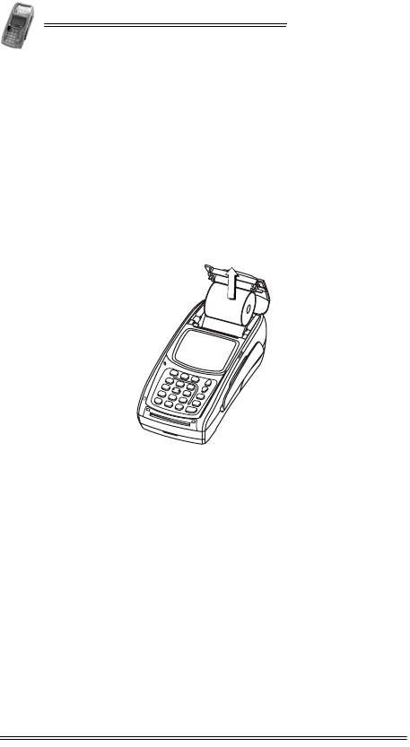
Removing the Paper Roll from the Printer
To remove an empty roll of thermal paper from the
printer:
1. Place the terminal on a flat, stable surface.
2. Insert two fingers into the recess on the paper
compartment cover, beneath the release latch.
3. Pull the opening latch up until the cover unlocks.
4. Lift the paper compartment cover until it is fully open, as
illustrated in Figure 13-1 on page 28.
5. Lift the paper roll out of the paper compartment.
Figure 13-5 Removing the Paper Roll
NURIT 8400
Installation Manual 31
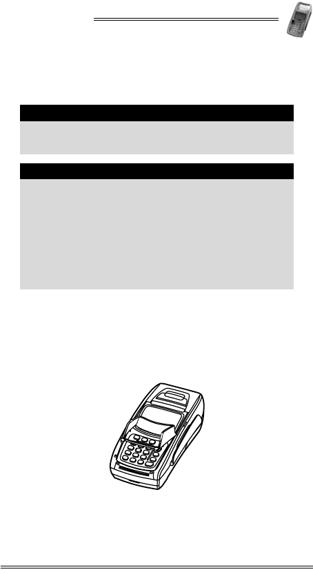
14. Installing and Removing the Keypad
Privacy Shield
To install the keypad privacy shield:
1. Place the terminal on a flat, stable surface, or hold it
securely in one hand.
2. Hold the keypad privacy shield above the terminal.
3. Tilt one side of the keypad privacy shield downward at an
angle of approximately 30°.
Figure 14-1 Installing the Keypad Privacy Shield
Note
The keypad privacy shield is included only with models
of the NURIT 8400 that are designed for secure PIN
entry.
Note
In addition to the installation of the keypad privacy
shield, the cardholder must be clearly instructed to
obstruct visual observation of the PIN entry with
his/her body and hand. (See “Selecting a Point-of-Sale
Location” on page 8.)
Failing to install or removing the keypad privacy
shield, or failing to instruct the cardholder to obstruct
visual observation of the PIN entry with his/her body
and hand, may render the terminal non-compliant with
ISO 9564 for PIN protection and may violate card
association requirements for PIN entry devices.

NURIT 8400
32 Installation Manual
4. Insert the curved tab on the back side of the keypad privacy
shield into the circular opening positioned on either side of
the terminal (on either side of the top of the keypad area).
5. Push down on the same side’s front of the keypad privacy
shield, until the front tab snaps into place.
6. Position the second tab, at the front of the terminal, into the
tab slot.
7. Push down on the remaining corner of the keypad privacy
shield, until it snaps into place.
To remove the keypad privacy shield:
1. Place the terminal on a flat, stable surface, or hold it
securely in one hand.
2. Grasp either side of the keypad privacy shield.
3. Squeeze and pull on a diagonal one of the back side tabs of
the privacy shield until the back side tab releases.
4. Pull the keypad privacy shield away from the terminal.
NURIT 8400
Installation Manual 33
15. Removing and Replacing the
Battery/SAM-SD/MMC Compartment
Cover
To remove the battery/SAM-SD/MMC compartment cover:
1. Disconnect the AC/DC Power Adapter from the electrical
power outlet.
2. Carefully turn the NURIT 8400 face down or place it on a
soft, smooth surface, so as not to damage the LCD display.
3. Steady the unit with one hand.
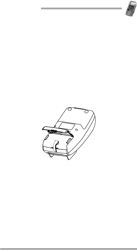
4. With your other hand, use your thumb to press in and lift
the compartment cover.
5. Remove the battery/SAM-SD/MMC compartment cover.
Figure 15-1 Removing the battery/SAM-SD/MMC
Compartment Cover
NURIT 8400
34 Installation Manual
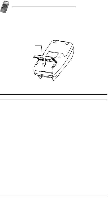
To replace the battery/SAM-SD/MMC compartment cover:
1. Insert the two hinge tabs of the battery/SAM-SD/MMC
compartment cover into the tab slots on the edge of the
compartment.
Figure 15-2 Replacing the battery/SAM-SD/MMC
Compartment Cover
2. Lower the compartment cover, using your thumb to press in
the locking tab.
3. Press in the locking tab and push down the compartment
cover until the cover snaps into place.
1Cover locking tab
1
NURIT 8400
Installation Manual 35
16. Installing and Removing the Battery
To install the battery:
1. Remove the battery/SAM-SD/MMC compartment cover, as
described in “Removing and Replacing the Battery/SAM-SD/MMC
Compartment Cover” on page 33.
2. If necessary, remove the SAM-SD/MMC adapter, as
described in “Installing and Removing the SAM-SD/MMC
Adapter” on page 38.
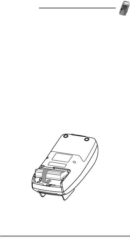
3. Hold the battery at a 30° angle, with the battery power
plug, facind down, into the compartment, making sure that
the side with the arrow pictogram is facing upward.
4. Slide the two tabs on the front of the battery into the slots
on the front wall of the battery compartment.
5. Slide the battery forward and down, until it snaps into
place.
6. If necessary, install the SAM-SD/MMC adapter, as described
in “Installing and Removing the SAM-SD/MMC Adapter”
on page 38.
7. Replace the battery/SAM-SD/MMC compartment cover, as
illustrated in Figure 15-2 on page 34.
Figure 16-1 Installing the Battery
NURIT 8400
36 Installation Manual
To remove the battery from the NURIT 8400:
1. Remove the battery/SAM-SD/MMC compartment cover, as
described in “Removing and Replacing the Battery/SAM-SD/MMC
Compartment Cover” on page 33.
2. If necessary, remove the SAM-SD/MMC adapter, as
described in “Installing and Removing the SAM-SD/MMC
Adapter” on page 38.
3. Slide the battery in the direction of the arrow, gently
detaching it from its socket.
4. Remove the battery.
Battery Maintenance
•The supplied high-performance, smart Lithium-Ion battery
provides 7.2 V at 2200 mAH (minimum) capacity.
•When fully discharged, the battery fully recharges within
six hours while installed in the terminal.
•The terminal can be connected to an AC/DC power supply
indefinitely without causing damage to the battery.
•In typical use, the life span of the battery exceeds 500
charge cycles, after which, operating time decreases slowly.
•The battery has a self-discharge rate. It loses approximately
1% of its charge per day when not in use. Replace the
battery when the charge capacity is too weak for normal
operation.
•Remove the battery from the terminal if you do not intend
to use your NURIT 8400 for an extended period of time.
Caution
Take care when installing the battery. If installed
incorrectly, it may explode. Use only a VeriFone
supplied battery.
Warning
Do not break open or damage the casing of the battery.
Warning
Do not dispose of the NURIT 8400 Li-Ion smart battery
in a fire. Li-Ion batteries must be recycled or disposed
of properly. Do not dispose of Li-Ion batteries in
municipal waste sites.

NURIT 8400
Installation Manual 37
Note
Extreme temperatures degrade the battery
performance.
Battery Environmental Requirements:
•Charge: 0°C to 45°C (32°F to 113°F)
•Discharge: -30°C to 60°C (-22°F to 140°F)
•Storage: -20°C to 45°C (-4°F to 113°F)
Note
To power on a terminal from “OFF” state, while using
a battery, press the bottom left button of the keypad.
NURIT 8400
38 Installation Manual
17. Installing SIM, SAM, and
SD/MMC Cards
Depending on the particular model, you can install a variety of
electronic memory or processing cards in the NURIT 8400:
•Up to four (4) SAM (Secure Access Module) cards can be
installed in SAM cardholders (2, 4), located on the
NURIT 8400’s SAM-SD/MMC adapter. SAM cards may be
used to hold encryption keys, identify the terminal or
merchant to the host, process applications, or a variety of
other uses.
•One (1) SD (Secure Digital) or MMC (Multi-Media Card)
cards, alongside up to two (2) SAM cards (0, 2). SD and
MMC cards hold data, such as price lists and offline
transaction information, where supported by the
application.
With any of these options, you can install a SIM Card for your
wireless transactions.
.
Installing and Removing the SAM-SD/MMC
Adapter
Before using a terminal with SAM and/or SD/MMC cards, the
adapter must be installed.
To install the SAM-SD/MMC adapter:
1. Remove the battery/SAM-SD/MMC compartment cover, as
described in “Removing and Replacing the Battery/SAM-SD/MMC
Compartment Cover” on page 33.
2. If required, install the battery, as described in “Installing and
Removing the Battery” on page 35.
Caution
Do not store any foreign objects in the
battery/SAM-SD/MMC adapter compartment.
Caution
The contacts on the SAM, SIM, SD/MMC, and
cardholders can be easily damaged. Do not bend or
scratch when installing or removing the cards.
NURIT 8400
Installation Manual 39
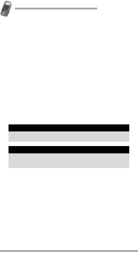
3. Hold the SAM-SD/MMC adapter with the cardholders
facing upwards, and connector towards the terminal socket.
4. Hold the SAM-SD/MMC adapter on a 30° angle, so that the
front tabs, on both the right and left of the board are in the
front slots.
5. Gently push the adapter down, resting it in the grooves on
the sides of the compartment.
6. Slide the adapter forward, until the locking button locks
into place.
7. Replace the battery/SAM-SD/MMC compartment cover, as
illustrated in Figure 15-2 on page 34.
Figure 17-1 Installing the SAM-SD/MMC Adapter
To remove the SAM-SD/MMC adapter:
1. Remove the battery/SAM-SD/MMC compartment cover, as
described in “Removing and Replacing the Battery/SAM-SD/MMC
Compartment Cover” on page 33.
2. Press the adapter connector down, unlocking the adapter
from the socket.
3. Slide and lift the SAM-SD/MMC adapter out of the
compartment.
1Locking button 2Right insertion groove
3Front right insertion tab 4Locking button hole
5Back right insertion tab 6 Left insertion groove
7Front left insertion tab 8SAM-SD/MMC adapter
connector
9 Back left insertion tab
9
6
7
8
1
2
3
4
5
NURIT 8400
40 Installation Manual
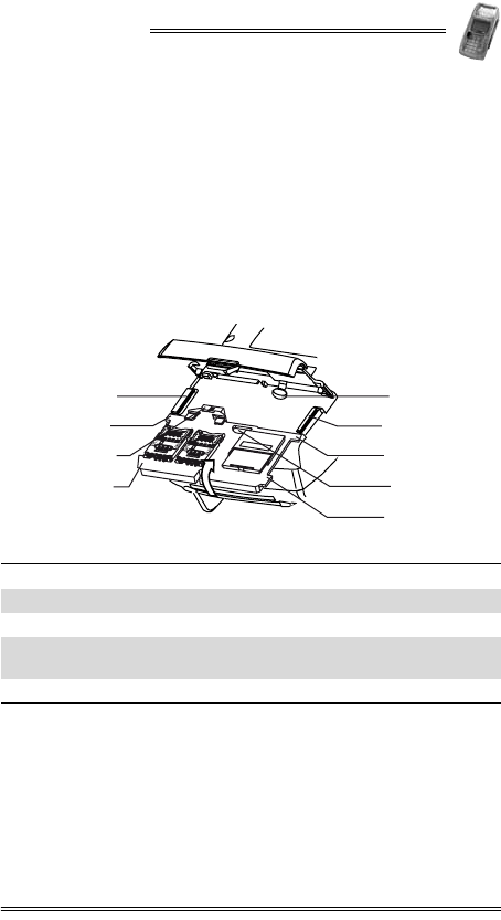
SAM and SD/MMC Card Configurations
Figure 17-2 SAM and SD/MMC Cards Configurations
Installing a SAM Card
The NURIT 8400 includes a slot to install a SAM card, which is
required if the terminal implements wireless communication
technology.
To install a SAM card:
1. Remove the battery/SAM-SD/MMC compartment cover, as
described in “Removing and Replacing the Battery/SAM-SD/MMC
Compartment Cover” on page 33.
2. Slide the cardholder locking-clasp in the direction indicated
by the engraved arrow to the OPEN position.
Configuration Description
A
•Two SAM cards are installed in the two SAM
cardholders.
•An SD/MMC card is installed in the
SD/MMC card slot.
B•Two SAM cards are installed in the two SAM
cardholders.
C•Four SAM cards are installed in the four SAM
cardholders.
SAM SAM
AB C
SAMSAM
SD/MMC SAM SAMSAM
SAM
NURIT 8400
Installation Manual 41
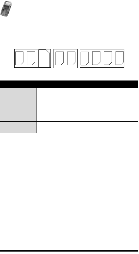
Figure 17-3 SAM Cardholder Locking-Clasp
3. Lift the cardholder on its hinge to an upright position.
4. Hold the SAM card so that its chip side is facing down
towards the contacts on the reader.
5. Insert the end closest to the chip on the SAM card into the
cardholder.
Figure 17-4 SAM Card Installation
1Locking clasp
Note
Make sure that you first slide the end closest to the
chip on the card into the grooves of the holder.
1SAM card 2Beveled corner
3Metal contacts 4Triangular protrusion
1
12
3
4
NURIT 8400
42 Installation Manual
6. Close the SAM cardholder.
7. Lock the cardholder by sliding the cardholder locking clasp
in the direction indicated by the engraved arrow to the
LOCK position.
8. Replace the battery/SAM-SD/MMC compartment cover, as
described on page 34.
Installing an SD/MMC Card
To install an SD/MMC card:
1. Remove the battery/SAM-SD/MMC compartment cover, as
described in “Removing and Replacing the Battery/SAM-SD/MMC
Compartment Cover” on page 33.
2. Hold the SD/MMC card directly above the SD/MMC card
slot, with the metal contacts facing down and the narrow
edge with the beveled corner pointing towards the slot
opening.
3. Slide the SD/MMC card into the cardholder.
4. Press down on the SD/MMC card while sliding it into the
slot.
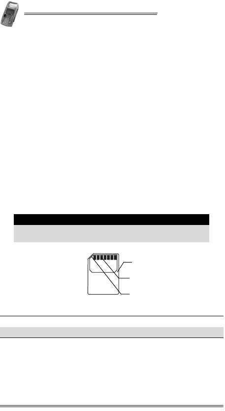
Figure 17-5 SD/MMC Card
5. Replace the battery/SAM-SD/MMC compartment cover, as
described on page 34.
Note
Make sure that you first slide the end closest to the
chip on the card into the grooves of the holder.
1SD/MMC card 2Metal contacts
3Beveled corner
1
2
3
NURIT 8400
Installation Manual 43
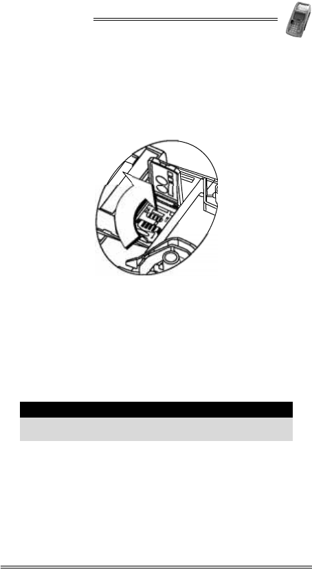
Installing a SIM card
To install a SIM card:
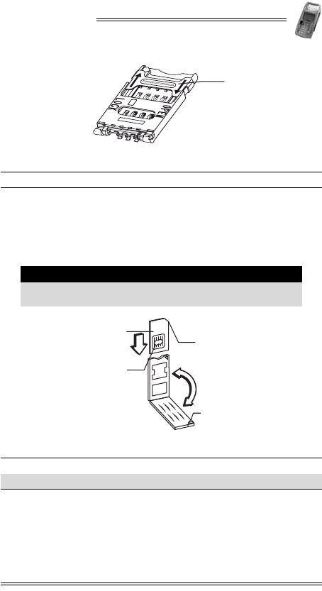
1. Remove the cables cover, as described in “Removing and
Replacing the Cable Compartment Cover” on page 14.
2. With a screwdriver, lift the tab of the SIM card cover.
Figure 17-6 Lifting the SIM Card Cover
3. Slide the cardholder locking-clasp in the direction indicated
by the engraved arrow to the OPEN position, as illustrated in
Figure 17-3.
4. Lift the cardholder on its hinge to an upright position.
5. Hold the SIM card so that its chip side is facing down
towards the contacts on the reader.
6. Insert the end closest to the chip on the SIM card into the
cardholder, as illustrated in Figure 17-4.
7. Close the SIM cardholder.
8. Lock the cardholder by sliding the cardholder locking clasp
in the direction indicated by the engraved arrow to the
LOCK position.
9. Replace the SIM card cover, by holding the SIM card cover
at a 30° angle and putting the tabs into the tab slots.
Note
Make sure that you first slide the end closest to the
chip on the card into the grooves of the holder.

NURIT 8400
Installation Manual 45
18. General Care and Maintenance
The NURIT 8400 is designed to give you long and trouble-free
service with minimal operator care.
Maintenance Recommendations
To maintain the NURIT 8400 in proper working condition:
•Keep the terminal dry and in the cleanest possible working
and storage environment.
•Do not store the terminal in extremely hot or cold areas.
•Do not shake or drop the terminal.
Cleaning the NURIT 8400
To clean the NURIT 8400:
•Gently wipe off dirt from the body of the terminal with a
soft, damp, lint-free cloth. A very mild dishwashing
detergent can be used to dampen the cloth.
•Alcohol or alcohol-based cleansers may also be used for
stains that are more difficult.
•If available, a low-pressured blower can be used to remove
dirt accumulated around the keypad buttons.
•Use a soft cloth, an eyeglass lens wiper, or a lens blower to
remove dust and dirt from the LCD screen.
Caution
•There are no user serviceable parts or components
in the NURIT 8400.
•Opening or disassembling the POS terminal in any
way not specifically instructed in this manual will
automatically erase all secret encryption keys and
will render the POS terminal inoperable.
•Opening the NURIT 8400 terminal will void any
warranty and security certification. It may also
result in irreversible damage to the terminal’s
electronic circuitry.
NURIT 8400
46 Installation Manual
Shipping the NURIT 8400
In exceptional circumstances, you may be required to ship your
NURIT 8400 to a servicing facility.
To ship the NURIT 8400:
1. Carefully pack the NURIT 8400, preferably in its original
box.
2. Send the package prepaid and adequately insured.
Technical Assistance
Contact your VeriFone representative or service provider for
technical assistance and ordering information regarding
specific components or accessories.
Caution
•Never use abrasive compounds or solvents,
thinners, benzene or synthetic cleansers.
•Never clean the keypad with liquids. Use only a
lightly dampened cloth or soft brush.
•Never rub or strongly press on the LCD display.
Note
•Notify a VeriFone representative or service
provider before shipping the NURIT 8400. In some
cases, you may be required to attach a letter to the
package detailing the problem and including
product information such as the serial number and
the date of purchase.
•Shipment must be to an authorized representative
or service center only. Contact your VeriFone
representative for the correct address.
NURIT 8400
Installation Manual 47
19. Troubleshooting
The NURIT 8400 has been designed for trouble-free operation,
though minor problems may occur during installation and use.
This section briefly describes how to troubleshoot some
possible common problems that may arise during the normal
operation of the NURIT 8400.
Before requesting service for the terminal, read this section to
find a possible remedy for the problem. If you are still unable to
solve the problem, contact a service representative. Do not try
to solve the problem by opening the terminal yourself.
The POS terminal appears to have no power
1. Check all cable connections.
2. If possible, try connecting the PIN pad to a different POS terminal
or ECR.
3. Try adjusting the LCD display contrast settings, using the
designated, model-dependent key combination.
4. If the problem persists, contact an authorized service
representative.
The keypad does not respond
1. Refer to user documentation for the particular application in use.
2. If the problem persists, contact an authorized service
representative.
An incorrect response or data is obtained
1. Refer to user documentation for the particular application in use.
2. If the problem persists, contact an authorized service
representative.
"Tampered Device" is displayed on the screen
and the PIN pad is inoperable
• Contact an authorized service representative.
NURIT 8400
48 Installation Manual
The magnetic stripe card reader does not function properly
1. Verify that the card has been swiped with its magnetic stripe at
the bottom and at the lower edge of the card. See Figure A-1
on page 49.
2. Swipe the magnetic stripe card in the opposite direction.
3. If possible, try using a different magnetic stripe card.
4. If the problem persists, contact an authorized service
representative.
The smart card reader does not function properly
1. Verify that the chip end of the smart card is fully inserted with the
chip side facing up. See Figure B-1 on page 50.
2. If possible, try using a different smart card.
3. If the problem persists, contact an authorized service
representative.
NURIT 8400
Installation Manual 49
Appendix A: Using the Magnetic Stripe
Card Reader
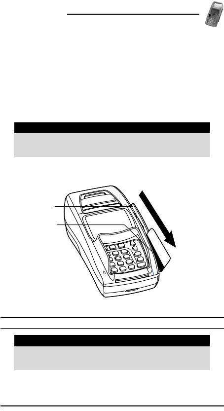
To use the magnetic stripe card reader:
1. Hold the card with the magnetic stripe positioned down and
facing left.
2. Insert the card into the top end of the card reader slot
located on the right side of the terminal.
3. Swipe the card in a smooth, continuous movement, all the
way through the slot.
Figure A-1 Using the Magnetic Stripe Card Reader
Note
A pictogram near the top end of the card slot indicates
how to insert and swipe the card through the magnetic
stripe card reader.
1Magnetic stripe card reader 2Magnetic stripe
Note
It is recommended that you swipe the card from top to
bottom, though the magnetic stripe card reader
supports bi-directional swiping of cards.
1
2
NURIT 8400
50 Installation Manual
Appendix B: Using the
Smart Card Reader
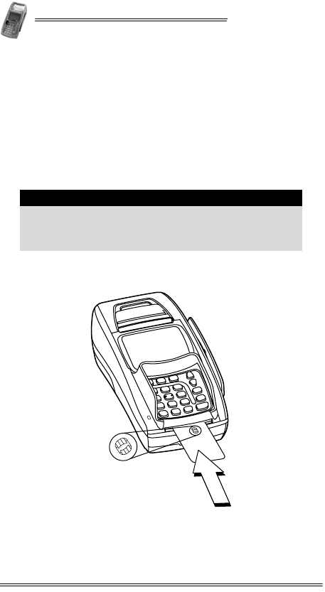
The EMV-compatible smart card reader is located at the front
end of the NURIT 8400.
To use the smart card reader:
1. Hold the smart card horizontally, with the metal chip facing
up and directed towards the NURIT 8400.
2. Insert the card into the smart card reader slot.
3. Remove the card when prompted by the POS terminal,
depending on the specific application being used.
Figure B-1 Using the Smart Card Reader
Note
For guidance, a pictogram near the card slot indicates
how to insert the smart card into the smart card
reader. In addition, insertion direction arrows may be
engraved or inscribed on the smart card.

NURIT 8400
Installation Manual 51
Installation Notes
NURIT 8400
52 Installation Manual
Contact Information
VeriFone, Inc.
2099 Gateway Place, Suite 600
San Jose, CA, 95110 USA
Tel: +1-800-VeriFone (837-4366)
www.verifone.com