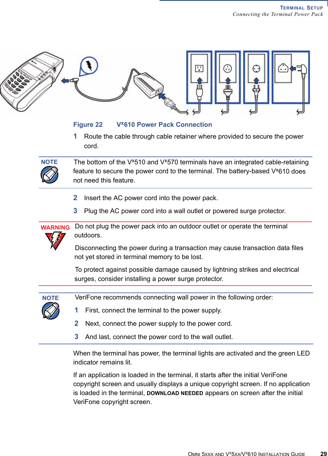
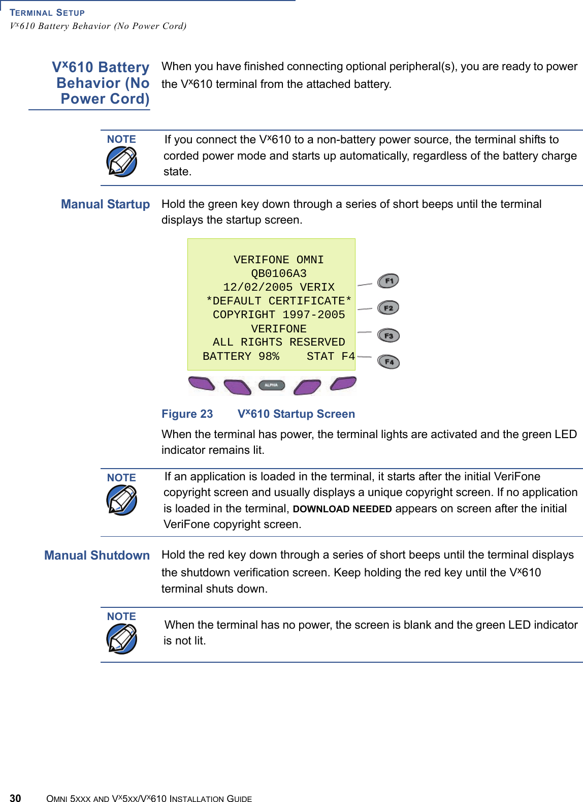
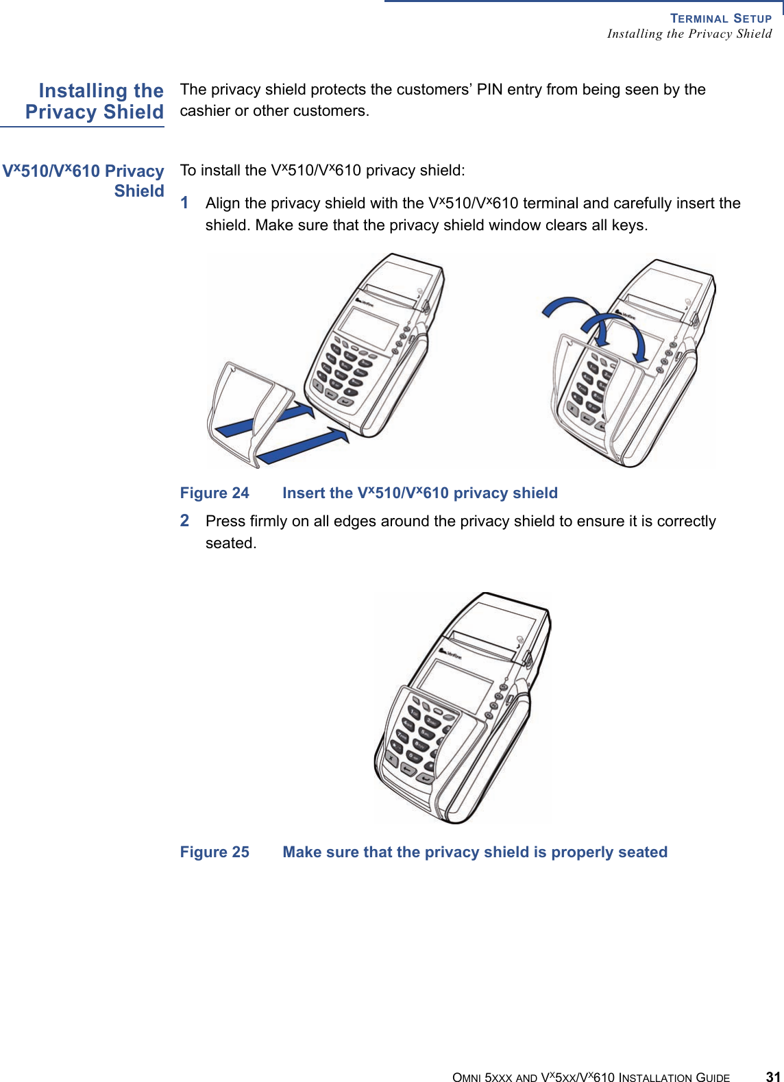
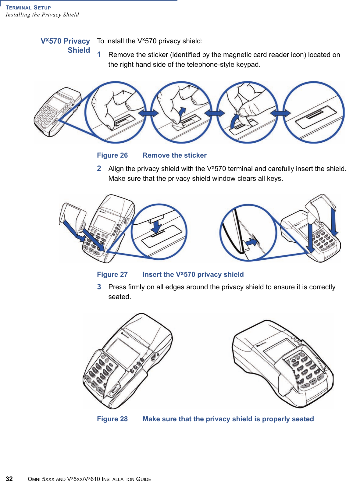
Verifone VX610C-M200 POINT OF SALES PAYMENT TERMINAL User Manual 23216 book
VeriFone Inc POINT OF SALES PAYMENT TERMINAL 23216 book
UserManual.wiki
>
Verifone
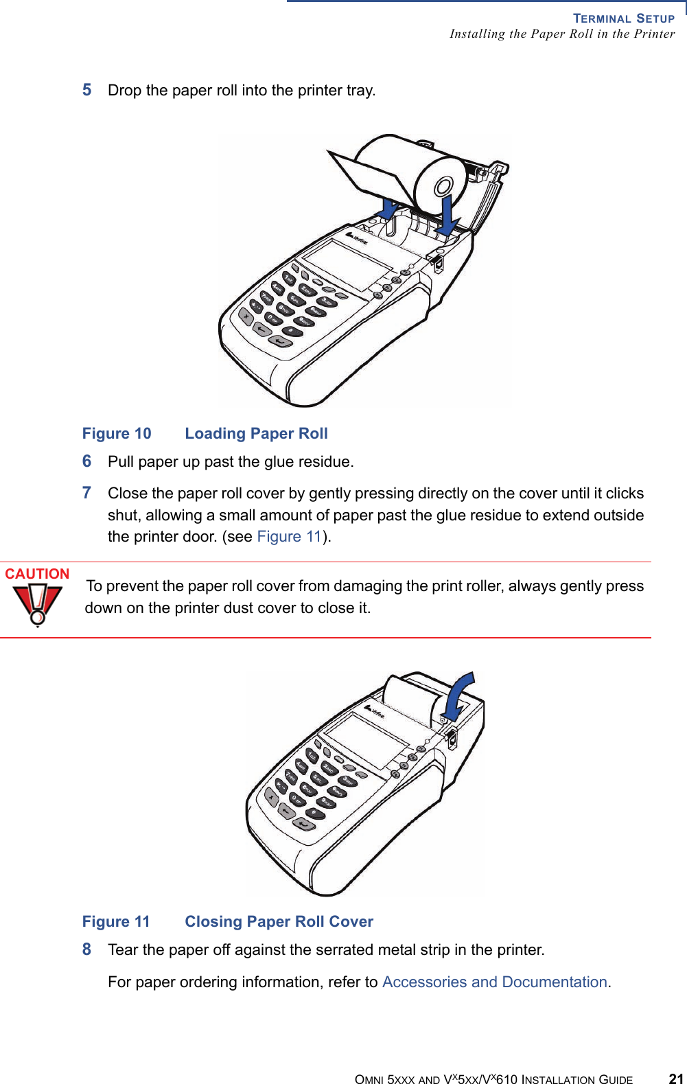
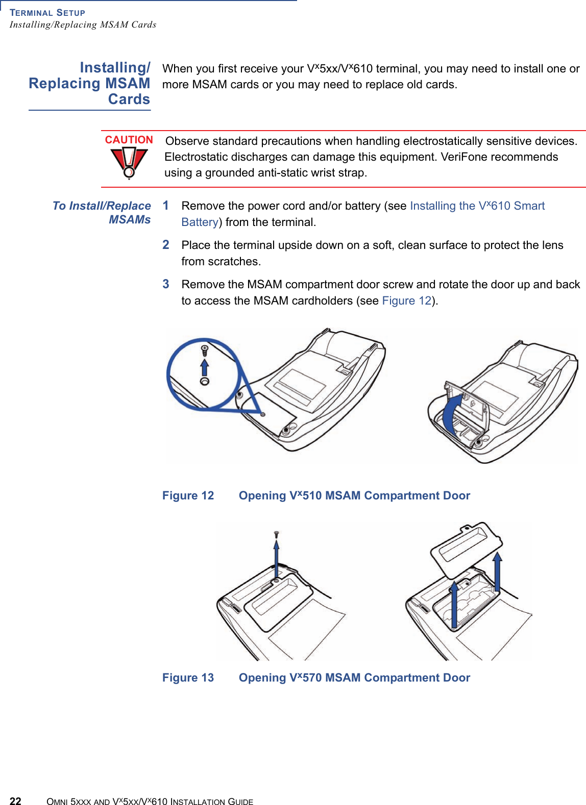
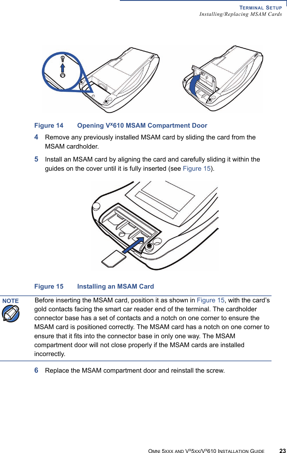
>
VX610C M200 User Manual
USERS MANUAL
Navigation menu
Upload a User Manual
Namespaces
Wiki Guide
HTML
PDF
Info
Views
User Manual
Discussion / Help
Navigation