Verifone VX670WIFI VX670 WiFi Point of Sale Terminal User Manual 24003 book
VeriFone Inc VX670 WiFi Point of Sale Terminal 24003 book
UserManual.wiki
>
Verifone
>
VX670WIFI User Manual
>
Installation Guide
Contents
1.
Installation Guide
2.
Users Manual
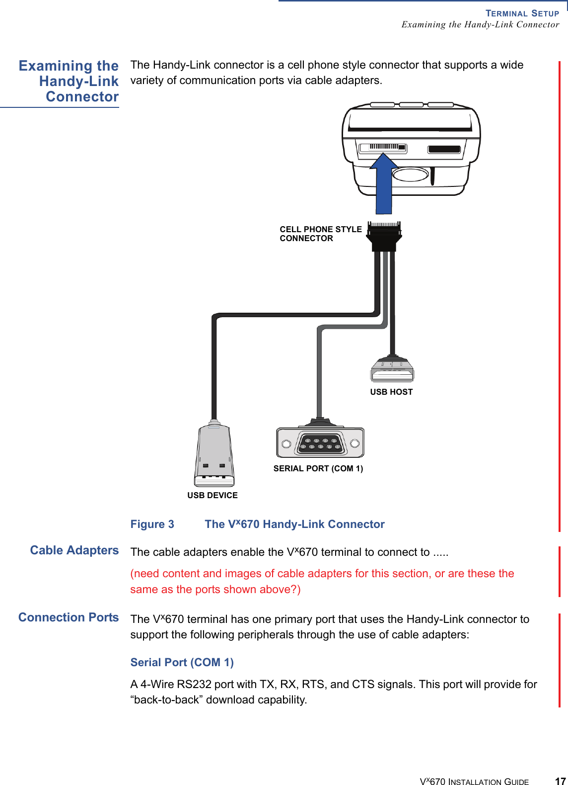
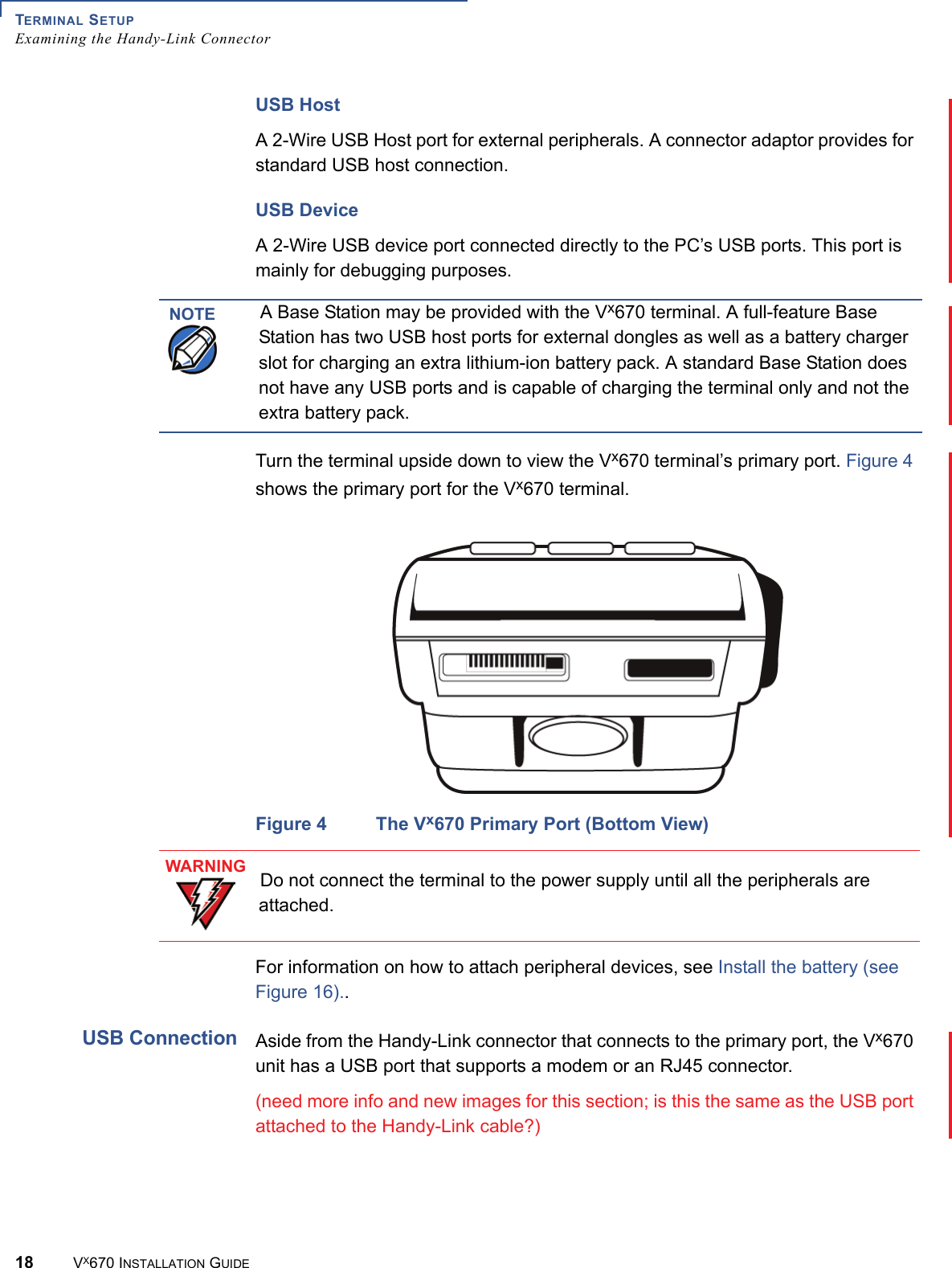
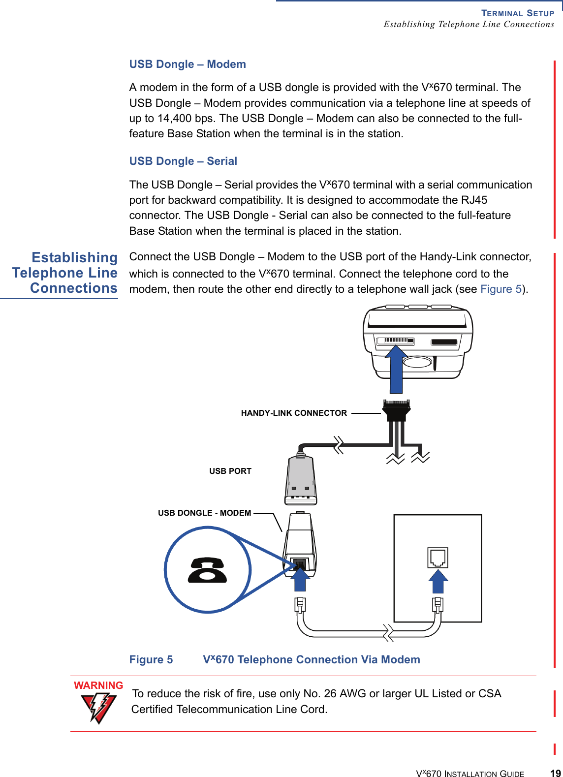
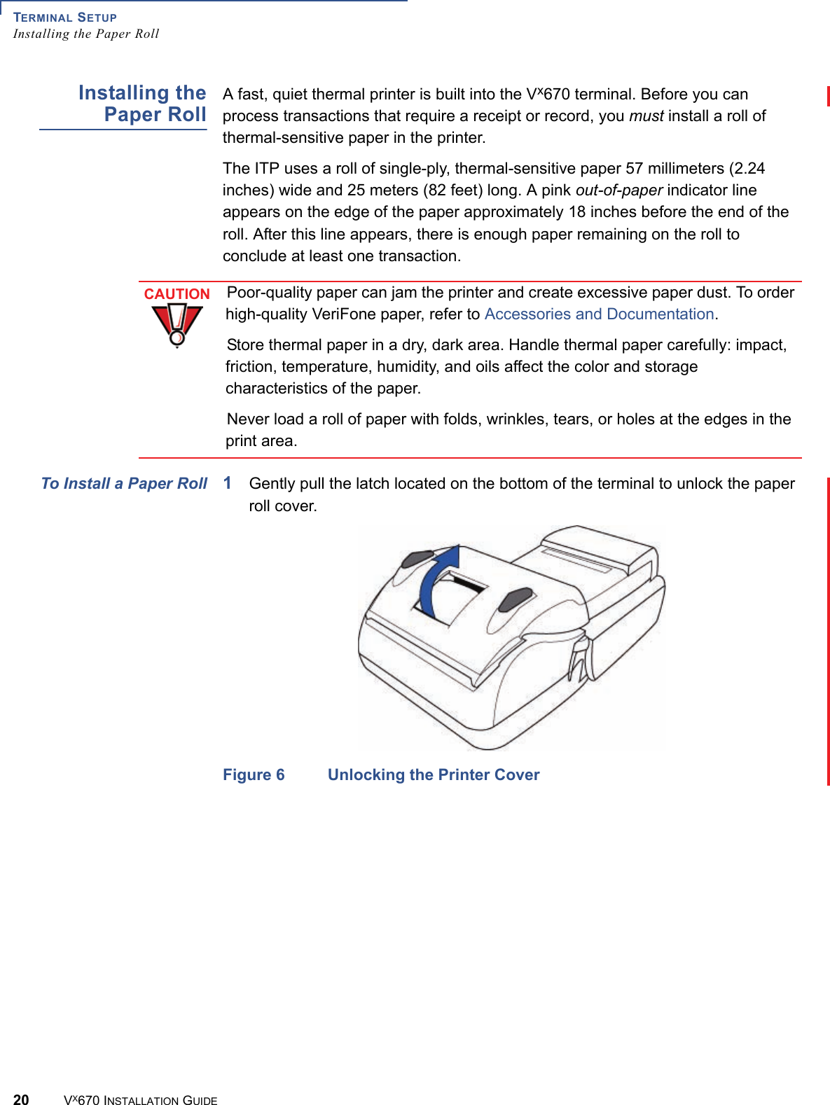
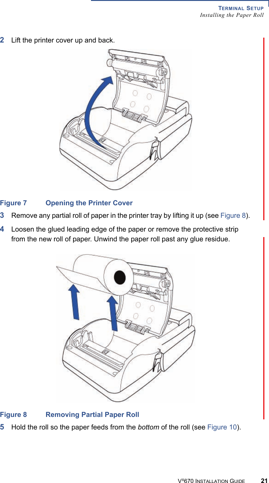
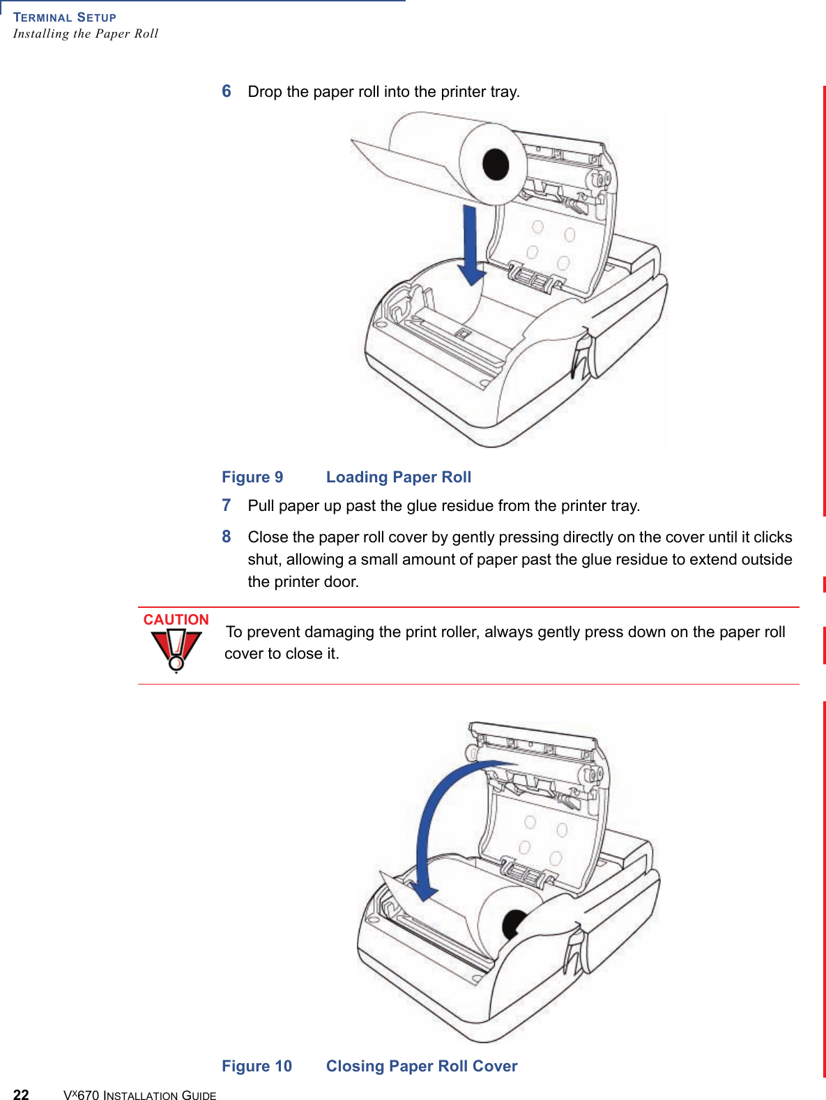
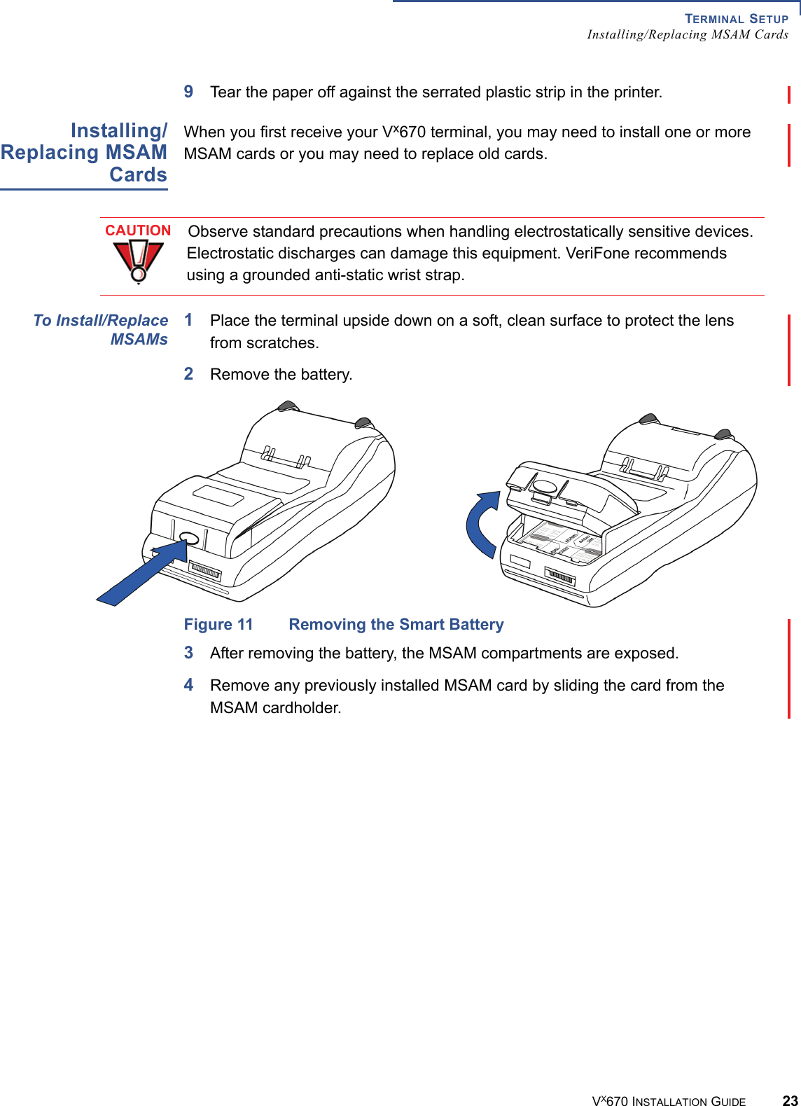
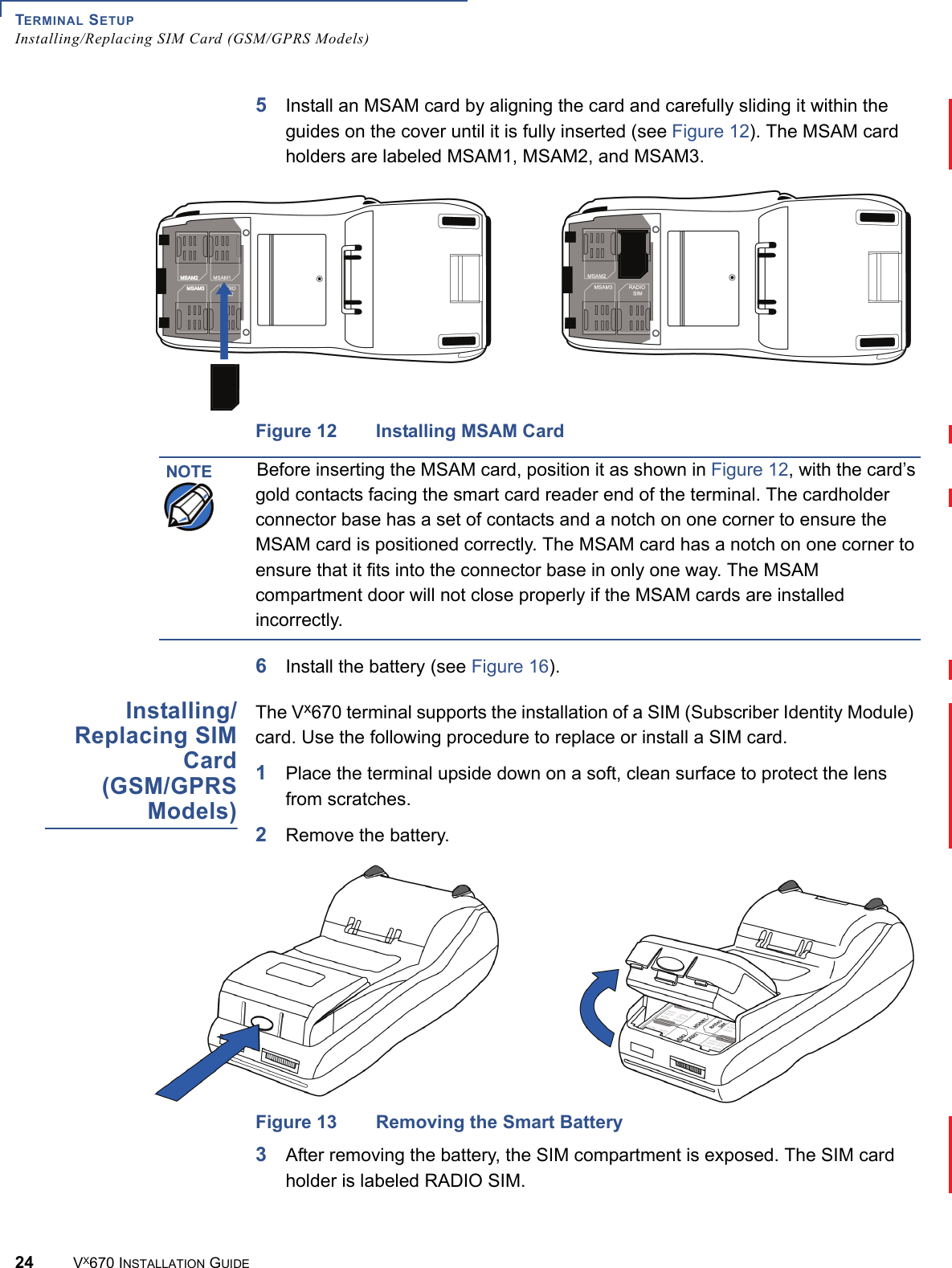
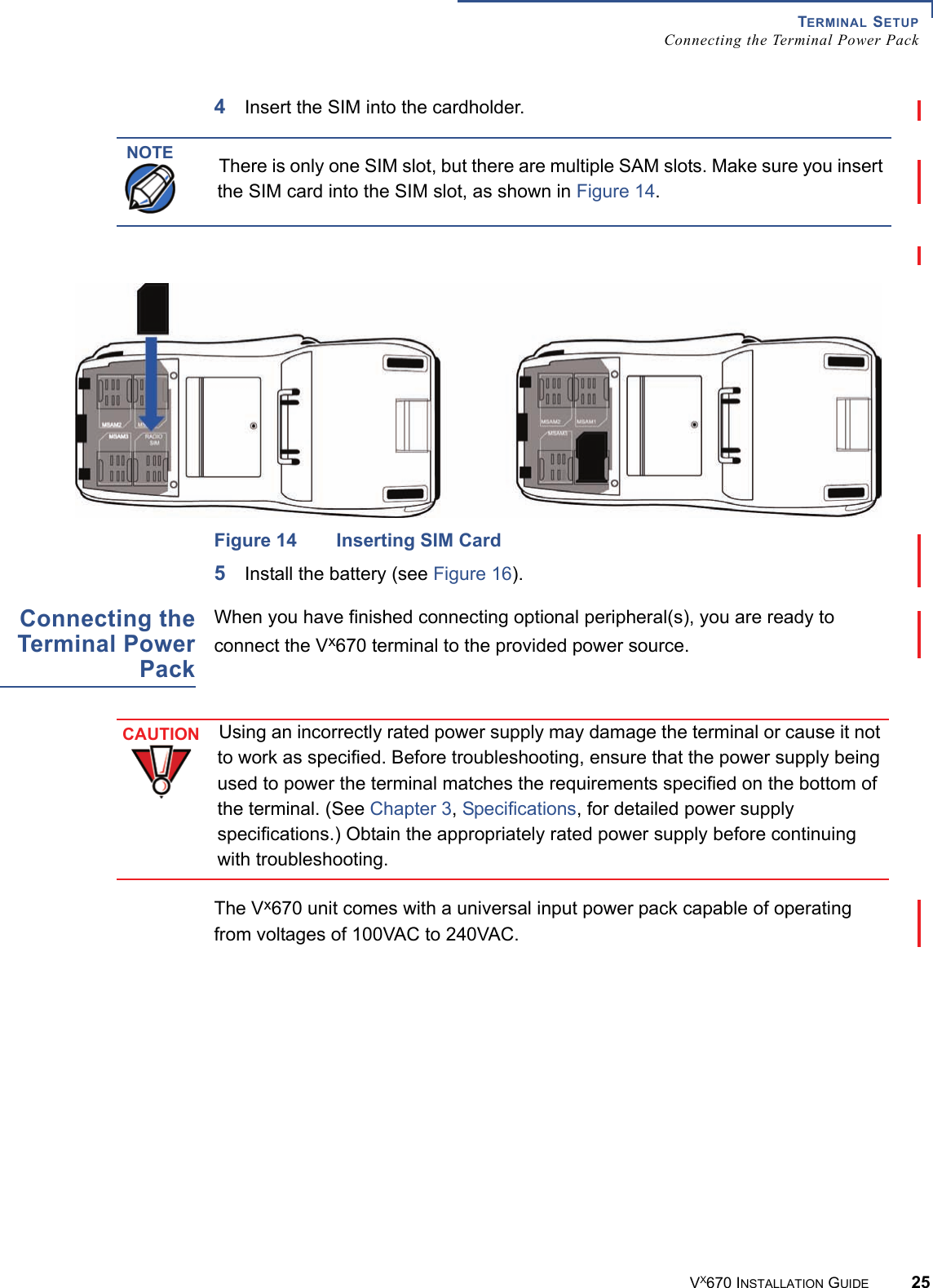
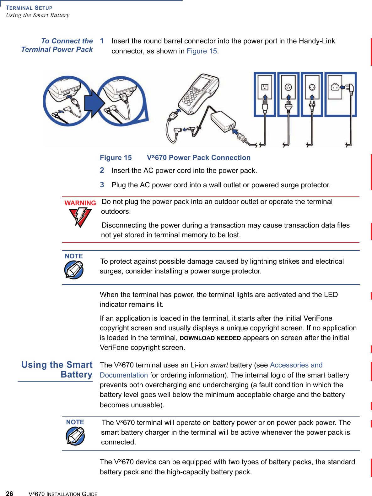
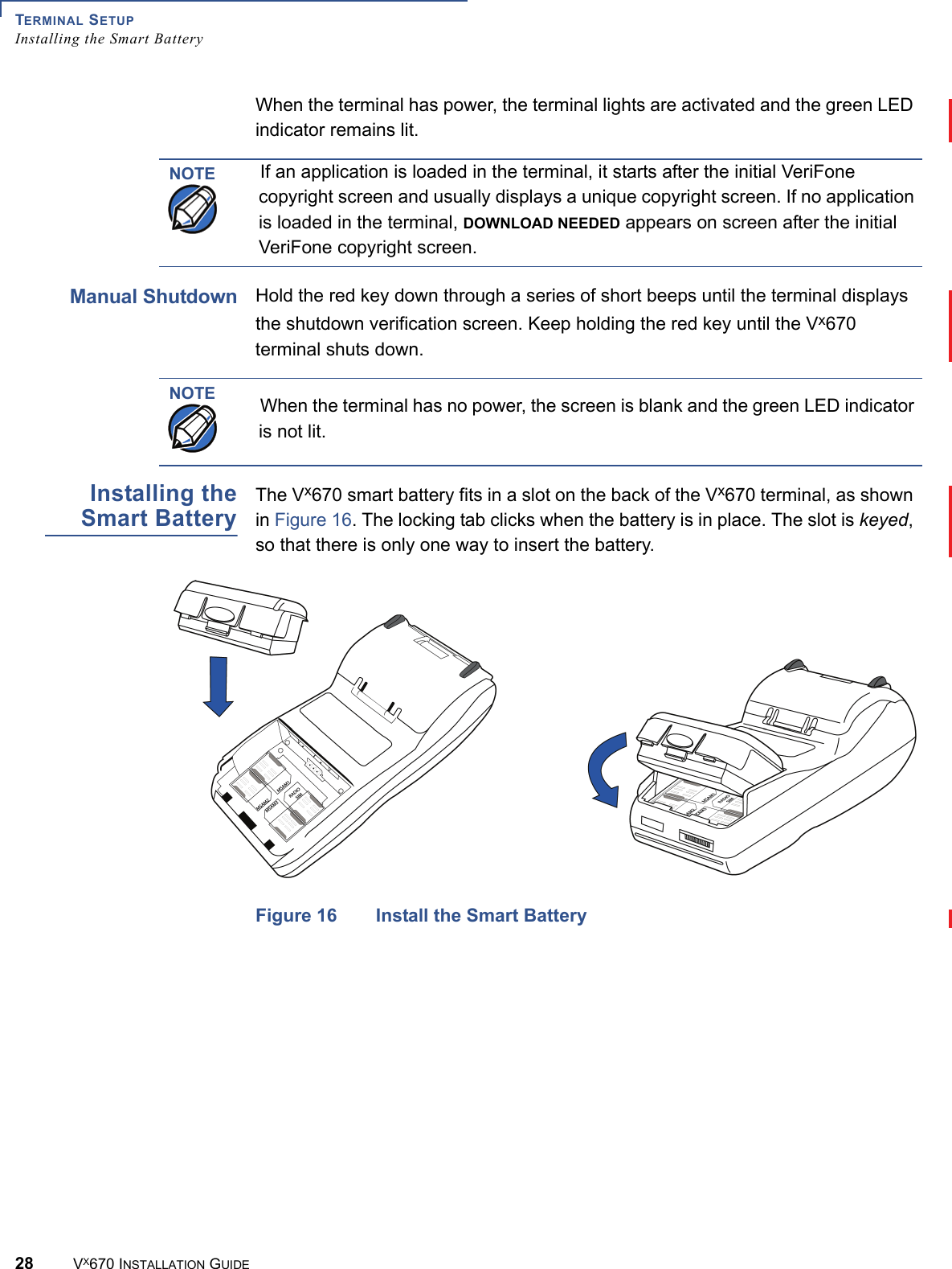
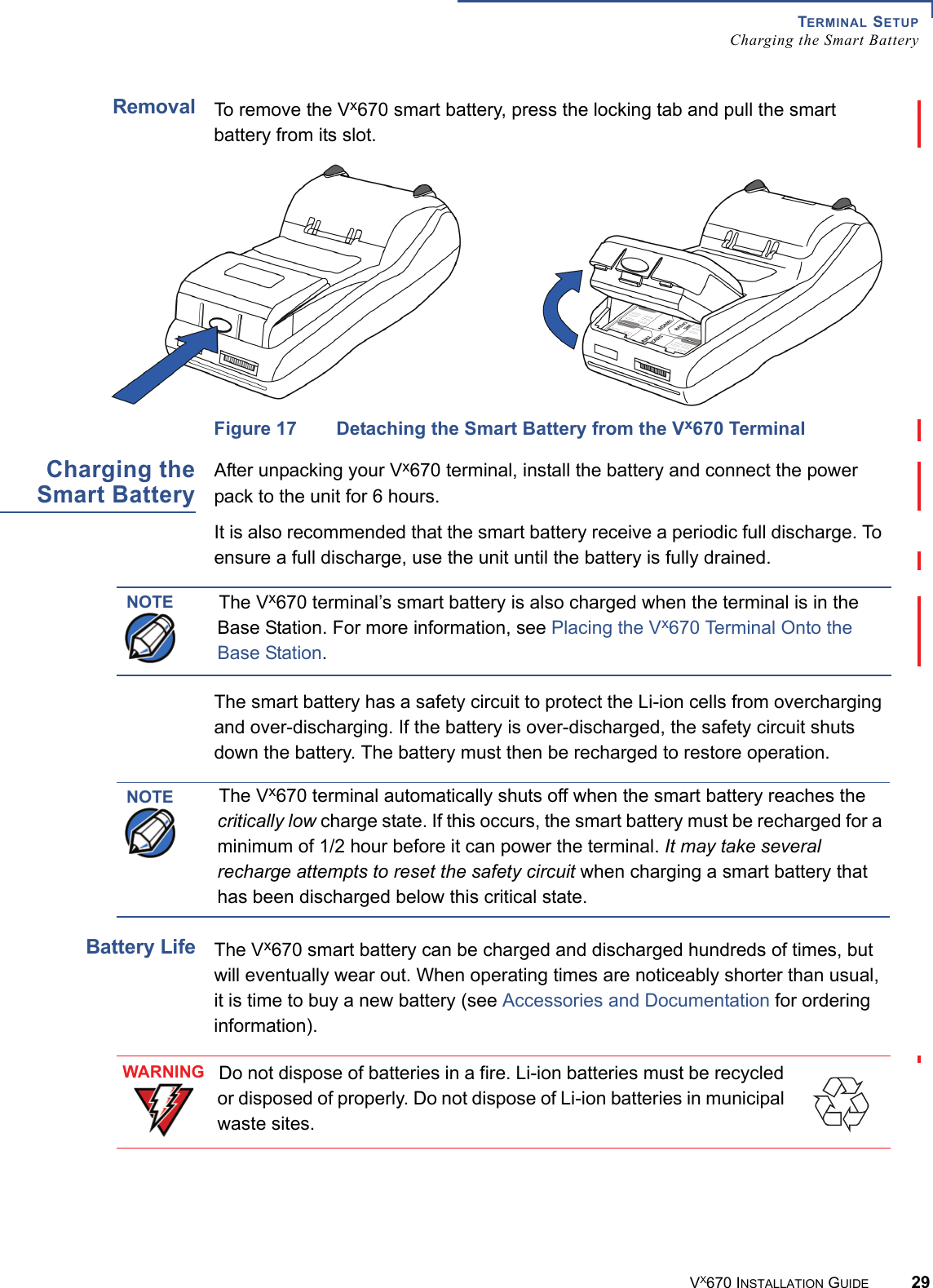
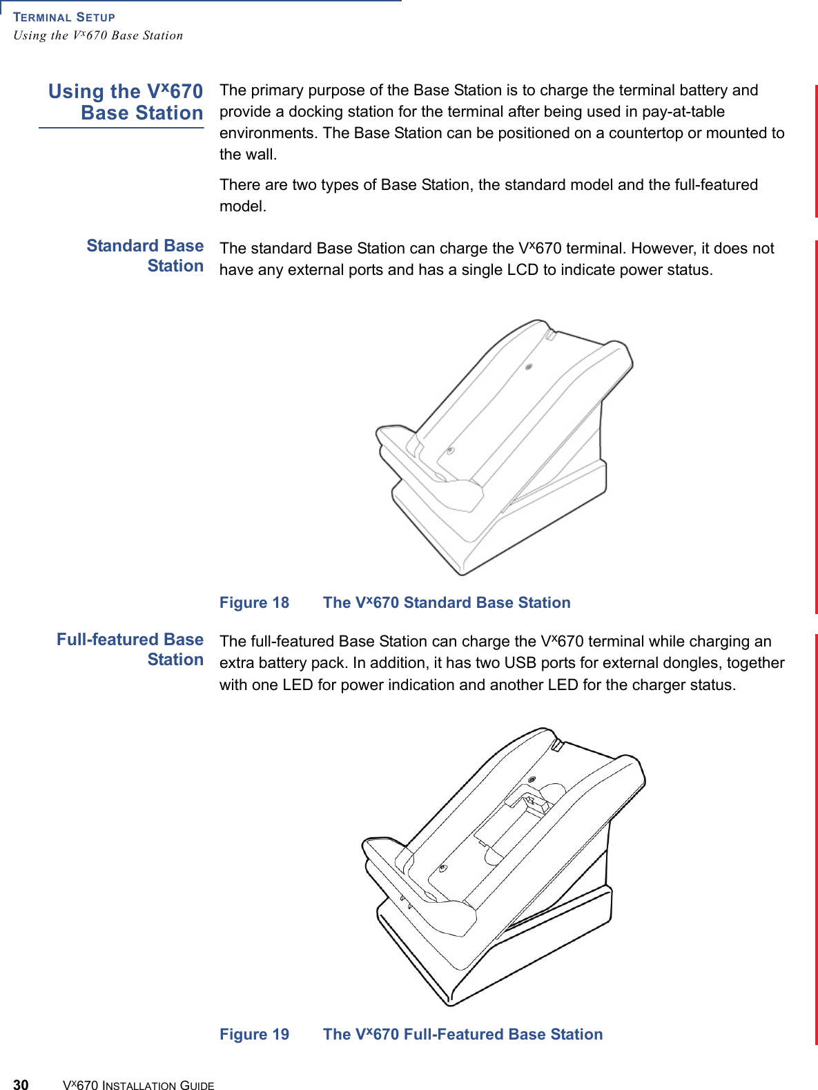
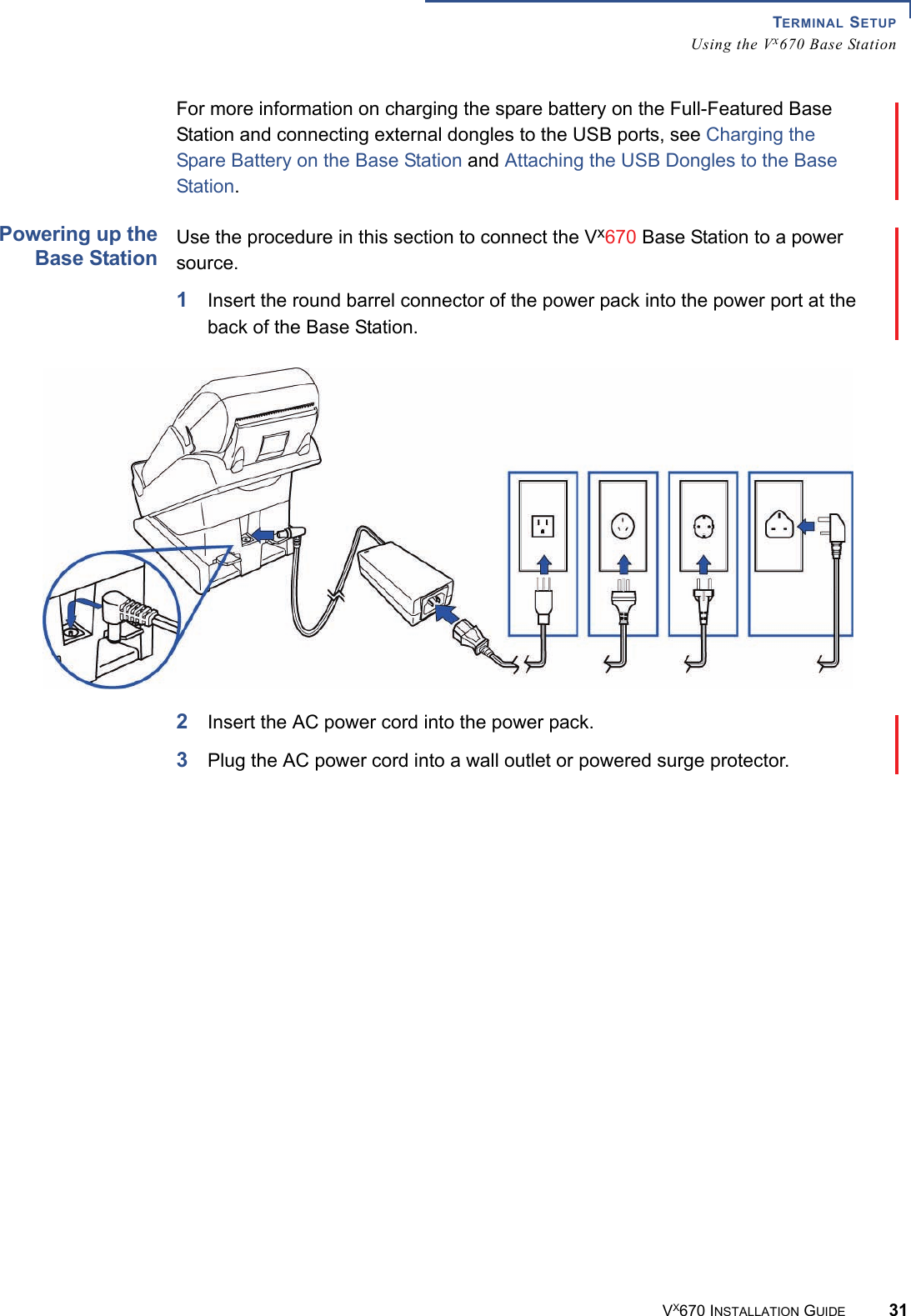
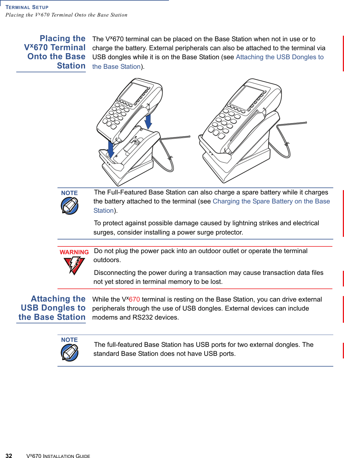
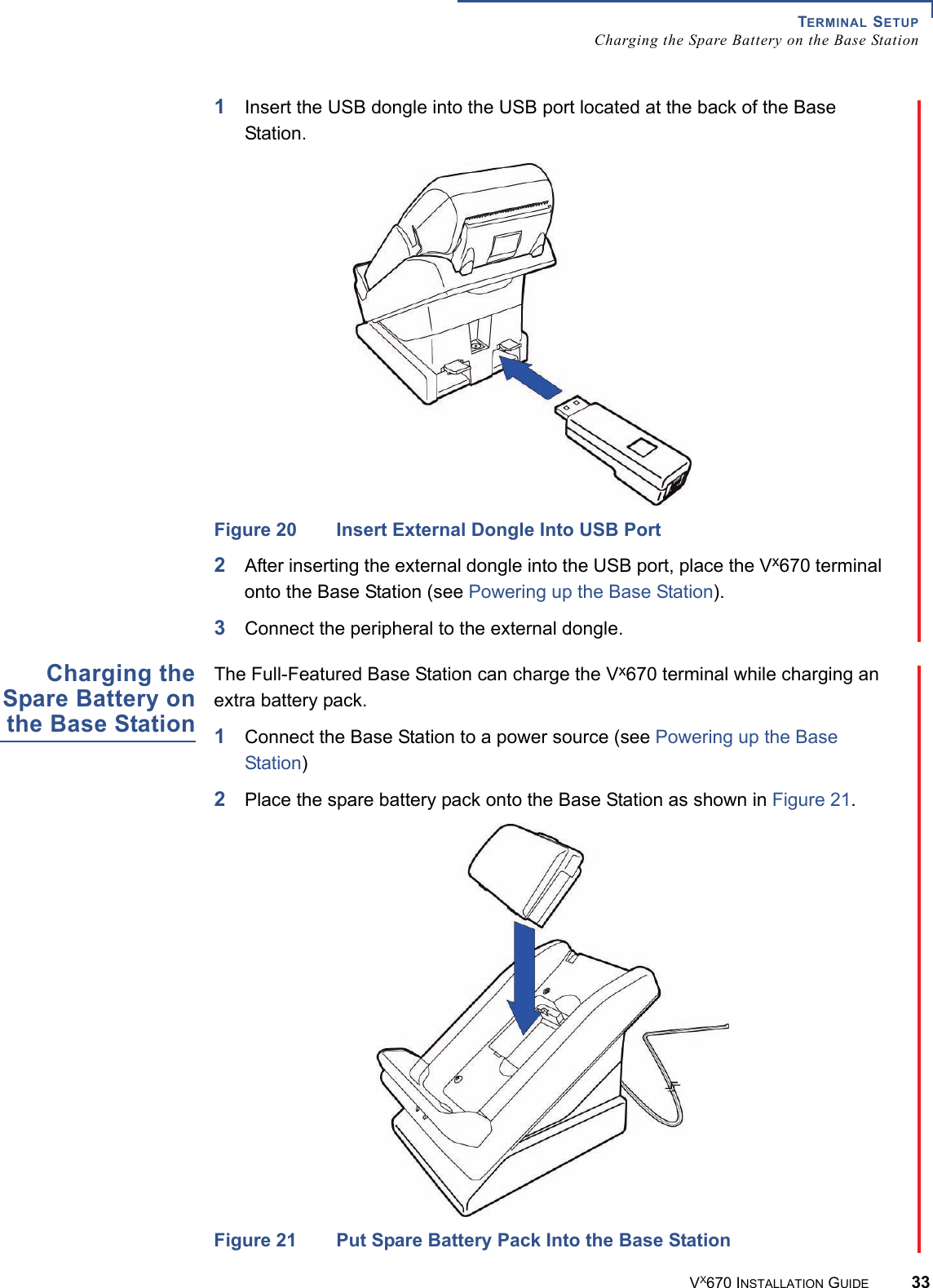
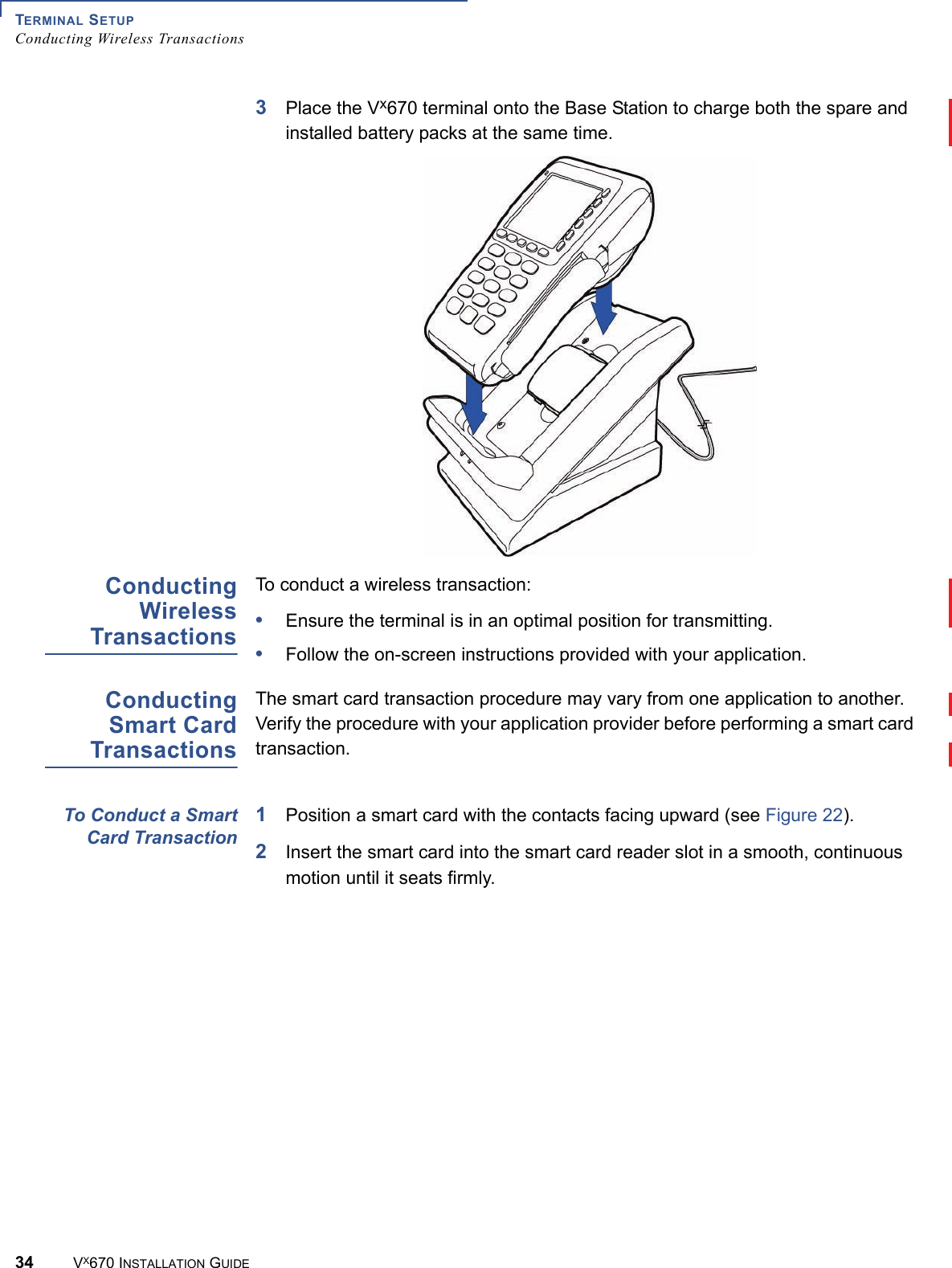
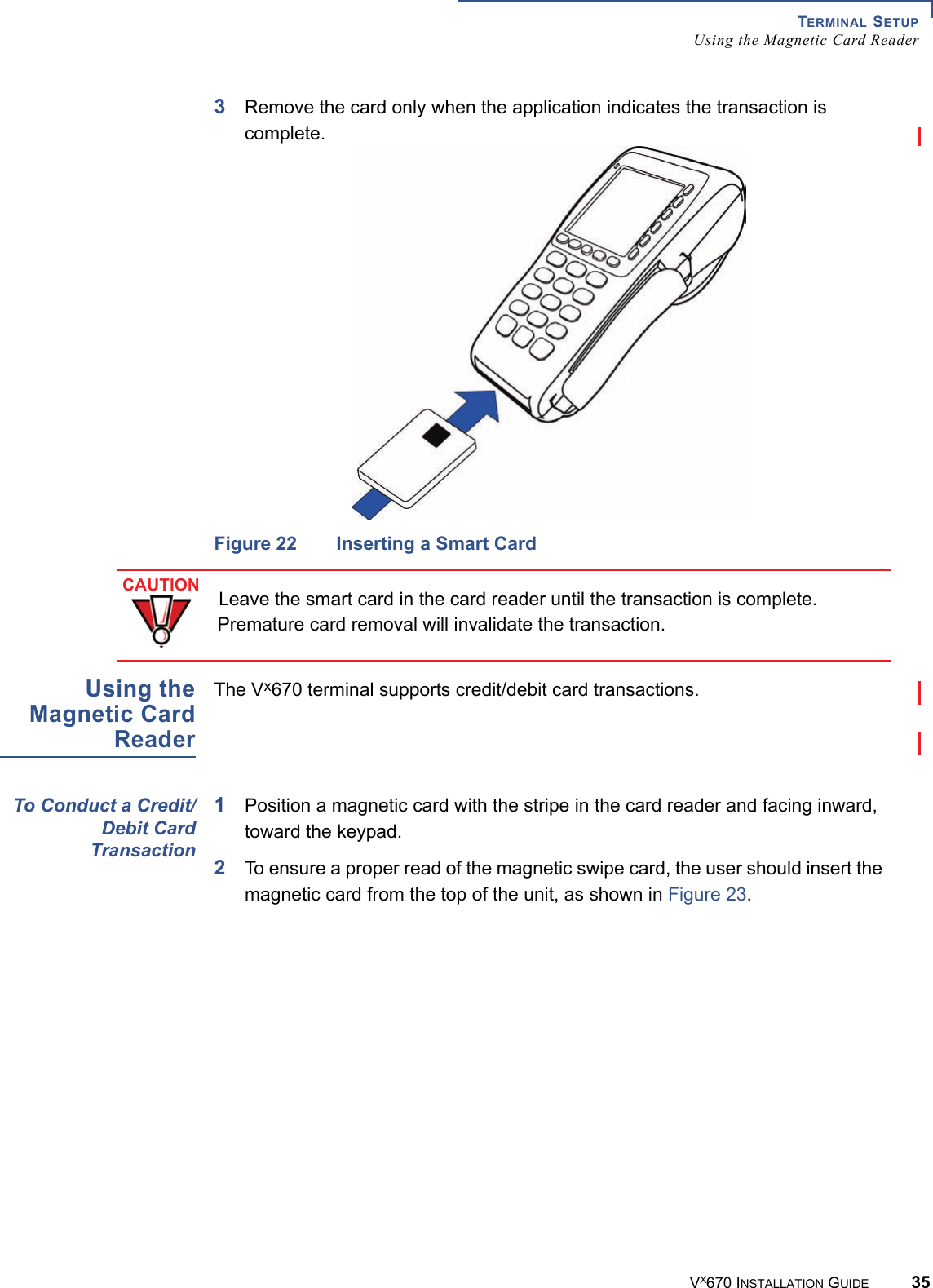
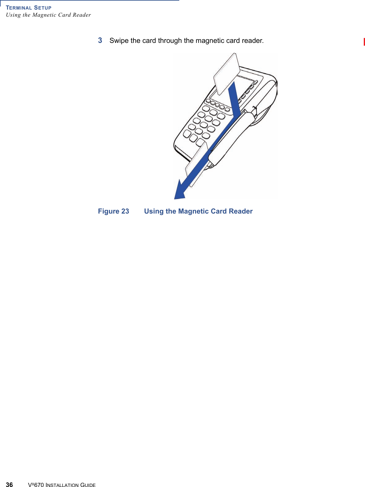
Installation Guide
Navigation menu
Upload a User Manual
Namespaces
Wiki Guide
HTML
PDF
Info
Views
User Manual
Discussion / Help
Navigation