Verifone VX685GC Point of Sales Terminal User Manual VX 685 VX 690 Installation Guide
VeriFone Inc Point of Sales Terminal VX 685 VX 690 Installation Guide
Verifone >
Contents
- 1. User Manual
- 2. User Manual Regulatory
- 3. User Manual Regulation
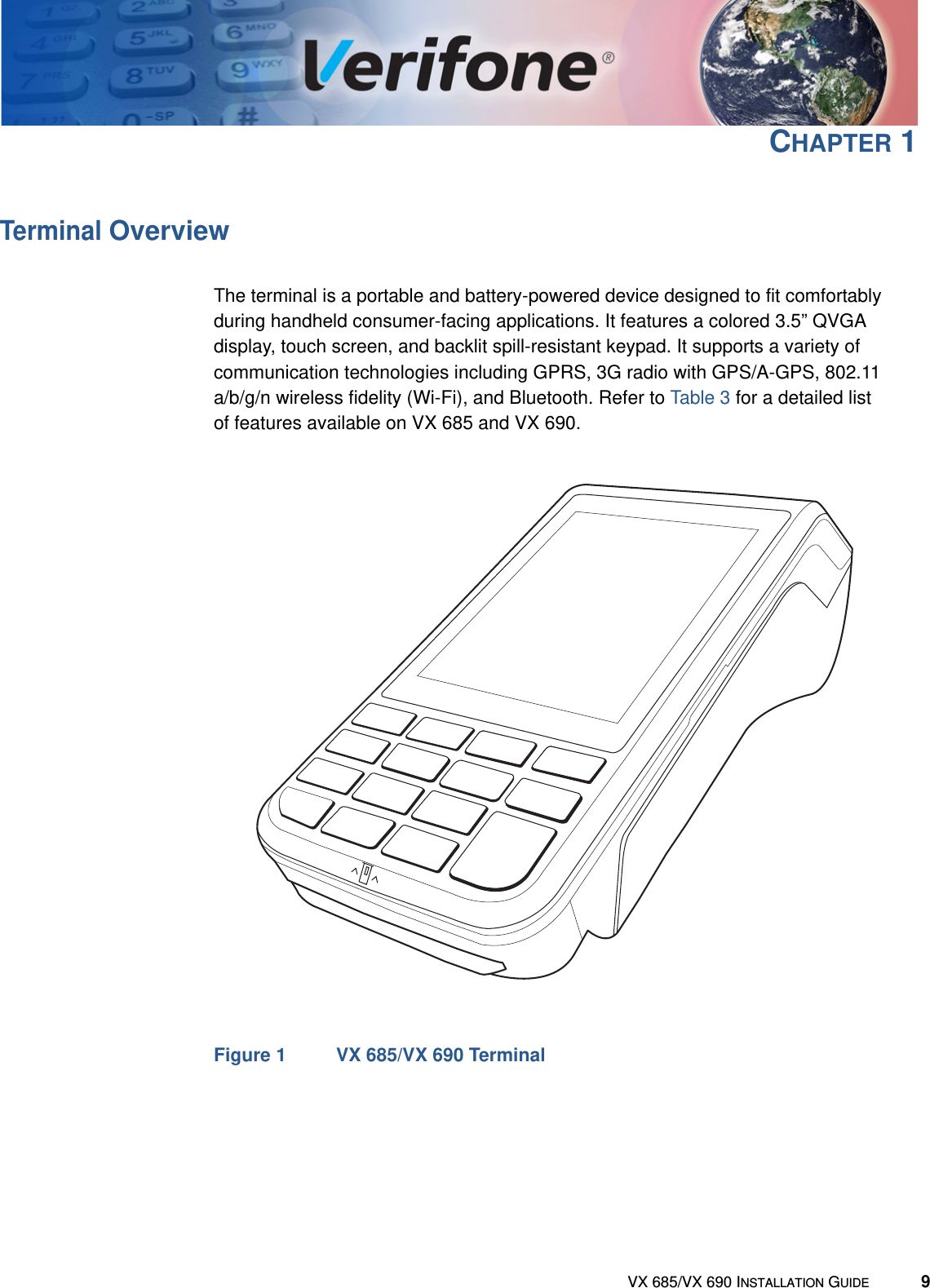
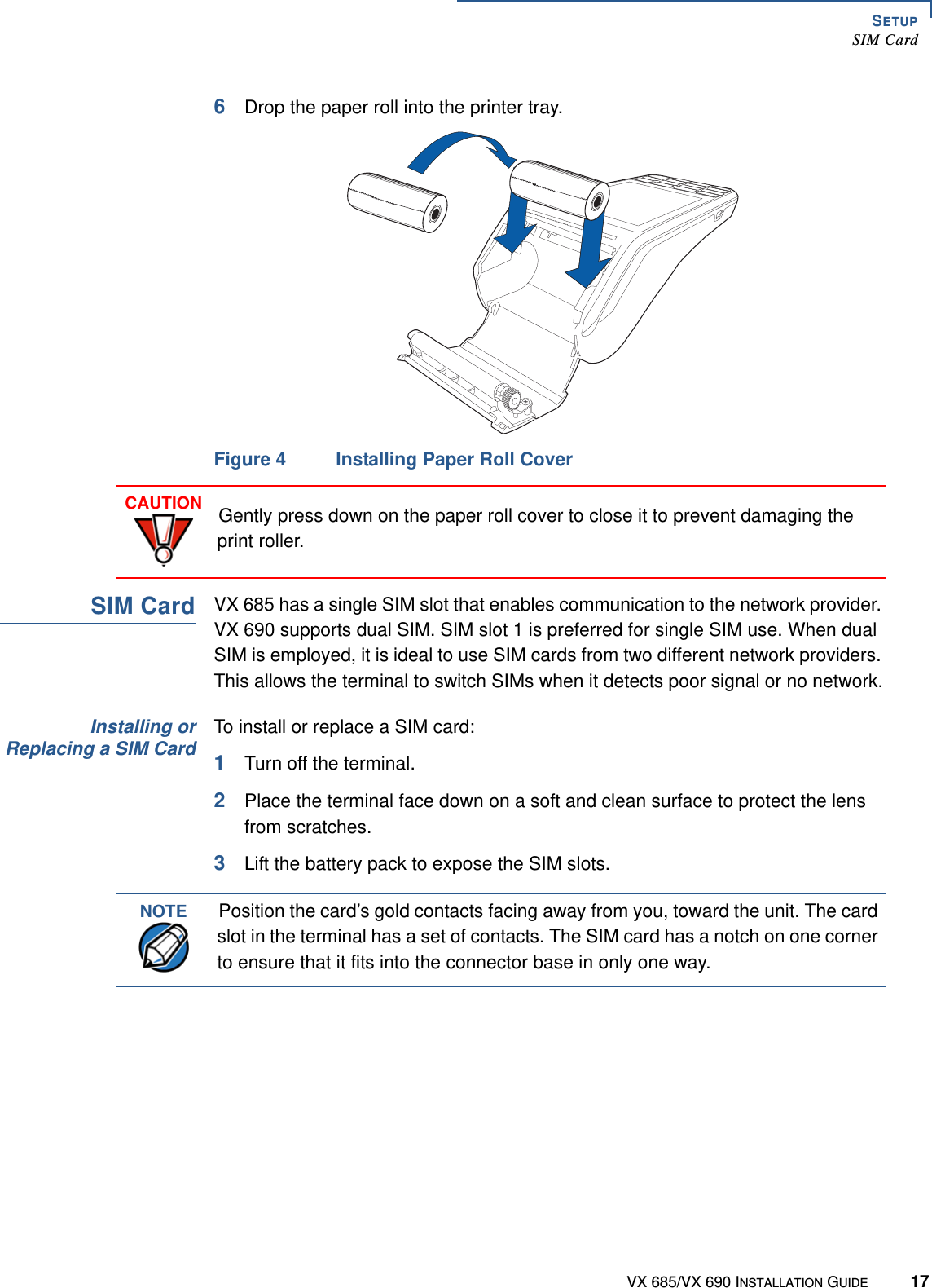
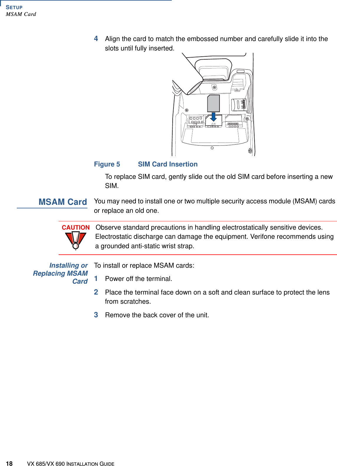
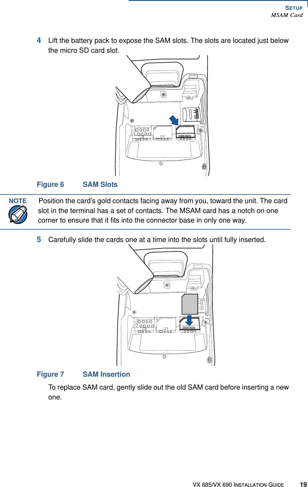
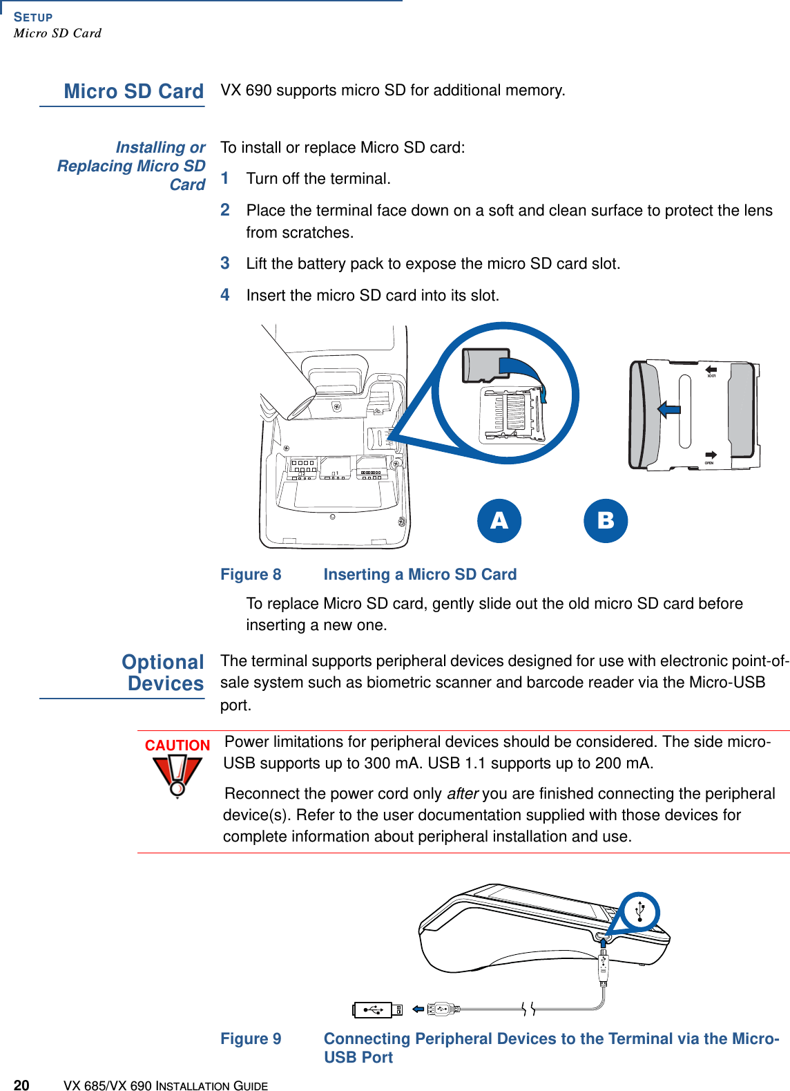
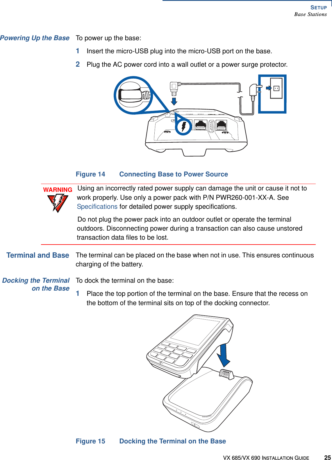
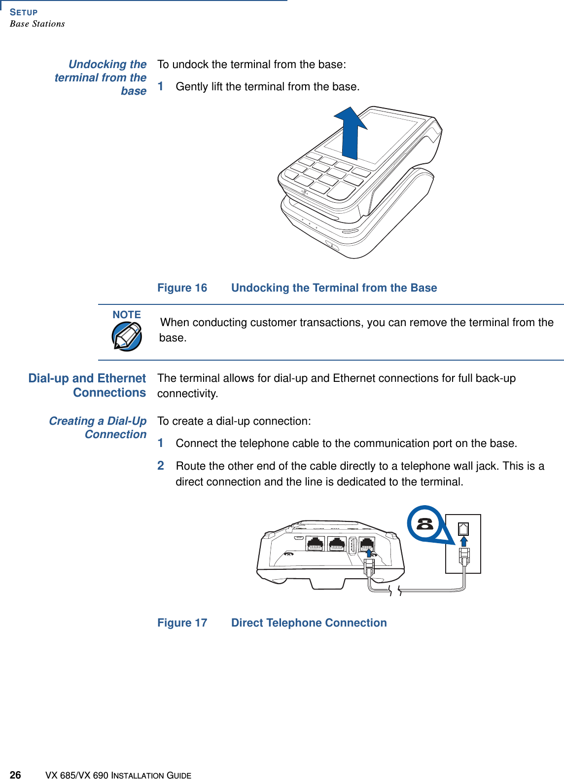
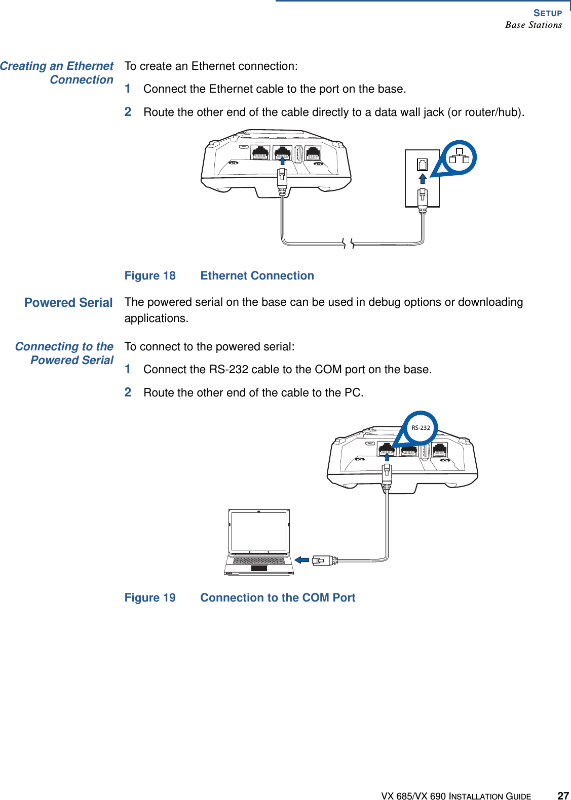
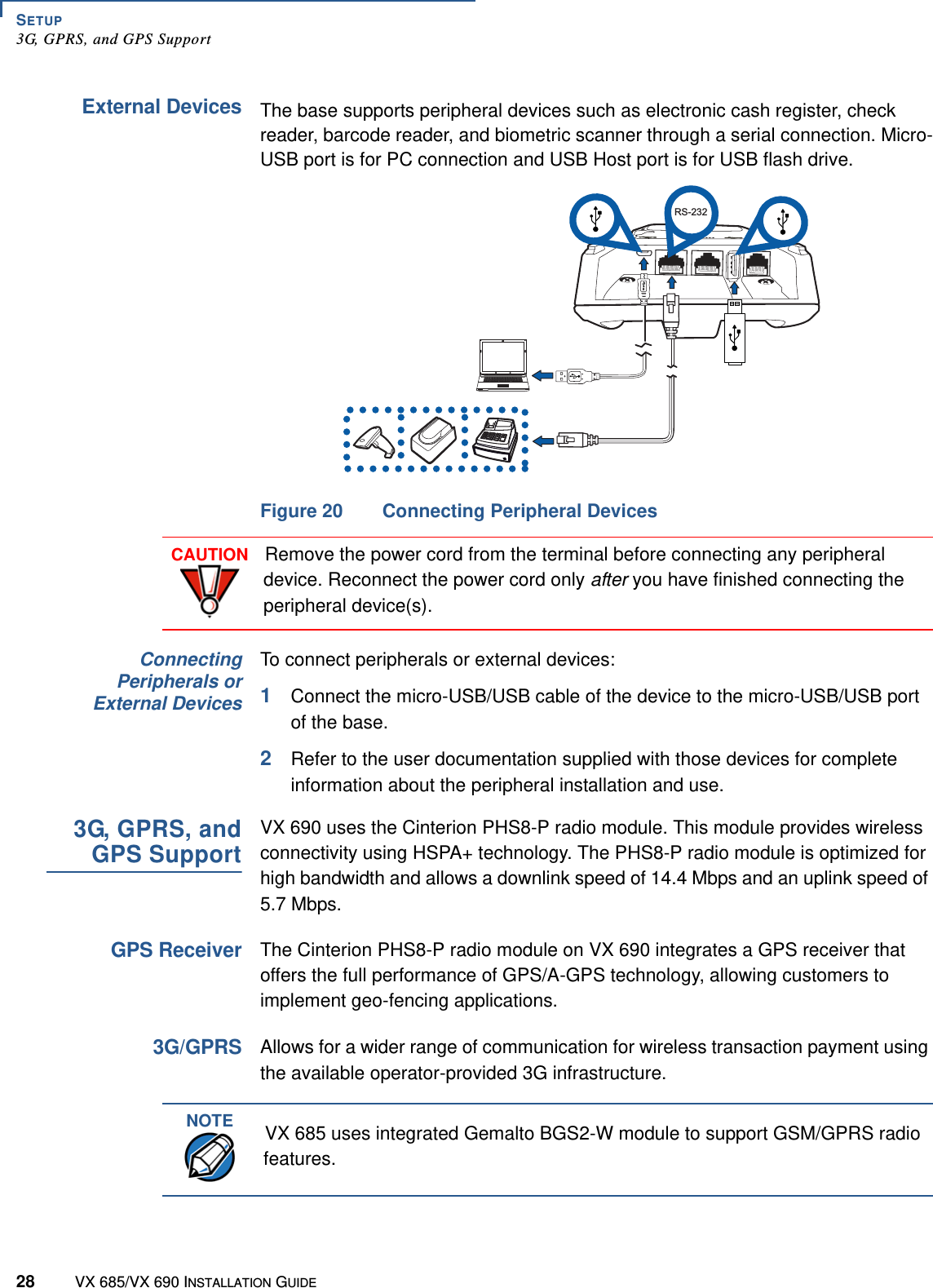
User Manual