Verifone VX685GC Point of Sales Terminal User Manual VX 685 VX 690 Installation Guide
VeriFone Inc Point of Sales Terminal VX 685 VX 690 Installation Guide
Verifone >
Contents
- 1. User Manual
- 2. User Manual Regulatory
- 3. User Manual Regulation
User Manual
Verifone Part Number DOC260-003-EN-C, Revision C
VX 685/VX 690
Installation Guide
All rights reserved. No part of the contents of this document may be reproduced or transmitted in any form without the written
permission of Verifone, Inc.
The information contained in this document is subject to change without notice. Although Verifone has attempted to ensure the
accuracy of the contents of this document, this document may include errors or omissions. The examples and sample programs are
for illustration only and may not be suited for your purpose. You should verify the applicability of any example or sample program
before placing the software into productive use. This document, including without limitation the examples and software programs, is
supplied “As-Is.”
Verifone, Inc.
2099 Gateway Place, Suite 600
San Jose, CA, 95110 USA
www.verifone.com
Verifone Part Number DOC260-003-EN-C, Revision C
VX 685/VX 690 Installation Guide
© 2015 Verifone, Inc.
Verifone, the Verifone logo, VeriCentre, and Verix are registered trademarks of Verifone. Other brand names or
trademarks associated with Verifone’s products and services are trademarks of Verifone, Inc.
All other brand names and trademarks appearing in this manual are the property of their respective holders.
Comments? Please e-mail all comments in this document to your local Verifone Support Team.

VX 685/VX 690 INSTALLATION GUIDE 3
CONTENTS
PREFACE . . . . . . . . . . . . . . . . . . . . . . . . . . . . . . . . . . . . . . . 5
Audience. . . . . . . . . . . . . . . . . . . . . . . . . . . . . . . . . . . . . . . . . . . . . . . . . . . . . . . . 5
Organization . . . . . . . . . . . . . . . . . . . . . . . . . . . . . . . . . . . . . . . . . . . . . . . . . . . . . 5
Related Documentation . . . . . . . . . . . . . . . . . . . . . . . . . . . . . . . . . . . . . . . . . . . . 5
Guide Conventions. . . . . . . . . . . . . . . . . . . . . . . . . . . . . . . . . . . . . . . . . . . . . . . . 6
Acronym Definitions . . . . . . . . . . . . . . . . . . . . . . . . . . . . . . . . . . . . . . . . . . . . 7
CHAPTER 1
Terminal Overview Features and Benefits . . . . . . . . . . . . . . . . . . . . . . . . . . . . . . . . . . . . . . . . . . . . 10
Exceptional Ease of Use. . . . . . . . . . . . . . . . . . . . . . . . . . . . . . . . . . . . . . . . 10
Performance and Durability . . . . . . . . . . . . . . . . . . . . . . . . . . . . . . . . . . . . . 10
Security . . . . . . . . . . . . . . . . . . . . . . . . . . . . . . . . . . . . . . . . . . . . . . . . . . . . . 10
Contactless Capability . . . . . . . . . . . . . . . . . . . . . . . . . . . . . . . . . . . . . . . . . 11
Communication Technology . . . . . . . . . . . . . . . . . . . . . . . . . . . . . . . . . . . . . 11
Differences Between VX 685 and VX 690 Terminals. . . . . . . . . . . . . . . . . . . . . 11
CHAPTER 2
Setup Terminal Location. . . . . . . . . . . . . . . . . . . . . . . . . . . . . . . . . . . . . . . . . . . . . . . . 13
Ease of Use . . . . . . . . . . . . . . . . . . . . . . . . . . . . . . . . . . . . . . . . . . . . . . . . . 13
Environmental Factors . . . . . . . . . . . . . . . . . . . . . . . . . . . . . . . . . . . . . . . . . 13
Electrical Considerations . . . . . . . . . . . . . . . . . . . . . . . . . . . . . . . . . . . . . . . 14
Inside the Shipping Carton . . . . . . . . . . . . . . . . . . . . . . . . . . . . . . . . . . . . . . . . . 14
Terminal Features . . . . . . . . . . . . . . . . . . . . . . . . . . . . . . . . . . . . . . . . . . . . . . . 15
Front Panel . . . . . . . . . . . . . . . . . . . . . . . . . . . . . . . . . . . . . . . . . . . . . . . . . . 15
Connection Port . . . . . . . . . . . . . . . . . . . . . . . . . . . . . . . . . . . . . . . . . . . . . . . . . 16
Paper Roll. . . . . . . . . . . . . . . . . . . . . . . . . . . . . . . . . . . . . . . . . . . . . . . . . . . . . . 16
SIM Card . . . . . . . . . . . . . . . . . . . . . . . . . . . . . . . . . . . . . . . . . . . . . . . . . . . . . . 17
MSAM Card . . . . . . . . . . . . . . . . . . . . . . . . . . . . . . . . . . . . . . . . . . . . . . . . . . . . 18
Micro SD Card . . . . . . . . . . . . . . . . . . . . . . . . . . . . . . . . . . . . . . . . . . . . . . . . . . 20
Optional Devices . . . . . . . . . . . . . . . . . . . . . . . . . . . . . . . . . . . . . . . . . . . . . . . . 20
Battery Features. . . . . . . . . . . . . . . . . . . . . . . . . . . . . . . . . . . . . . . . . . . . . . . . . 21
Battery Life . . . . . . . . . . . . . . . . . . . . . . . . . . . . . . . . . . . . . . . . . . . . . . . . . . 21
Battery Behavior . . . . . . . . . . . . . . . . . . . . . . . . . . . . . . . . . . . . . . . . . . . . . . 21
Terminal Power Source . . . . . . . . . . . . . . . . . . . . . . . . . . . . . . . . . . . . . . . . . . . 22
Base Stations . . . . . . . . . . . . . . . . . . . . . . . . . . . . . . . . . . . . . . . . . . . . . . . . . . . 24
Charging Base . . . . . . . . . . . . . . . . . . . . . . . . . . . . . . . . . . . . . . . . . . . . . . . 24
BT Base . . . . . . . . . . . . . . . . . . . . . . . . . . . . . . . . . . . . . . . . . . . . . . . . . . . . 24
Terminal and Base . . . . . . . . . . . . . . . . . . . . . . . . . . . . . . . . . . . . . . . . . . . . 25
Dial-up and Ethernet Connections . . . . . . . . . . . . . . . . . . . . . . . . . . . . . . . . 26
Powered Serial . . . . . . . . . . . . . . . . . . . . . . . . . . . . . . . . . . . . . . . . . . . . . . . 27
External Devices . . . . . . . . . . . . . . . . . . . . . . . . . . . . . . . . . . . . . . . . . . . . . . 28
3G, GPRS, and GPS Support . . . . . . . . . . . . . . . . . . . . . . . . . . . . . . . . . . . . . . 28
GPS Receiver . . . . . . . . . . . . . . . . . . . . . . . . . . . . . . . . . . . . . . . . . . . . . . . . 28
3G/GPRS . . . . . . . . . . . . . . . . . . . . . . . . . . . . . . . . . . . . . . . . . . . . . . . . . . . 28
VX 690 BT/Wi-Fi Support . . . . . . . . . . . . . . . . . . . . . . . . . . . . . . . . . . . . . . . . . . 29
Bluetooth Support . . . . . . . . . . . . . . . . . . . . . . . . . . . . . . . . . . . . . . . . . . . . . 29

4VX 685/VX 690 INSTALLATION GUIDE
Wireless Transaction . . . . . . . . . . . . . . . . . . . . . . . . . . . . . . . . . . . . . . . . . . 34
Smart Card Reader . . . . . . . . . . . . . . . . . . . . . . . . . . . . . . . . . . . . . . . . . . . . . . 34
Magnetic Card Reader . . . . . . . . . . . . . . . . . . . . . . . . . . . . . . . . . . . . . . . . . . . . 35
Contactless Smart Card Transaction . . . . . . . . . . . . . . . . . . . . . . . . . . . . . . . . . 35
CHAPTER 3
Specifications Power Rating . . . . . . . . . . . . . . . . . . . . . . . . . . . . . . . . . . . . . . . . . . . . . . . . . . . 37
Power Pack . . . . . . . . . . . . . . . . . . . . . . . . . . . . . . . . . . . . . . . . . . . . . . . . . . . . 37
Temperature . . . . . . . . . . . . . . . . . . . . . . . . . . . . . . . . . . . . . . . . . . . . . . . . . . . . 37
External Dimensions. . . . . . . . . . . . . . . . . . . . . . . . . . . . . . . . . . . . . . . . . . . . . . 37
Weight . . . . . . . . . . . . . . . . . . . . . . . . . . . . . . . . . . . . . . . . . . . . . . . . . . . . . . . . 37
Processor . . . . . . . . . . . . . . . . . . . . . . . . . . . . . . . . . . . . . . . . . . . . . . . . . . . . . . 37
Memory. . . . . . . . . . . . . . . . . . . . . . . . . . . . . . . . . . . . . . . . . . . . . . . . . . . . . . . . 37
Display . . . . . . . . . . . . . . . . . . . . . . . . . . . . . . . . . . . . . . . . . . . . . . . . . . . . . . . . 37
Magnetic Card Reader . . . . . . . . . . . . . . . . . . . . . . . . . . . . . . . . . . . . . . . . . . . . 37
Primary Smart Card . . . . . . . . . . . . . . . . . . . . . . . . . . . . . . . . . . . . . . . . . . . . . . 37
SAM Card Reader . . . . . . . . . . . . . . . . . . . . . . . . . . . . . . . . . . . . . . . . . . . . . . . 38
Keypad . . . . . . . . . . . . . . . . . . . . . . . . . . . . . . . . . . . . . . . . . . . . . . . . . . . . . . . . 38
Peripheral Ports . . . . . . . . . . . . . . . . . . . . . . . . . . . . . . . . . . . . . . . . . . . . . . . . . 38
Security. . . . . . . . . . . . . . . . . . . . . . . . . . . . . . . . . . . . . . . . . . . . . . . . . . . . . . . . 38
CHAPTER 4
Maintenance and
Cleaning
Additional Safety Information . . . . . . . . . . . . . . . . . . . . . . . . . . . . . . . . . . . . . . . 40
Power Adapter . . . . . . . . . . . . . . . . . . . . . . . . . . . . . . . . . . . . . . . . . . . . . . . 40
Potentially Explosive Environments . . . . . . . . . . . . . . . . . . . . . . . . . . . . . . . 40
Card Readers . . . . . . . . . . . . . . . . . . . . . . . . . . . . . . . . . . . . . . . . . . . . . . . . 40
CHAPTER 5
Service and Support Service Returns . . . . . . . . . . . . . . . . . . . . . . . . . . . . . . . . . . . . . . . . . . . . . . . . . 41
Accessories and Documentation . . . . . . . . . . . . . . . . . . . . . . . . . . . . . . . . . . . . 42
CHAPTER 6
Troubleshooting
Guidelines
Terminal Does Not Start . . . . . . . . . . . . . . . . . . . . . . . . . . . . . . . . . . . . . . . . . . . 45
Terminal Display Does Not Show Correct/Readable Info. . . . . . . . . . . . . . . . . . 45
Blank Display . . . . . . . . . . . . . . . . . . . . . . . . . . . . . . . . . . . . . . . . . . . . . . . . . . . 46
Printer Does Not Print. . . . . . . . . . . . . . . . . . . . . . . . . . . . . . . . . . . . . . . . . . . . . 46
Printer Paper Jam. . . . . . . . . . . . . . . . . . . . . . . . . . . . . . . . . . . . . . . . . . . . . . . . 46
Keypad Does Not Respond . . . . . . . . . . . . . . . . . . . . . . . . . . . . . . . . . . . . . . . . 47
Transactions Fail To Process . . . . . . . . . . . . . . . . . . . . . . . . . . . . . . . . . . . . . . . 47
APPENDIX A
Battery Information Charging . . . . . . . . . . . . . . . . . . . . . . . . . . . . . . . . . . . . . . . . . . . . . . . . . . . . . . . 49
Advantages . . . . . . . . . . . . . . . . . . . . . . . . . . . . . . . . . . . . . . . . . . . . . . . . . . 49
Precautions . . . . . . . . . . . . . . . . . . . . . . . . . . . . . . . . . . . . . . . . . . . . . . . . . . 50
Notable Battery Specifications . . . . . . . . . . . . . . . . . . . . . . . . . . . . . . . . . . . . . . 51
Safety/Protection Circuit . . . . . . . . . . . . . . . . . . . . . . . . . . . . . . . . . . . . . . . . 51
Cell Temperature Monitoring . . . . . . . . . . . . . . . . . . . . . . . . . . . . . . . . . . . . 51
ESD Protection . . . . . . . . . . . . . . . . . . . . . . . . . . . . . . . . . . . . . . . . . . . . . . . 51
Trip Recovery . . . . . . . . . . . . . . . . . . . . . . . . . . . . . . . . . . . . . . . . . . . . . . . . 51
Battery FAQs . . . . . . . . . . . . . . . . . . . . . . . . . . . . . . . . . . . . . . . . . . . . . . . . . . . 51
Battery Specific Terms and Definitions. . . . . . . . . . . . . . . . . . . . . . . . . . . . . . . . 52
General Battery Terms and Definitions . . . . . . . . . . . . . . . . . . . . . . . . . . . . . . . 52

VX 685/VX 690 INSTALLATION GUIDE 5
PREFACE
This guide is the primary source of information for setting up and installing the
terminal.
Audience
This guide is useful to anyone installing and configuring the terminal.
Organization
This guide is organized as follows:
Chapter 1, Terminal Overview. Provides an overview of the terminal.
Chapter 2, Setup. Explains setup and installation of the terminal, selecting a
location, and establishing connections with other devices.
Chapter 3, Specifications. Discusses power requirements and dimensions of the
terminal.
Chapter 4, Maintenance and Cleaning. Explains maintenance of the terminal.
Chapter 5, Service and Support. Provides information on contacting your Verifone
service provider and information on how to order accessories or documentations
from Verifone.
Chapter 6, Troubleshooting Guidelines. Provides troubleshooting guidelines
should you encounter a problem in terminal installation and configuration.
Appendix A, Battery Information. Provides information about the battery.
Related
Documentation
Refer to the following set of documents to learn more about the terminal:
VX 690 Certifications and Regulations Sheet VPN - DOC260-001-EN
VX 690 Quick Installation Guide VPN - DOC260-002-EN
VX 685/VX 690 Reference Guide VPN - DOC260-004-EN
VX 690 Charging Base Certifications and
Regulations Sheet
VPN - DOC260-005-EN
VX 690 BT Base Certifications and Regulations
Sheet
VPN - DOC260-006-EN
VX 685/VX 690 Charging Base Quick Installation
Guide
VPN - DOC260-007-EN
VX 690 BT Base Quick Installation Guide VPN - DOC260-008-EN
VX 690 3G-BT-WiFi Certifications and Regulations
Sheet
VPN - DOC260-009-EN
VX 690 3G-BT-WiFi Quick Installation Guide VPN - DOC260-010-EN
VX 685 Certifications and Regulations Sheet VPN - DOC262-001-EN

PREFACE
Guide Conventions
6VX 685/VX 690 INSTALLATION GUIDE
Guide
Conventions
Various conventions are used to help you quickly identify special formatting.
Table 1 describes these conventions and provides examples of their use.
VX 685 Quick Installation Guide VPN - DOC262-002-EN
Verix eVo Volume I: Operating System
Programmers Manual
VPN - DOC00301
Verix eVo Volume II: Operating System and
Communication Programmers Manual
VPN - DOC00302
Verix eVo Volume III: Operating System
Programming Tools Reference Manual
VPN - DOC00303
VX 690 HW ERS Rev A00 SPC260-007-01-A
VX 690 Base ERS SPC260-010-01-A
VX 690 PRD Rev. A02-2 SPC260-001-01-A
VX 690 OS ERS Rev 0.04
VX 685 HW ERS Rev 004 SPC262-001-01-A
VX 685 OS ERS Rev 0.01
Table 1 Document Conventions
Convention Meaning Example
Blue Text in blue indicates terms that
are cross references.
See Guide Conventions.
Italics Italic typeface indicates book
titles or emphasis.
You must not use this unit
underwater.
The pencil icon is used to
highlight important information.
RS232-type devices do not work
on the VX 685/VX 690
communication port.
The caution symbol indicates
hardware or software failure, or
loss of data.
The unit is not waterproof or
dustproof, and is intended for
indoor use only.
The lightning symbol is used as a
warning when bodily injury might
occur.
Do not use the terminal near
water due to risk of shock.
NOTE
CAUTION
WARNING

PREFACE
Guide Conventions
VX 685/VX 690 INSTALLATION GUIDE 7
Acronym Definitions
Acronyms are used in place of the full definition. Table 2 presents acronyms and
their definitions.
Table 2 Acronym Definitions
Acronym Definitions
3DES Triple Data Encryption Standard
AES Advanced Encryption Standard Algorithm
API Application Programming Interface
ARM Advanced RISC Machine
BBM Battery Backed Memory
CAPK Certification Authority Public Key
CBC Cipher Block Chaining mode
DEA/DES Data Encryption Algorithm/Standard
DUKPT Derived Unique Key Per Transaction Method as defined in the
VISA’s POS Equipment Requirement: PIN processing and Data
Authentication, International Version 1.0, August 1988
ECR Electronic Cash Register
EMV Joint Europay, MasterCard and Visa Standard
MAC Message Authentication Code
MMU Memory Management Unit
MSAM Multiple Secure Access Module
OS Operating System
PIN Personal Identification Number
POS Point-of-Sale
RFID Radio Frequency Identification
SAM Secure Access Module
SC Smart Card (Integrated Chip Card)
SD Secure Digital
SR Ship Release
SRAM Static Random Access Memory
UI User Interface
USB Universal Serial Bus

PREFACE
Guide Conventions
8VX 685/VX 690 INSTALLATION GUIDE
VX 685/VX 690 INSTALLATION GUIDE 9
CHAPTER 1
Terminal
Overview
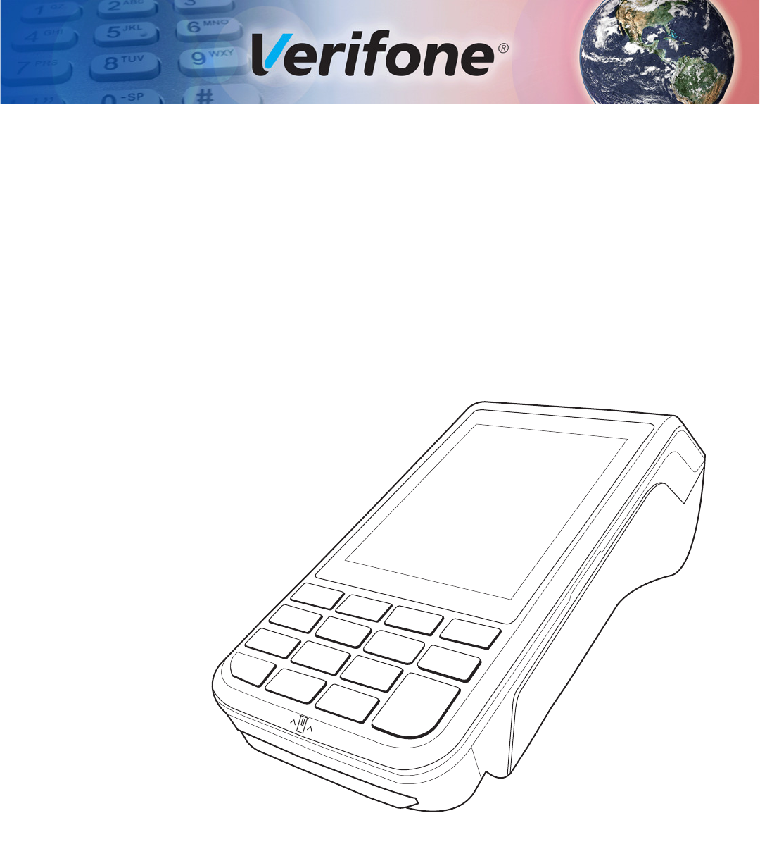
The terminal is a portable and battery-powered device designed to fit comfortably
during handheld consumer-facing applications. It features a colored 3.5” QVGA
display, touch screen, and backlit spill-resistant keypad. It supports a variety of
communication technologies including GPRS, 3G radio with GPS/A-GPS, 802.11
a/b/g/n wireless fidelity (Wi-Fi), and Bluetooth. Refer to Table 3 for a detailed list
of features available on VX 685 and VX 690.
Figure 1 VX 685/VX 690 Terminal

TERMINAL OVERVIEW
Features and Benefits
10 VX 685/VX 690 INSTALLATION GUIDE
Features and
Benefits
The terminal focuses on optimizing cost structure and providing better form factor.
It provides the right combination of features and functions in a sleek and
ergonomic device that fits in the palm of your hand.
Exceptional Ease of
Use
•Bold, ergonomic design—sleek, stylish, and lightweight for conveniently
handing the unit for PIN entry or other input.
•Large 3.5” QVGA display for boundless application possibilities and easy
readability under various lighting conditions.
•Touchscreen for icon-based applications or electronic signature capture
support.
•Intuitive telco-style keypad with large, colored control keys, and
interchangeably detects key presses from tactile keypad and the touchscreen.
•40 mm diameter paper roll with a trouble-free, drop-in, “clam shell” loading,
and dual tear bar that allows receipts to be torn in any direction.
•Quiet and fast integrated thermal printer with a rear placement to maximize
the user interface area.
•Unidirectional magnetic stripe card reader with an extended blade for optimal
card reading.
Performance and
Durability
•Fast transactions due to powerful 400 MHz ARM11 processor.
•High-capacity 3.7 V 2450 mAh Li-ion battery.
•Standard base for drop-and-go charging and full feature Bluetooth base for
VX 690 for full back-up connectivity options and support to some peripheral
device.
•Terminal and base support peripheral connection via the USB Host and USB
device ports. Bluetooth base also supports peripheral connection via the serial
connection port.
•Rounded corners and drop resistant to three feet on concrete floor to minimize
breakage.
•192 MB memory (128 MB flash, 64 MB RAM) with optional removable micro
SD flash memory.
Security
•Incorporates tamper-detection circuitry to resist unauthorized intrusion and
supports a broad spectrum of software-based security features.
•PCI 3.X approved for debit and other PIN-based transactions.
•EMV Level 1 Type Approval.
•Supports reliable security available including SSL, VeriShield file
authentication, and VeriShield Protect to help prevent fraud and other
intrusions.

TERMINAL OVERVIEW
Differences Between VX 685 and VX 690 Terminals
VX 685/VX 690 INSTALLATION GUIDE 11
Contactless
Capability
•Advanced contactless architecture that future-proofs investment with a single
contactless interface (SingleCl), SoftSAMs, and side-by-side application
architecture.
•On-screen tap zone (CTLS logo) for optimized user experience.
•Contactless version accepts EMV and mag-stripe contactless payments as
well as PIN-based transactions.
Communication
Technology
•GPRS/3G/GPS: Long-range wireless payment for retailers that have no
physical location limitations.
•Bluetooth®: Simple, plug-and-play installation for locations that need short-
range wireless capability.
•Wi-Fi: Ideal for retailers that need multiple wireless devices and have an
existing IP infrastructure.
Differences
Between VX 685
and VX 690
Terminals
VX 685 and VX 690 terminals are mostly identical and offer the same general
benefits. It is important to know the differences in their intrinsic features.
Table 3 Features Comparison
Features VX 685 GPRS VX 690 3G-BT VX 690 3G-BT-WiFi
Processor 400 MHz ARM 11 400 MHz ARM 11 400 MHz ARM 11
OS Verix OS Verix OS Verix OS
Memory 64 MB SDRAM/128
MB Flash
64 MB SDRAM/128
MB Flash
64 MB SDRAM/128 MB
Flash
Display 3.5” QVGA 3.5” QVGA 3.5” QVGA
Touchscreen Resistive type Capacitive Type Capacitive Type
Radio GPRS (Gemalto
BGS2-W)
3G (Cinterion
PHS8-P)
3G (Cinterion PHS8-P)
Bluetooth NA Yes Yes
Wi-Fi NA NA Yes
GPS NA Yes Yes
Magnetic card
reader
Triple Track, bi-
directional
Triple track, bi-
directional
Triple track, bi-
directional
Smart card
reader
ISO 7816, 1.8 V, 3
V, 5 V, synchronous
and asynchronous
cards
ISO 7816, 1.8 V, 3
V, 5 V, synchronous
and asynchronous
cards
ISO 7816, 1.8 V, 3 V, 5
V, synchronous and
asynchronous cards
SAM slots 222
SIM Single Dual Dual
Micro SD NA Yes Yes
Audio speaker NA Yes Yes
USB integrated 1 Host/client 1 Host/client 1 Host/client
Security PCI 3.0 PCI 3.0 PCI 3.0
CTLS NXP PN512 C2 NXP PN512 C2 NXP PN512 C2
Printer 30 lps 30 lps 30 lps

TERMINAL OVERVIEW
Differences Between VX 685 and VX 690 Terminals
12 VX 685/VX 690 INSTALLATION GUIDE
Battery 3.7 V DC/2450
mAh
3.7 V DC/2450
mAh
3.7 V DC/2450 mAh
Paper roll 40 mm 40 mm 40 mm
Charger 5 V DC/2.2 A 5 V DC/2.2 A 5 V DC/2.2 A
Dimension
(mm)
163 x 78 x 52 163 x 78 x 52 163 x 78 x 52
Table 3 Features Comparison (continued)
Features VX 685 GPRS VX 690 3G-BT VX 690 3G-BT-WiFi

VX 685/VX 690 INSTALLATION GUIDE 13
CHAPTER 2
Setup
This chapter describes the setup procedure for:
•Terminal Location.
•Inside the Shipping Carton.
•Terminal Features.
•Connection Port.
•Paper Roll.
•SIM Card.
•MSAM Card.
•Micro SD Card.
•Optional Devices.
•Battery Features.
•Terminal Power Source.
•Base Stations.
•3G, GPRS, and GPS Support.
•VX 690 BT/Wi-Fi Support.
•Smart Card Reader.
•Magnetic Card Reader.
•Contactless Smart Card Transaction.
Terminal
Location
The following are guidelines used to select an ideal location for the terminal.
Ease of Use
•Select a location convenient for both merchant and cardholder.
•Select a flat support surface, such as a countertop or table.
•Select a location near a power outlet, ECR, or computer connected to the
terminal. Do not string cables or cords across a walkway for safety.
Environmental
Factors
•Do not use the unit where there is high heat, dust, humidity, moisture, or
caustic chemicals or oils.
•Keep the unit away from direct sunlight and anything that radiates heat, such
as a stove or a motor.

SETUP
Inside the Shipping Carton
14 VX 685/VX 690 INSTALLATION GUIDE
•Do not use the terminal outdoors.
Electrical
Considerations
•Avoid using this product during electrical storms.
•Avoid locations near electrical appliances or other devices that cause
excessive voltage fluctuations or emit electrical noise (for example, air
conditioners, electric motors, neon signs, high-frequency or magnetic security
devices, or computer equipment).
•Do not use the terminal near water or in moist conditions.
Inside the
Shipping Carton
Open the shipping carton and carefully inspect its contents for possible tampering
or shipping damage. The terminal is a secure product. Tampering causes it to
cease to function or to operate in an unsecured manner.
Unpacking the
Shipping Carton
To unpack the shipping carton:
1Remove and inspect the contents of the shipping carton. The terminal ships in
multiple configurations, the carton may include all or any of the following:
•Terminal
•Power pack
•Paper roll
•Ethernet cable
•Telephone line cable
2Remove all plastic wrapping from the terminal and components.
3Remove the clear protective film from the display.
4Save the shipping carton and packing material for future repacking or moving
of the device.
CAUTION
The terminal is not waterproof or dustproof. It is intended for indoor use only. Any
damage to the unit from exposure to rain or dust can void any warranty.
WARNING
Do not use the terminal near water, including a bathtub, wash bowl, kitchen sink
or laundry tub, in a wet basement, or near a swimming pool to avoid shock or
damage.
WARNING
Do not use a tampered or damaged unit. The terminal comes equipped with
tamper-evident labels. If a label or component appears damaged, please notify
the shipping company and your Verifone service provider immediately.
SETUP
Terminal Features
VX 685/VX 690 INSTALLATION GUIDE 15
Terminal
Features
Familiarize yourself with the terminal features before continuing with the
installation process:
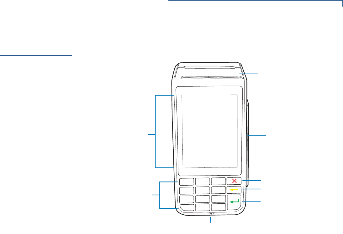
Figure 2 VX 685/VX 690 Features
Front Panel
The front panel offers the following features:
•A touchscreen display.
•A set of keys that include:
•A 12-key, telephone-style keypad (keypads may vary in style).
•Three color-coded function keys on the right side of the keypad (from top
to bottom: CANCEL, CLEAR, ENTER).
•A magnetic card reader, built into the right side. An icon shows the proper
swipe direction, with the stripe facing down and towards the keypad.
•A smart card reader, built into the unit’s front side. An icon indicates the proper
card position and insertion direction.
&$1&(/.(<
&/($5.(<
(17(5.(<
0$*1(7,&&$5'5($'(5
60$57&$5'5($'(5
7(/(3+21(67</(.(<3$'
49*$',63/$<728&+6&5((1
7+(50$/35,17(5
SETUP
Connection Port
16 VX 685/VX 690 INSTALLATION GUIDE
Connection Port
The terminal has one primary micro-USB port used for power and download.
Figure 3 Micro-USB Port on the Terminal
Paper Roll
A fast and quiet thermal printer is built into the terminal. You must install a roll of
thermal-sensitive paper in the printer before you can process transactions that
require a receipt or record.
The ITP uses a roll of single-ply and thermal-sensitive paper 40 mm in diameter. A
pink out-of-paper indicator line appears on the edge of the paper approximately
18 inches before the end of the roll. After this line appears, there is enough paper
remaining on the roll to conclude at least one transaction.
Installing or
Replacing a Paper
Roll
To install or replace a paper roll:
1Gently pull the latch on top of the terminal to unlock the compartment.
2Lift the printer cover up and back.
3Remove any partial roll of paper in the printer tray.
4Loosen the glued leading edge of the new roll of paper or remove the
protective strip, if applicable. Unwind the paper roll past any glue residue.
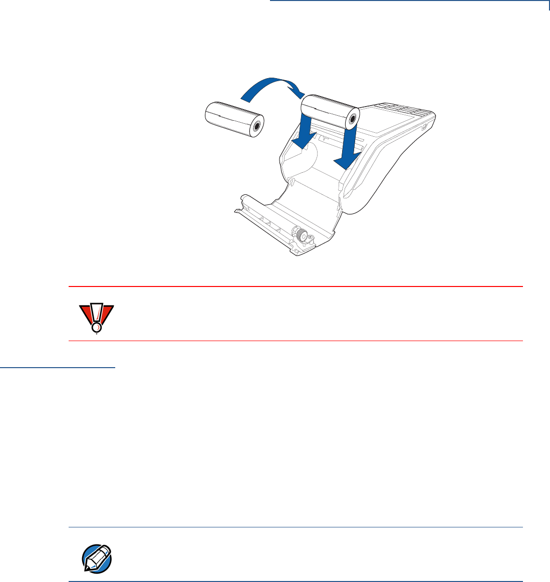
5Hold the roll so the paper feeds from the bottom of the roll when the terminal is
inverted.
CAUTION
Poor-quality paper can jam the printer and create excessive paper dust. Refer to
Accessories and Documentation to order high-quality Verifone paper. Store
thermal paper in a dry and dark area. Handle thermal paper carefully. Impact,
friction, temperature, humidity, and oils affect the color and storage
characteristics of the paper. Never load a roll of paper with folds, wrinkles, tears,
or holes at the edges in the print area.
SETUP
SIM Card
VX 685/VX 690 INSTALLATION GUIDE 17
6Drop the paper roll into the printer tray.
Figure 4 Installing Paper Roll Cover
SIM Card
VX 685 has a single SIM slot that enables communication to the network provider.
VX 690 supports dual SIM. SIM slot 1 is preferred for single SIM use. When dual
SIM is employed, it is ideal to use SIM cards from two different network providers.
This allows the terminal to switch SIMs when it detects poor signal or no network.
Installing or
Replacing a SIM Card
To install or replace a SIM card:
1Turn off the terminal.
2Place the terminal face down on a soft and clean surface to protect the lens
from scratches.
3Lift the battery pack to expose the SIM slots.
CAUTION
Gently press down on the paper roll cover to close it to prevent damaging the
print roller.
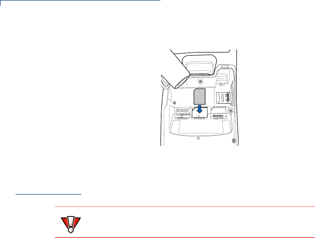
NOTE
Position the card’s gold contacts facing away from you, toward the unit. The card
slot in the terminal has a set of contacts. The SIM card has a notch on one corner
to ensure that it fits into the connector base in only one way.
SETUP
MSAM Card
18 VX 685/VX 690 INSTALLATION GUIDE
4Align the card to match the embossed number and carefully slide it into the
slots until fully inserted.
Figure 5 SIM Card Insertion
To replace SIM card, gently slide out the old SIM card before inserting a new
SIM.
MSAM Card
You may need to install one or two multiple security access module (MSAM) cards
or replace an old one.
Installing or
Replacing MSAM
Card
To install or replace MSAM cards:
1Power off the terminal.
2Place the terminal face down on a soft and clean surface to protect the lens
from scratches.
3Remove the back cover of the unit.
21
CAUTION
Observe standard precautions in handling electrostatically sensitive devices.
Electrostatic discharge can damage the equipment. Verifone recommends using
a grounded anti-static wrist strap.
SETUP
MSAM Card
VX 685/VX 690 INSTALLATION GUIDE 19
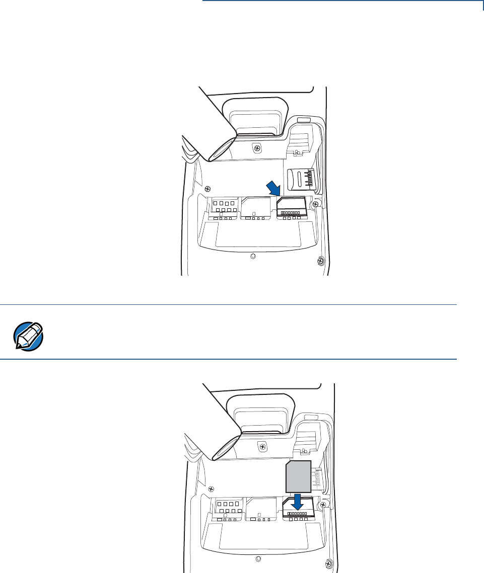
4Lift the battery pack to expose the SAM slots. The slots are located just below
the micro SD card slot.
Figure 6 SAM Slots
5Carefully slide the cards one at a time into the slots until fully inserted.
Figure 7 SAM Insertion
To replace SAM card, gently slide out the old SAM card before inserting a new
one.
21
NOTE
Position the card’s gold contacts facing away from you, toward the unit. The card
slot in the terminal has a set of contacts. The MSAM card has a notch on one
corner to ensure that it fits into the connector base in only one way.
21
SETUP
Micro SD Card
20 VX 685/VX 690 INSTALLATION GUIDE
Micro SD Card
VX 690 supports micro SD for additional memory.
Installing or
Replacing Micro SD
Card
To install or replace Micro SD card:
1Turn off the terminal.
2Place the terminal face down on a soft and clean surface to protect the lens
from scratches.
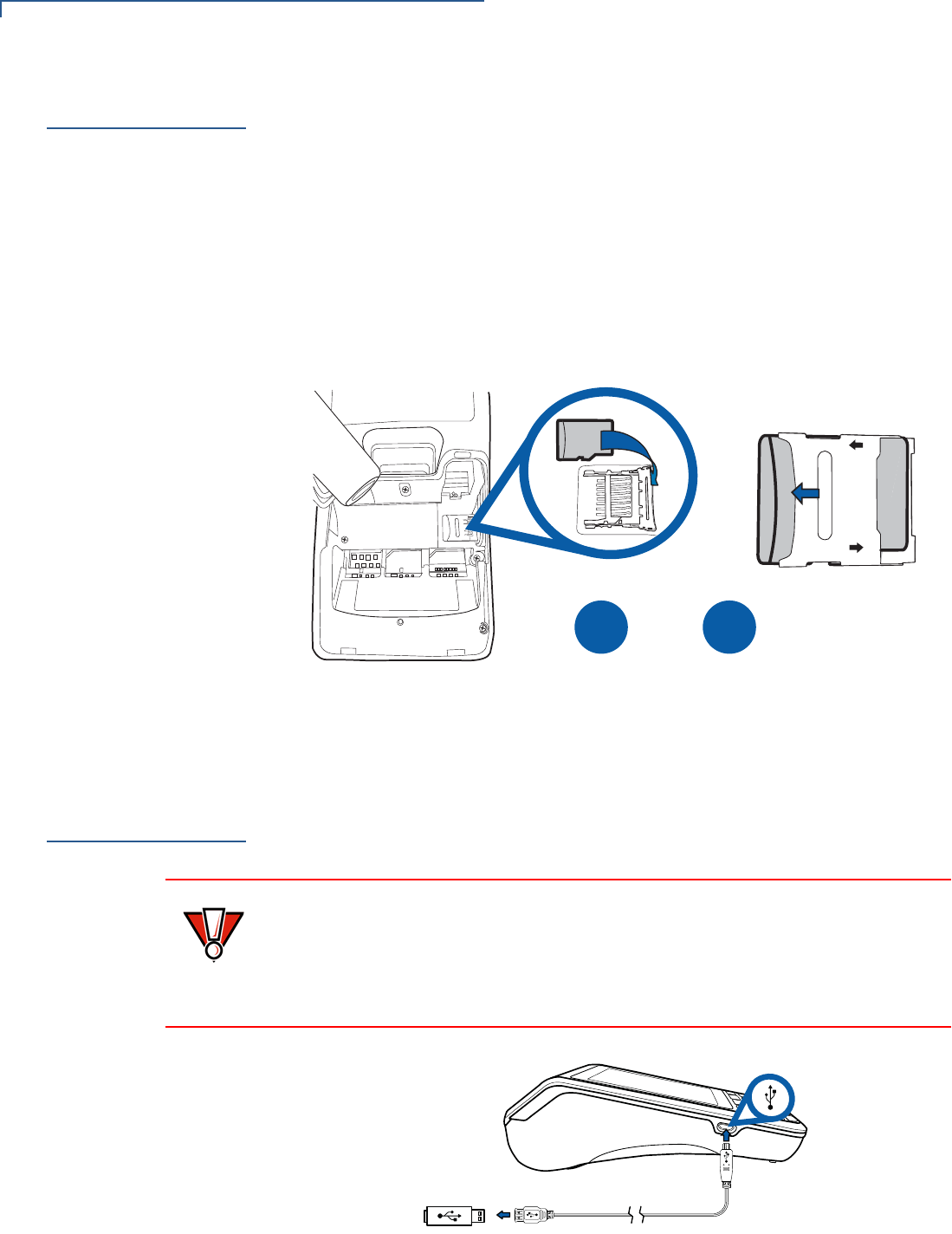
3Lift the battery pack to expose the micro SD card slot.
4Insert the micro SD card into its slot.
Figure 8 Inserting a Micro SD Card
To replace Micro SD card, gently slide out the old micro SD card before
inserting a new one.
Optional
Devices
The terminal supports peripheral devices designed for use with electronic point-of-
sale system such as biometric scanner and barcode reader via the Micro-USB
port.
Figure 9 Connecting Peripheral Devices to the Terminal via the Micro-
USB Port
LOCK
OPEN
B
A
21
CAUTION
Power limitations for peripheral devices should be considered. The side micro-
USB supports up to 300 mA. USB 1.1 supports up to 200 mA.
Reconnect the power cord only after you are finished connecting the peripheral
device(s). Refer to the user documentation supplied with those devices for
complete information about peripheral installation and use.

SETUP
Battery Features
VX 685/VX 690 INSTALLATION GUIDE 21
Battery Features
The terminal uses a single cell, 2450 mAh Li-ion battery (see Accessories and
Documentation for ordering information). The internal logic of the battery prevents
both overcharging and undercharging—a fault condition where the battery level
goes well below the minimum acceptable charge and the battery becomes
unusable.
The battery has a safety circuit that prevents cell damage from overcharge, over-
discharge, or overheating; and activates when the battery is left in an unused
terminal for extended periods.
•The battery is not customer-changeable and therefore should not be
disconnected and removed.
•Li-ion batteries are not affected by shallow charging. When the terminal has
no external power source or battery, the coin cell battery provides power to the
security circuit.
•Disconnecting and removing the battery, as well as unplugging the terminal
power pack, reduce the life of the coin cell battery, which does not recharge
and must be replaced when drained.
•Conserve battery power by turning the terminal off when not in use.
•Keep the Li-ion battery inserted in the terminal and power up the terminal
periodically to check the battery charge. Do not let the battery charge fall
below 10% for extended periods of time as this may permanently diminish the
battery capacity. Recharge the battery by attaching the micro-USB end of the
power pack to the terminal and plugging the other end of the power pack into a
wall outlet.
See Battery Information for more specific information about battery.
Battery Life
VX 685 terminal keeps track of the charging current going into the battery. The
battery is considered healthy until its capacity is reduced to 70% of the theoretical
capacity. Check the batteries when the number of cycles exceeds 600 full cycles.
get_battery_value()supports battery life:
•int get_battery_value(BATTERYLIFE);
•int get_battery_value(BATTERYCYCLES);
See Verix eVo Volume I: Operating System Programmers Manual, VPN -
DOC00301 for more information.
Battery Behavior
The terminal shifts to power pack mode and starts up automatically when the
terminal is connected to a non-battery power source, regardless of the battery
charge state.
SETUP
Terminal Power Source
22 VX 685/VX 690 INSTALLATION GUIDE
Manual Startup
Hold the green key down for about four seconds until the terminal displays the
startup screen. The time required to hold the green key down to power up the
terminal is configurable (see VX 690 Reference Guide, VPN - DOC260-004-EN for
more information). The terminal lights up once power is on.
Manual Shutdown
Hold the red key down for about four seconds until the terminal displays the
shutdown verification screen. The time required to hold the red key down to shut
down the terminal is configurable (see VX 690 Reference Guide, VPN - DOC260-
004-EN for more information).
Terminal Power
Source
The terminal is either powered by an external power pack or the single cell Li-ion
rechargeable battery, which can be charged in the terminal by the AC/DC power
pack through the micro-USB connector for VX 690 and pin connector for VX 685.
When you have finished installing the necessary cards and/or optional devices,
you are ready to connect the terminal to the power source.
NOTE
When the terminal has power and an application is loaded, the application starts
after the initial Verifone copyright screen. If no application is loaded,
DOWNLOAD NEEDED appears on the display after the initial Verifone copyright
screen.
WARNING
Do not connect the terminal to the power supply until all peripherals are attached.
Using an incorrectly rated power supply can damage the unit or cause it not to
work properly. Use only a power pack with P/N PWR260-001-XX-A for VX 690
and P/N PWR262-001-XX-A for VX 685. See Specifications for detailed power
supply specifications.
Do not plug the power pack into an outdoor outlet or operate the terminal
outdoors. Disconnecting power during a transaction can also cause unstored
data files to be lost.
NOTE
Verifone recommends installing a power surge protector to protect against
possible damage caused by lightning strikes and electrical surges.
SETUP
Terminal Power Source
VX 685/VX 690 INSTALLATION GUIDE 23
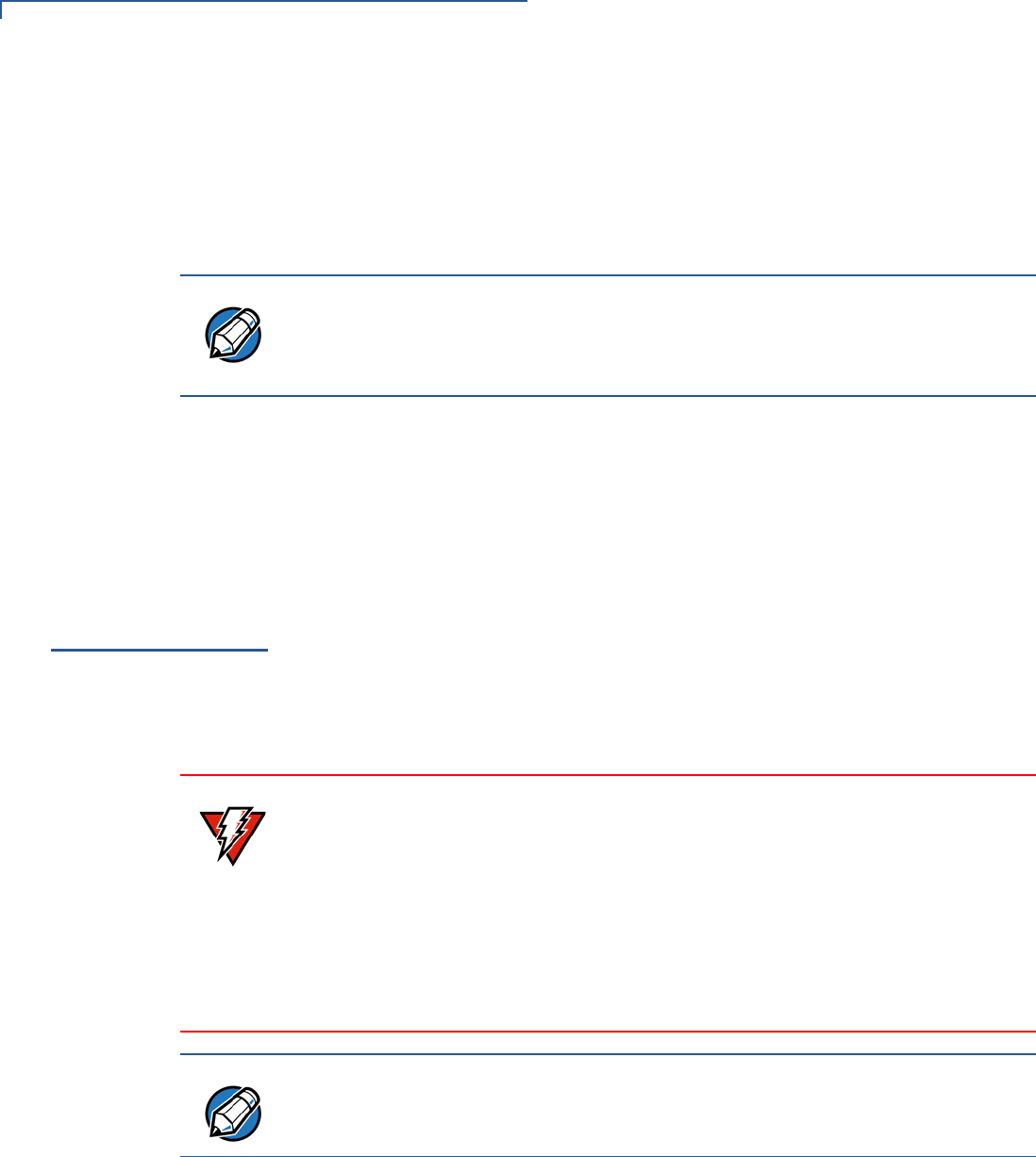
Connecting VX 690
Terminal to a Power
Source
To connect VX 690 terminal to a power source:
1Insert the micro-USB connector to the micro-USB port found on the side of the
terminal.
2Plug the AC power cord into a wall outlet or power surge protector.
Figure 10 Connecting VX 690 to Power Source
Connecting VX 685
Terminal to a Power
Source
To connect VX 685 terminal to a power source:
1Insert the pin connector into the pin slot located at the back of the terminal.
2Plug the AC power cord into a wall outlet or power surge protector.
Figure 11 Connecting VX 685 to Power Source
SETUP
Base Stations
24 VX 685/VX 690 INSTALLATION GUIDE
Base Stations
Verifone ships variants of the base station for different markets. Your base may
have a different configuration.
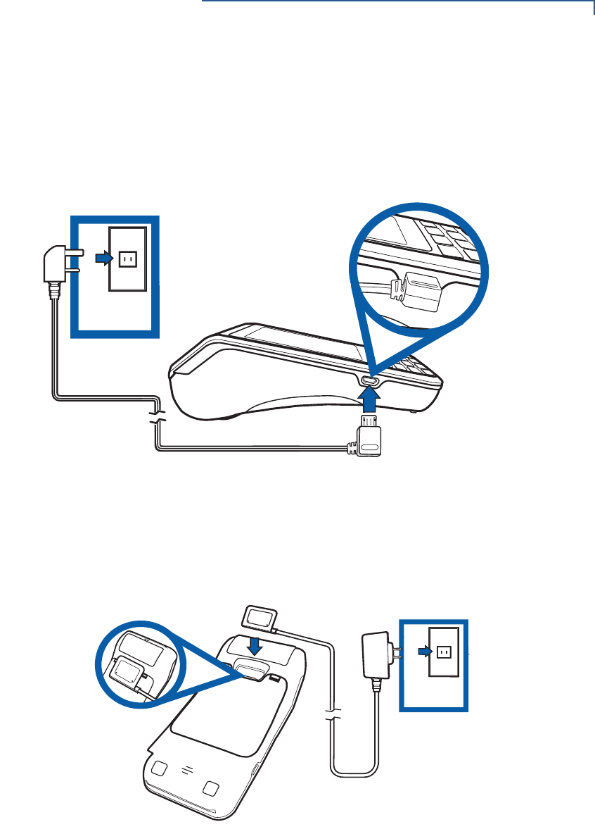
Charging Base
A base to charge the terminal and provide a docking station when the terminal is
not in use. The base can be positioned on a countertop.
Figure 12 Charging Base
BT Base
A base that supports power, dial-up, Ethernet, powered RS-232, USB device
connectivity, USB Host, and Bluetooth device. Apart from charging the battery, it
allows the terminal to use dial and Ethernet options, support peripheral devices,
download/debug tasks, and conduct transactions over Bluetooth.
Figure 13 BT Base
SETUP
Base Stations
VX 685/VX 690 INSTALLATION GUIDE 25
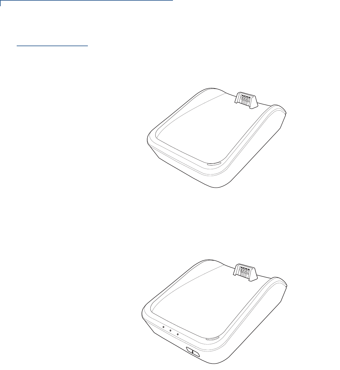
Powering Up the Base To power up the base:
1Insert the micro-USB plug into the micro-USB port on the base.
2Plug the AC power cord into a wall outlet or a power surge protector.
Figure 14 Connecting Base to Power Source
Terminal and Base
The terminal can be placed on the base when not in use. This ensures continuous
charging of the battery.
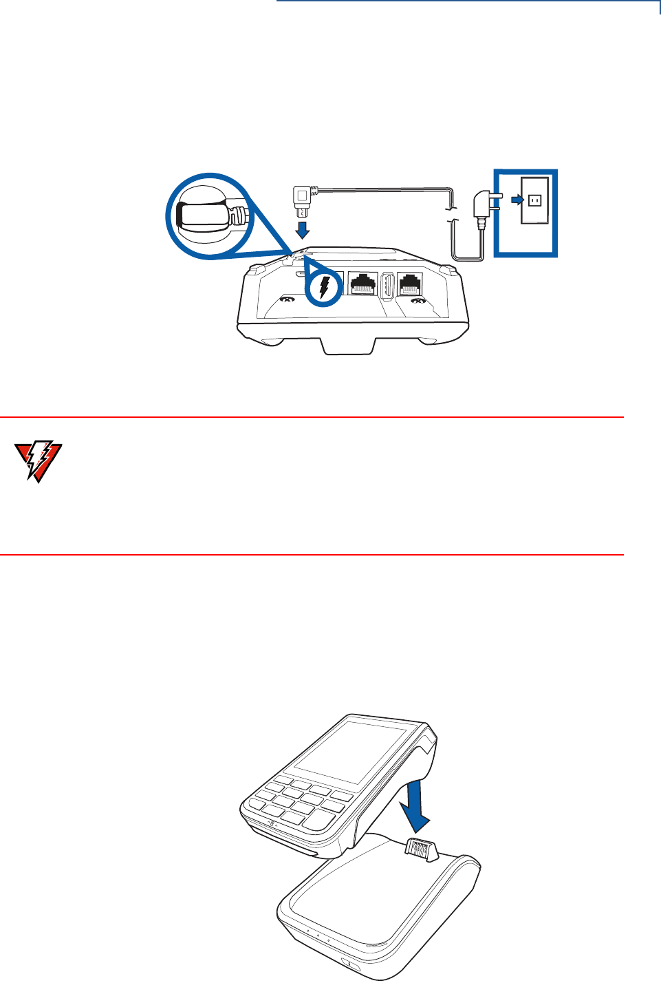
Docking the Terminal
on the Base
To dock the terminal on the base:
1Place the top portion of the terminal on the base. Ensure that the recess on
the bottom of the terminal sits on top of the docking connector.
Figure 15 Docking the Terminal on the Base
COM
ETH
WARNING
Using an incorrectly rated power supply can damage the unit or cause it not to
work properly. Use only a power pack with P/N PWR260-001-XX-A. See
Specifications for detailed power supply specifications.
Do not plug the power pack into an outdoor outlet or operate the terminal
outdoors. Disconnecting power during a transaction can also cause unstored
transaction data files to be lost.
SETUP
Base Stations
26 VX 685/VX 690 INSTALLATION GUIDE
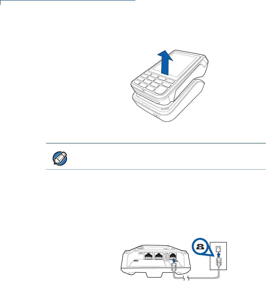
Undocking the
terminal from the
base
To undock the terminal from the base:
1Gently lift the terminal from the base.
Figure 16 Undocking the Terminal from the Base
Dial-up and Ethernet
Connections
The terminal allows for dial-up and Ethernet connections for full back-up
connectivity.
Creating a Dial-Up
Connection
To create a dial-up connection:
1Connect the telephone cable to the communication port on the base.
2Route the other end of the cable directly to a telephone wall jack. This is a
direct connection and the line is dedicated to the terminal.
Figure 17 Direct Telephone Connection
NOTE
When conducting customer transactions, you can remove the terminal from the
base.
COM
ETH
SETUP
Base Stations
VX 685/VX 690 INSTALLATION GUIDE 27
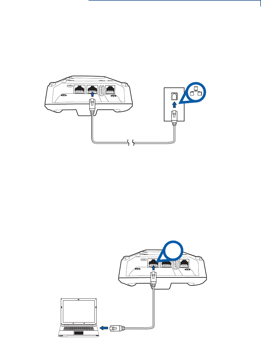
Creating an Ethernet
Connection
To create an Ethernet connection:
1Connect the Ethernet cable to the port on the base.
2Route the other end of the cable directly to a data wall jack (or router/hub).
Figure 18 Ethernet Connection
Powered Serial
The powered serial on the base can be used in debug options or downloading
applications.
Connecting to the
Powered Serial
To connect to the powered serial:
1Connect the RS-232 cable to the COM port on the base.
2Route the other end of the cable to the PC.
Figure 19 Connection to the COM Port
COM
ETH
COM
ETH
RS-232
SETUP
3G, GPRS, and GPS Support
28 VX 685/VX 690 INSTALLATION GUIDE
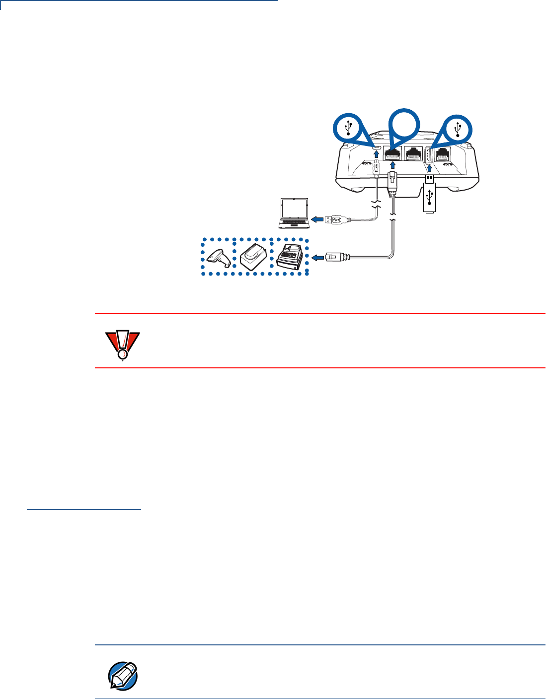
External Devices
The base supports peripheral devices such as electronic cash register, check
reader, barcode reader, and biometric scanner through a serial connection. Micro-
USB port is for PC connection and USB Host port is for USB flash drive.
Figure 20 Connecting Peripheral Devices
Connecting
Peripherals or
External Devices
To connect peripherals or external devices:
1Connect the micro-USB/USB cable of the device to the micro-USB/USB port
of the base.
2Refer to the user documentation supplied with those devices for complete
information about the peripheral installation and use.
3G, GPRS, and
GPS Support
VX 690 uses the Cinterion PHS8-P radio module. This module provides wireless
connectivity using HSPA+ technology. The PHS8-P radio module is optimized for
high bandwidth and allows a downlink speed of 14.4 Mbps and an uplink speed of
5.7 Mbps.
GPS Receiver
The Cinterion PHS8-P radio module on VX 690 integrates a GPS receiver that
offers the full performance of GPS/A-GPS technology, allowing customers to
implement geo-fencing applications.
3G/GPRS
Allows for a wider range of communication for wireless transaction payment using
the available operator-provided 3G infrastructure.
COM
ETH
B
B
RS-232
CAUTION
Remove the power cord from the terminal before connecting any peripheral
device. Reconnect the power cord only after you have finished connecting the
peripheral device(s).
NOTE
VX 685 uses integrated Gemalto BGS2-W module to support GSM/GPRS radio
features.
SETUP
VX 690 BT/Wi-Fi Support
VX 685/VX 690 INSTALLATION GUIDE 29
VX 690 BT/Wi-Fi
Support
VX 690 Wi-Fi/BT integrated module uses Broadcomm BCM4330 chip, which
provides SDIO interface for Wi-Fi and UART interface for Bluetooth. The module
includes an integrated WLAN RF transceiver for Wireless LAN systems with
advanced power management unit, and an integrated radio transceiver for
Bluetooth wireless systems.
Bluetooth Support
VX 690 uses the Bluetooth base station. Up to seven devices can be registered
with the same communications device, but only one transaction may be
undertaken at a time. Do not pair more than three terminals with the base station.
When more than three terminals are required, additional base stations must be
suitably positioned on site to obtain maximum radio coverage.
The terminal and the Bluetooth base station are both Class 1 Bluetooth devices
providing secure radio communication up to 100 meters, unobstructed. The
terminal may be registered (paired) with more than one base station. It must be
paired to secure the communication. The terminal may easily be switched among
paired devices using the standard menu options provided in Verix Commserver.
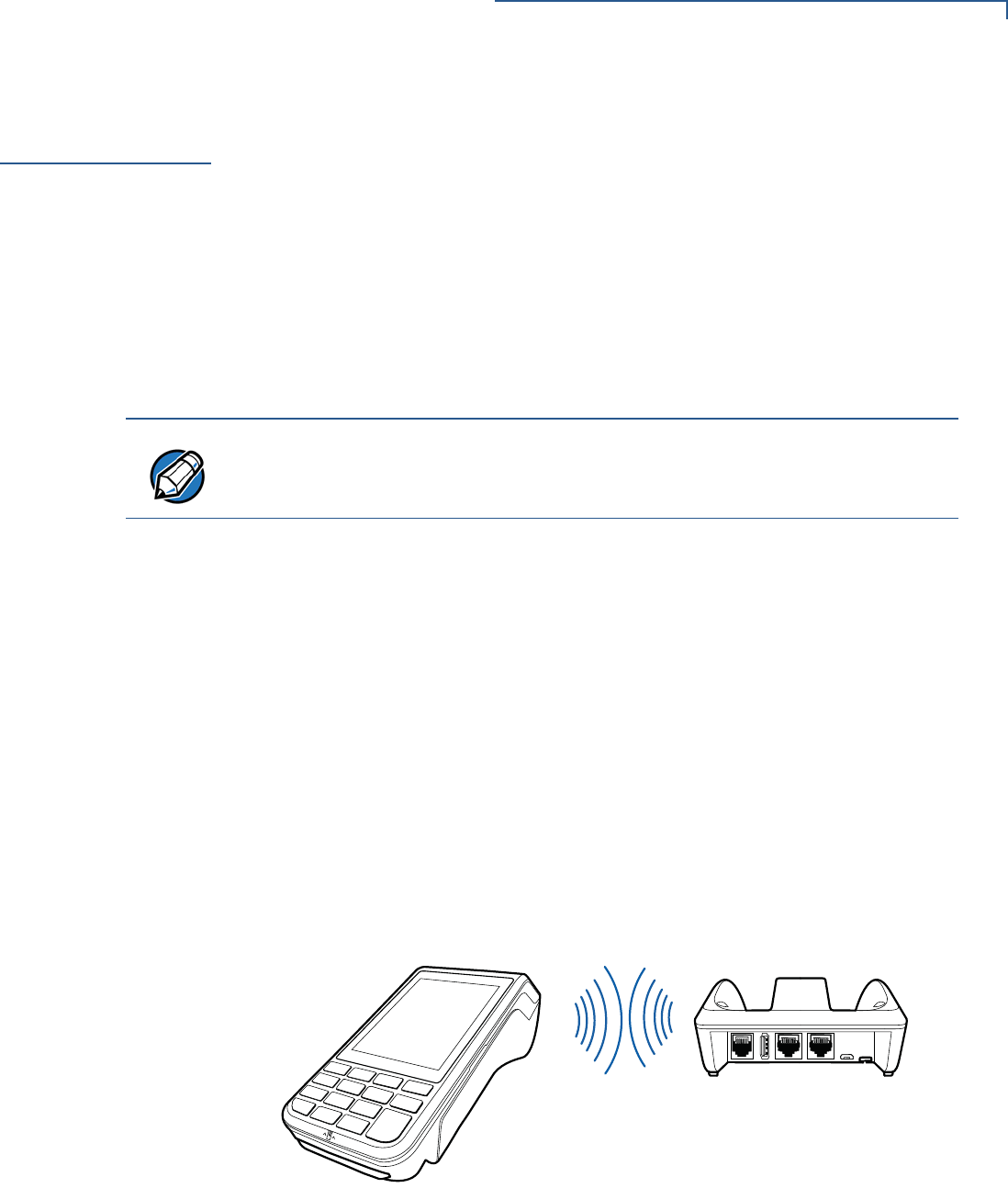
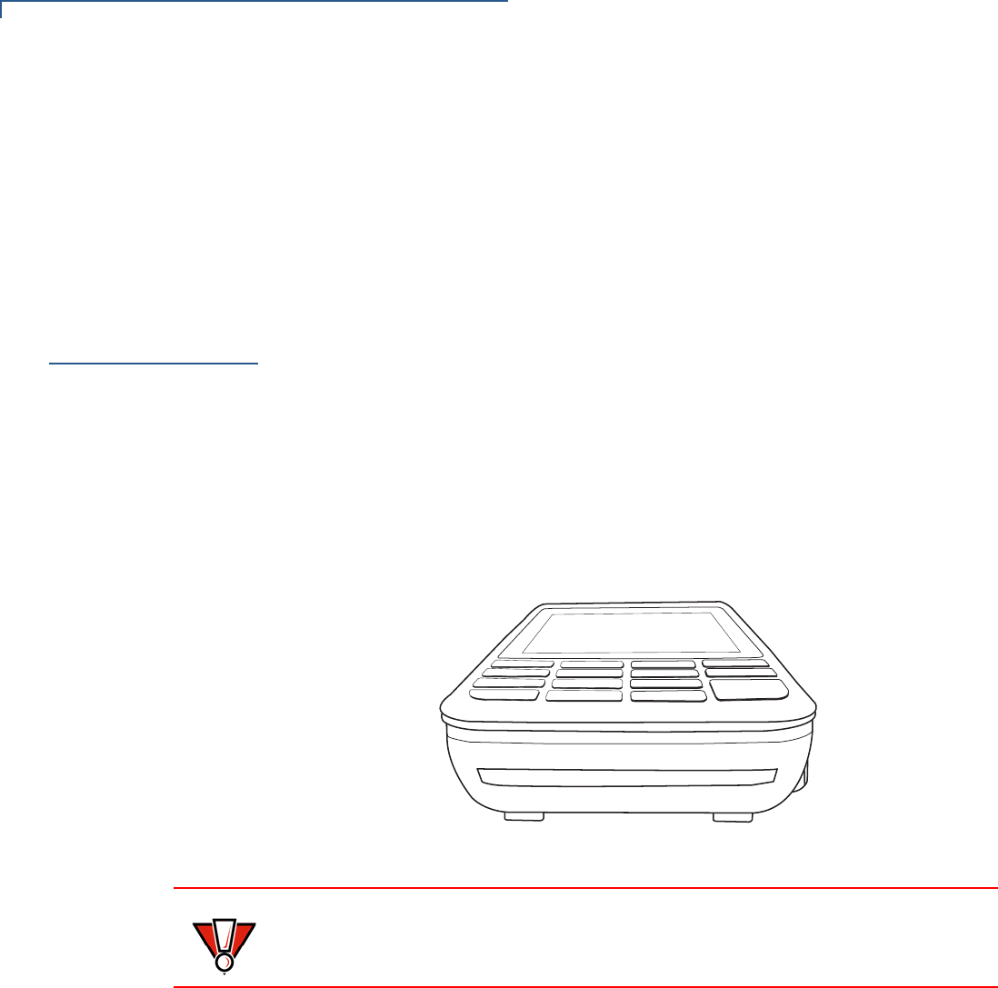
Establishing
Bluetooth
Connections
To establish Bluetooth connections:
1Ensure the terminal is not more than five meters away from the Bluetooth
Base Station for initial pairing.
2Terminal and Bluetooth Base Station must be powered on.
3Follow the on-screen instructions displayed on the terminal.
Bluetooth base relays wireless data received from the terminal via modem and
then transmits back the response to the terminal.
Figure 21 Terminal Communicating with a Bluetooth Base
Bluetooth Base Station should be placed in a position that services all of the card
payment areas in your premises to improve the range performance of the
terminal. The ideal placement is to position the base station within line of sight of
all areas of card acceptance.
NOTE
The terminal can only communicate to a base station to which it is paired.
SETUP
VX 690 BT/Wi-Fi Support
30 VX 685/VX 690 INSTALLATION GUIDE
Searching for a
Bluetooth Base
Station
Use the terminal to search and establish a connection between the Bluetooth
version of the terminal and the Bluetooth Base Station.
To search for a Bluetooth Base Station using the terminal:
1Power on the terminal.
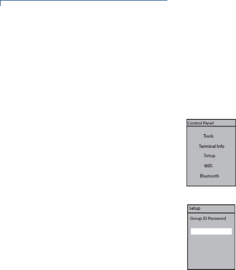
2Select the Options menu shown on the terminal display.
3Select Bluetooth on the Network Control Panel.
4Click Bluetooth to access the Bluetooth menu.
5Enter your password and press the Enter key to access the Setup menu.
SETUP
VX 690 BT/Wi-Fi Support
VX 685/VX 690 INSTALLATION GUIDE 31
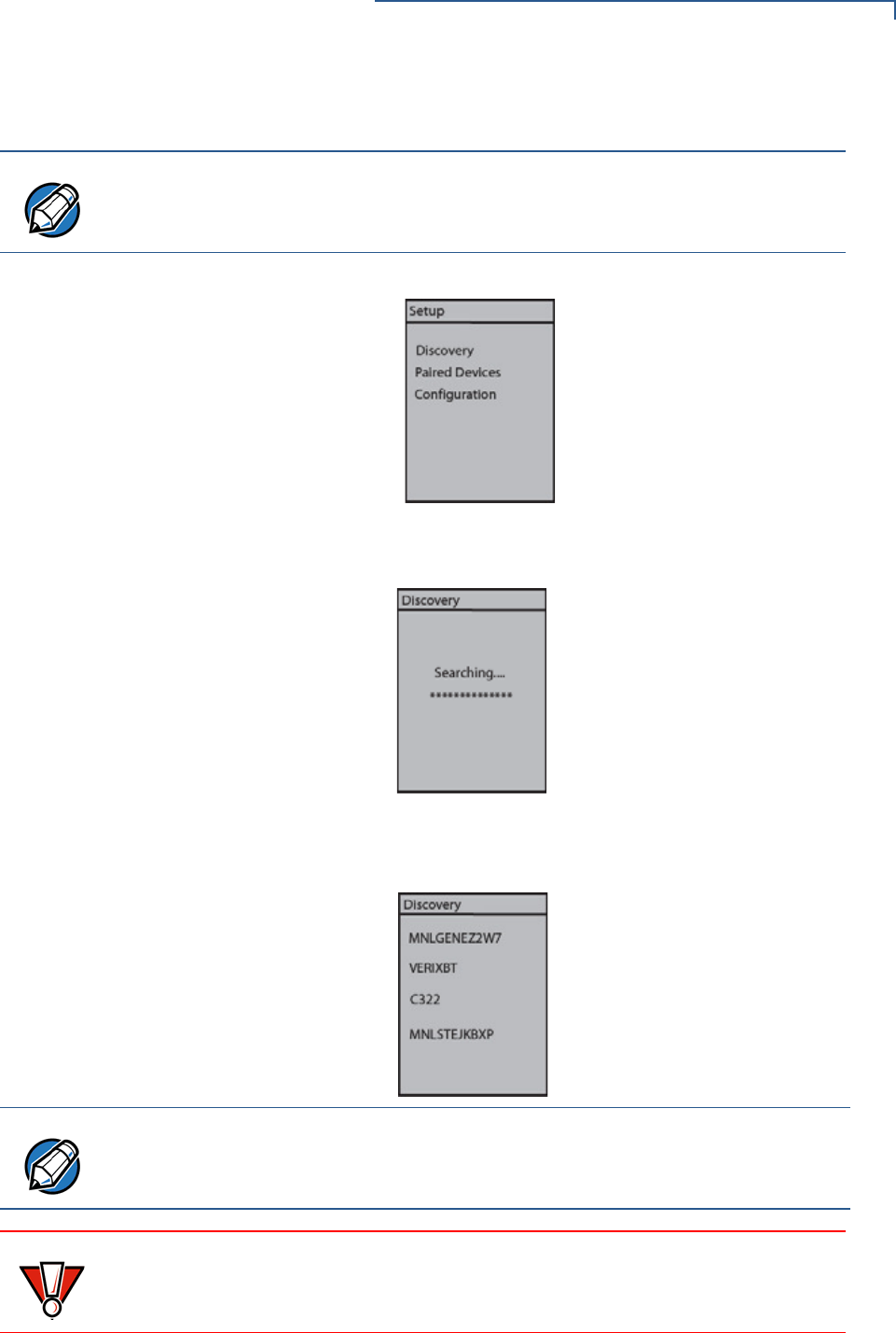
6Press Enter key to start searching for a base station.
There is a short delay as the terminal searches for the base station. The
message is shown on the terminal display.
The base station’s name is displayed once the terminal discovers the
Bluetooth Charging Base Station.
NOTE
Discovery is selected by default on the Setup menu.
NOTE
Press the Bluetooth switch found in front of the Bluetooth Base if the devices are
unable to find each other after two minutes. The three LEDs will blink after
pressing the switch indicating that the Bluetooth Base is discoverable.
CAUTION
Pressing the Bluetooth switch while there is an existing Bluetooth connection
may result in loss of connection, loss of modem profile, and loss of all modem
settings/configuration.
SETUP
VX 690 BT/Wi-Fi Support
32 VX 685/VX 690 INSTALLATION GUIDE
Pairing the Terminal
with a Bluetooth Base
Station
Even after you have successfully searched for a Bluetooth Base Station using the
terminal, you will not be able to conduct Bluetooth transactions until you have
paired the terminal and the base station.
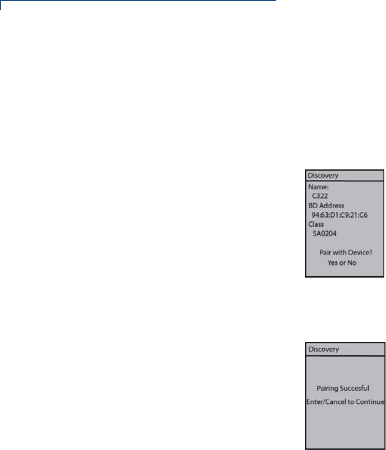
To pair the terminal with the base station:
1Navigate to the BT Devices menu.
2Select the base station’s name and press the Enter key.
The BT Devices menu appears on the terminal screen if pairing is successful.
The name of the Bluetooth Base Station appears on the first line of the BT
Devices menu.
If everything is connected properly and the terminal is unable to go online, refer to
Troubleshooting Guidelines.
Setting the
Connection
Information for a
Paired Device
To set the connection information for a paired device:
1Select Paired Device.
2Select a device from the list.
3Select either Ethernet, Modem, or Serial (this is for XPS019) on the BT Device
Port.

SETUP
VX 690 BT/Wi-Fi Support
VX 685/VX 690 INSTALLATION GUIDE 33
Pairing with Another
Bluetooth Charging
Base Station
The terminal may be paired with additional Bluetooth Base Station once the
terminal is paired with a Bluetooth Base Station and initialized.
To pair a terminal with another Bluetooth Base Station:
1Select Discovery on the terminal’s Setup menu and press Enter.
2Select the appropriate base station name displayed on the terminal and press
Enter.
3Select Yes on the Discover menu when Pair with Device screen appears.
The terminal and base station are then paired. The terminal makes the new
Bluetooth Base Station the default pairing device.
If everything is connected properly and the terminal is unable to go online, refer to
Troubleshooting Guidelines.
Removing a Paired
Bluetooth Charging
Base Station
To remove a Bluetooth Base Station to which a terminal has been paired:
1Navigate to the BT Devices menu.
2Select the Bluetooth Base Station you want to remove as a pair.
3Select Remove and press the Enter key.
The Bluetooth Base Station’s name will disappear from the display when the
base station is removed.
Removing a Paired
Device via Network
Control Panel of EOS
To remove a paired device via Network Control Panel of EOS:
1Select Bluetooth on the Menu.
2Select Setup on the Bluetooth menu.
3Select a paired device on the Setup menu.
4Select Remove.
NOTE
Make sure the terminal is within five meters from the Bluetooth Base Station,
which must be powered on.
SETUP
Smart Card Reader
34 VX 685/VX 690 INSTALLATION GUIDE
Wireless
Transaction
VX 690 supports wireless transactions.
Conducting Wireless
Transaction
To conduct a wireless transaction:
1Ensure the terminal is in an optimal position for transmitting.
2Follow the on-screen instructions provided with your application.
Smart Card
Reader
The smart card transaction procedure can vary depending on the application.
Verify the proper procedure with your application provider before performing a
smart card transaction.
Using the Smart Card
Reader
To use the smart card reader:
1Position the smart card with the gold contacts facing upward.
2Insert the card into the smart card reader slot in a smooth, continuous motion
until it sets firmly.
3Remove the card only when the display indicates the transaction is complete.
Figure 22 Smart Card Reader
CAUTION
Leave the smart card in the card reader until the transaction is completed.
Premature card removal can invalidate a transaction.
SETUP
Magnetic Card Reader
VX 685/VX 690 INSTALLATION GUIDE 35
Magnetic Card
Reader
The terminal has a magnetic card reader that uses a triple track stripe reader. This
gives the unit greater reliability over a wide range of swipe speeds and operating
environments.
Using the Smart Card
Reader (Credit/Debit
Card Transaction)
To use the smart card reader (credit/debit card transaction):
1Position a magnetic card with the stripe in the card reader and facing the
keypad.
2Swipe it through the magnetic card reader starting from the top of the unit
downward.
Figure 23 Using the Magnetic Card Reader
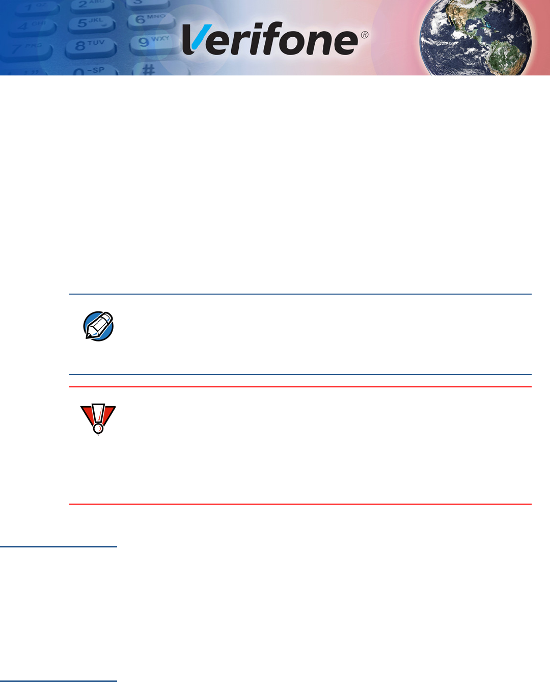
Contactless
Smart Card
Transaction
The terminal supports contactless transactions through an integrated contactless
module. The terminal only becomes active for contactless smart card transactions
when initialized by an application.
Performing a
Contactless Smart
Card Transaction
To perform a contactless smart card transaction:
1Gently tap the card onto or hold the card (within 4 cm) against the surface of
the RFID canopy.
2An activated LED visual on the display accompanied by a short beeping sound
indicates a successful transaction.
Figure 24 Contactless Smart Card Transaction
CAUTION
Do not let metallic surfaces come in contact with the contactless module to
ensure that it works properly.

SETUP
Contactless Smart Card Transaction
36 VX 685/VX 690 INSTALLATION GUIDE

VX 685/VX 690 INSTALLATION GUIDE 37
CHAPTER 3
Specifications
This chapter discusses power requirements, dimensions, and other specifications
of the terminal.
Power Rating
•5 V DC, 2.2 A
Power Pack
•PWR260-001-XX-A (VX 690)
•PWR262-001-XX-A (VX 685)
•UL/cUL, ITE listed, LPS power supply
•Input rated: 100-240 V AC, 50/60 Hz
•Output rated: 5 V DC, 2.2 A, 11 W
Temperature
•Operating temperature: 0° to 50° C (32° to 122° F)
•Storage temperature: -20° to 70° C (-4° to 158° F)
External
Dimensions
•Length: 173.25 mm (6.82 in.)
•Width: 87 mm (3.43 in.)
•Depth: 31.7 mm (1.25 in.)
Weight
•Unit weight: 0.27 kg (0.6 lbs)
•Shipping weight: 0.850 kg (1.9 lbs)
Processor
•400 MHz ARM 11
Memory
•192 MB memory (128 MB flash, 64 MB RAM)
Display
•3.5” QVGA
•Supports up to 26 lines x 26 characters
Magnetic Card
Reader
•Triple track (tracks 1, 2, 3), high coercivity, bi-directional
Primary Smart
Card
•ISO 7816, 1.8 V, 3 V, 5 V
•Synchronous and asynchronous cards

SPECIFICATIONS
SAM Card Reader
38 VX 685/VX 690 INSTALLATION GUIDE
SAM Card
Reader
The terminal has two Security Access Modules (SAMs).
Keypad
•3 x 5 Secure Keypad Matrix
•Keys can be simulated on touchscreen
Peripheral Ports
The micro-USB port on the terminal and on the base supports peripheral
attachment such as USB flash, biometric scanner, and barcode reader. Micro-
USB to USB converter adaptor is used for USB flash drive, application download,
and debugging.
Security
Complies to PCI 3.x plus country specifics.

VX 685/VX 690 INSTALLATION GUIDE 39
CHAPTER 4
Maintenance and Cleaning
Your terminal device is a product of superior design and craftsmanship and should
be treated with care. It has no user-serviceable parts. The following suggestions
will help you protect your warranty coverage.
•Keep the device dry. Precipitation, humidity, and all types of liquids or moisture
can contain minerals that will corrode electronic circuits. If your device does
get wet, switch off the power, and allow the device to dry completely before
replacing it.
•Do not use or store the device in dusty and dirty areas. Its moving parts and
electronic components can be damaged.
•Do not store the device in hot areas. High temperatures can shorten the life of
electronic devices, damage batteries, and warp or melt certain plastics.
•Do not store the device in cold areas. Moisture can form inside the device and
damage electronic circuit boards when the device returns to its normal
temperature.
•Do not drop, knock, or shake the device. Rough handling can break internal
circuit boards and fine mechanics.
•Do not use harsh chemicals, cleaning solvents, or strong detergents to clean
the device. Use only a soft, clean, and dry cloth for cleaning.
•Do not paint the device. Paint can clog the moving parts and prevent proper
operation.
•Keep the device free from any small and loose items (such as paper clips,
staples, or coins) that could accidentally get inside it through an opening, such
as the SD card reader slot or the primary smart card reader slot.
•Do not attempt to open the device other than as instructed in this guide. This
device has security features that protect it from tampering. For example, the
file content will be deleted if the device’s outer casing is opened.
These suggestions apply equally to your terminal device, or any of its attachments
or accessories. If your device is not working properly, take it to the nearest
authorized service facility for servicing or replacement. For your safety, have this
device serviced only by a Verifone-authorized service provider.
CAUTION
Never use thinner, trichloroethylene, or ketone-based solvents – they can
deteriorate plastic or rubber parts. Do not spray cleaners or other solutions
directly onto the keypad or display.

MAINTENANCE AND CLEANING
Additional Safety Information
40 VX 685/VX 690 INSTALLATION GUIDE
Additional
Safety
Information
The following are additional safety information in using this device.
Power Adapter
Use only the power adapter that came with your device. Adapters for other
electronic devices may look similar, but they may affect your device’s performance
or damage it.
Potentially
Explosive
Environments
Do not use this device in any area with a potentially explosive atmosphere. Follow
all signs and instructions. Potentially explosive atmospheres include areas where
you would normally be advised to turn off your vehicle engine. Sparks in such
areas could cause an explosion or fire resulting in bodily injury or even death.
Card Readers
Do not attempt to clean the card readers. Doing so can void any warranty. Contact
your Verifone distributor or service provider for card reader service.

VX 685/VX 690 INSTALLATION GUIDE 41
CHAPTER 5
Service and Support
Contact your local Verifone representative or service provider for any problems on
your terminal.
For product service and repair information:
•USA – Verifone Service and Support Group, 1-800-834-4366,
Monday - Friday, 8 A.M. - 8 P.M., Eastern time.
•International – Contact your Verifone representative.
Service Returns
You must obtain a Merchandise Return Authorization (MRA) number before
returning the terminal to Verifone. The following procedure describes how to
return one or more terminals for repair or replacement (U.S. customers only).
Returning One or
More Terminals for
Repair or
Replacement
1Gather the following information from the printed labels on the bottom of each
terminal to be returned:
•Product ID, including the model and part number. For example, “VX 690”,
“m260-xxx-xx”, and “PTID xxxxxxxx.”
•Serial number (S/N xxx-xxx-xxx).
2Obtain the MRA numbers by completing the following:
•Call Verifone within the United States toll-free at 1-800-Verifone and follow
the automated menu options.
•Select the MRA option from the automated message. The MRA
department is open Monday–Friday, 8 A.M.–8 P.M., Eastern time.
•Give the MRA representative the information gathered in Step 1.
If the list of serial numbers is long, you can fax the list, along with the
information gathered in Step 1, to the MRA department at 1-727-953-
4172 (U.S.).
•Address the fax clearly to the attention of the “Verifone MRA Dept.”
Include a telephone number where you can be reached and your fax
number.
•Complete the Inquiry Contact Form at http://www.verifone.com/aboutus/
contact/contact_form.cfm.
NOTE
For international customers, please contact your local Verifone representative for
assistance with your service, return, or replacement.

SERVICE AND SUPPORT
Accessories and Documentation
42 VX 685/VX 690 INSTALLATION GUIDE
•Address the Subject box with to “Verifone MRA Dept.”
•Reference the model and part number in the Note box
3Describe the problem(s).
4Provide the shipping address where the repaired or replacement unit must be
returned.
5Keep a record of the following items:
•Assigned MRA number(s).
•Verifone serial number assigned to the terminal you are returning for
service or repair (serial numbers are located on the bottom of the unit).
•Shipping documentation, such as air bill numbers used to trace the
shipment.
•Model(s) returned (model numbers are located on the Verifone label on
the bottom of the terminal).
Accessories and
Documentation
Verifone produces accessories and documentation for the terminal. Refer to the
part number in the left column when ordering.
Verifone Online Store at www.store.verifone.com
•USA – Verifone Customer Development Center, 1-800-834-4366,
Monday - Friday, 7 A.M. - 8 P.M., Eastern time
•International – Contact your Verifone representative
Below are accessories used with your terminal. Contact your Verifone distributor
to determine which of the accessories fit your requirements.
NOTE
One MRA number must be issued for each terminal you return to Verifone, even
if you are returning several of the same model.
Table 4 Accessories and VPNs
Accessory Part Number Description
Power pack PWR260-001-XX-A VX 690 DC power pack
PWR262-001-XX-A VX 685 DC power pack
Printer paper PPR260-001-01-A 40 mm
Verifone cleaning Kit VPN 02746-01 Cleaning kit
Serial dongle VPN M267-D08-00
Telephone line cable VPN CBL000-001-01-A 2.1-meter (7-foot) telephone
line cable, black, with
modular RJ11-type
connectors)

SERVICE AND SUPPORT
Accessories and Documentation
VX 685/VX 690 INSTALLATION GUIDE 43
Refer to the following set of documents to learn more about the terminal:
VX 690 Certifications and Regulations Sheet VPN - DOC260-001-EN
VX 690 Quick Installation Guide VPN - DOC260-002-EN
VX 685/VX 690 Reference Guide VPN - DOC260-004-EN
VX 690 Charging Base Certifications and
Regulations Sheet
VPN - DOC260-005-EN
VX 690 BT Base Certifications and Regulations
Sheet
VPN - DOC260-006-EN
VX 685/VX 690 Charging Base Quick Installation
Guide
VPN - DOC260-007-EN
VX 690 BT Base Quick Installation Guide VPN - DOC260-008-EN
VX 690 3G-BT-WiFi Certifications and Regulations
Sheet
VPN - DOC260-009-EN
VX 690 3G-BT-WiFi Quick Installation Guide VPN - DOC260-010-EN
VX 685 Certifications and Regulations Sheet VPN - DOC262-001-EN
VX 685 Quick Installation Guide VPN - DOC262-002-EN
Verix eVo Volume I: Operating System
Programmers Manual
VPN - DOC00301
Verix eVo Volume II: Operating System and
Communication Programmers Manual
VPN - DOC00302
Verix eVo Volume III: Operating System
Programming Tools Reference Manual
VPN - DOC00303
VX 690 HW ERS Rev A00 SPC260-007-01-A
VX 690 Base ERS SPC260-010-01-A
VX 690 PRD Rev. A02-2 SPC260-001-01-A
VX 690 OS ERS Rev 0.04
VX 685 HW ERS Rev 004 SPC262-001-01-A
VX 685 OS ERS Rev 0.01

SERVICE AND SUPPORT
Accessories and Documentation
44 VX 685/VX 690 INSTALLATION GUIDE
VX 685/VX 690 INSTALLATION GUIDE 45
CHAPTER 6
Troubleshooting
Guidelines
This chapter lists typical examples of malfunctions that you may encounter while
operating your terminal and the steps that you can take to resolve them.
The troubleshooting guidelines provided in the following sections are included to
assist successful installation and configuration of the terminal. Please read these
troubleshooting examples if you are having problems operating your unit. Contact
your local Verifone representative for assistance if the problem persists even after
performing the outlined guidelines or if the problem is not described.
Terminal Does
Not Start
If the terminal does not start:
•Ensure that the smart battery charge state is not below the critically low level.
•Recharge or replace the smart battery.
•Ensure that you pressed the green ENTER/ON key for approximately four
seconds, until the unit lights up.
Terminal Display
Does Not Show
Correct/
Readable Info
If the terminal display does not show correct/readable info:
•Recharge or replace the battery.
•Connect the terminal into a known-good power supply (if you have one) to see
if this clears the problem.
•If the problem persists, Contact your local Verifone representative for
assistance if the problem persists.
NOTE
The terminal comes equipped with tamper-evident labels. It contains no user-
serviceable parts. Do not, under any circumstance, attempt to disassemble the
unit. Perform only those adjustments or repairs specified in this guide. Contact
your local Verifone service provider for all other services. Service conducted by
parties other than authorized Verifone representatives may void any warranty.
CAUTION
Not all units require use of a power supply.
Use only a Verifone-supplied power pack. Using an incorrectly rated power
supply may damage the unit or cause it not to work properly. Ensure that the
power supply used to power the unit matches the requirements specified on the
back of the unit (see Specifications for detailed power supply specifications)
before troubleshooting. If not, obtain the appropriately rated power supply before
continuing with troubleshooting.

TROUBLESHOOTING GUIDELINES
Blank Display
46 VX 685/VX 690 INSTALLATION GUIDE
Blank Display
When the terminal display does not show correct or clearly readable information:
•The battery pack may not be connected properly. Remove and reinstall the
battery pack.
•Check all power and cable connections.
•Remove and reapply power to the terminal.
•Contact your local Verifone service provider if the problem persists.
Printer Does Not
Print
If the printer does not work properly:
•Make sure the battery is properly installed in the terminal. The printer does not
print if there is no battery in the terminal.
•Check battery status or terminal power connection. The printer does not print if
there is an insufficient charge remaining in the battery to complete the print
operation.
•Check if the printer is out of paper (slow red blinking light) and that the roll is
properly installed. Open the paper roll cover and install a new roll of printer
paper or ensure that the roll is feeding correctly. A solid red indicator light
indicates a printer error.
•Verify that the printer door is properly latched.
•Contact your local Verifone service provider if the problem persists.
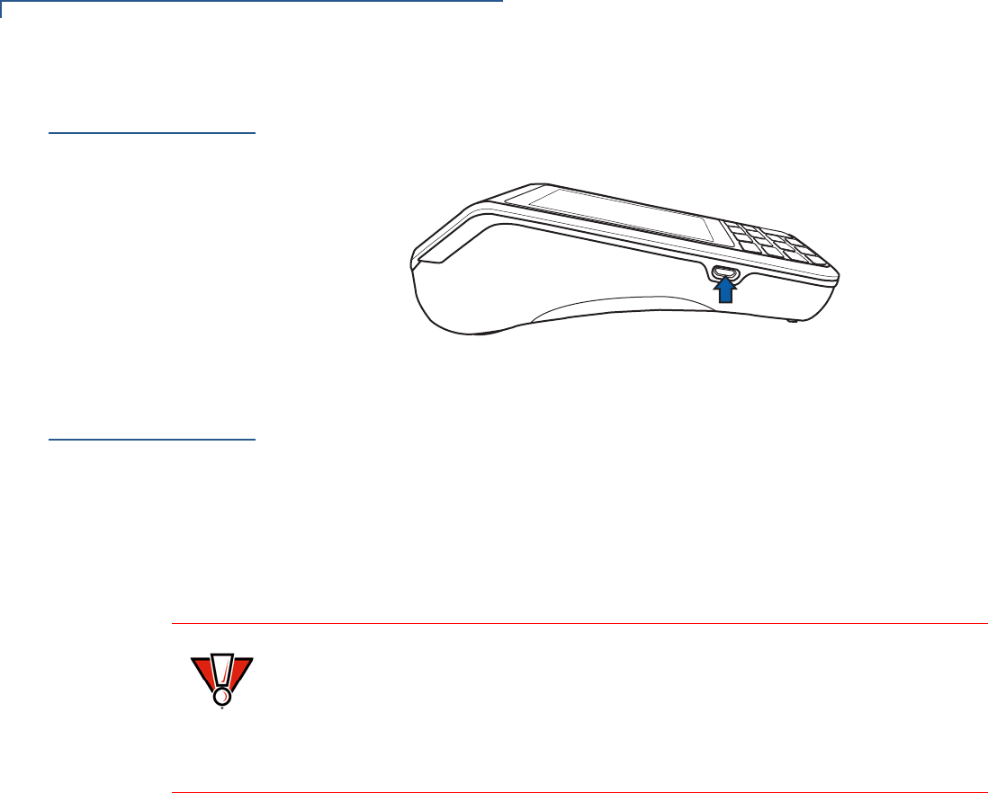
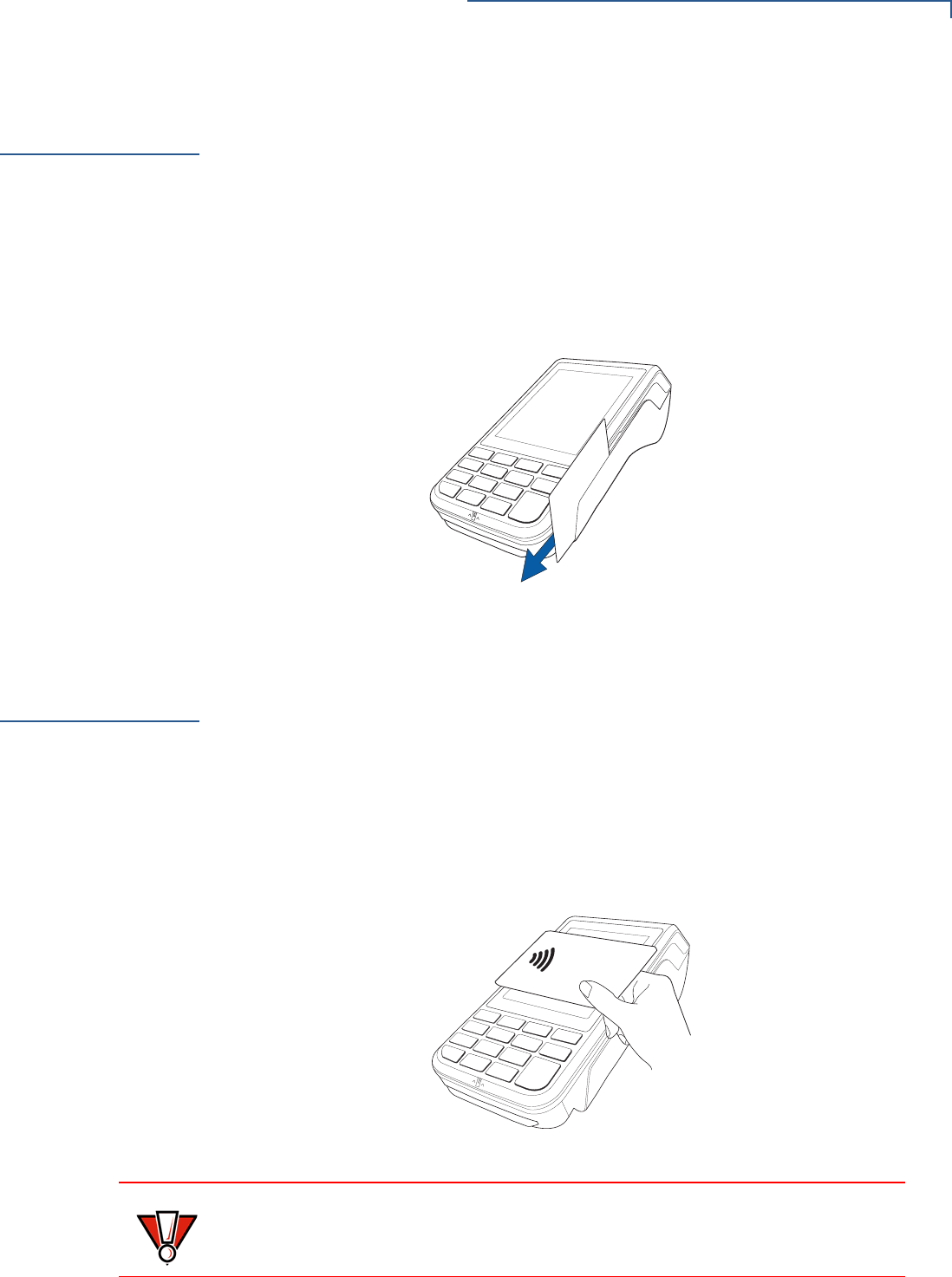
Printer Paper
Jam
If paper jams inside the printer:
•Press the button at the bottom of the terminal to unlatch the paper roll cover,
then open the cover.
•Remove the damaged paper from the paper roll and clear the feed
mechanism.
•Install a roll of printer paper.
•If the problem persists, it may be due to poor paper quality. Install a new roll of
higher-quality paper.
WARNING
Poor-quality paper may jam the printer. Refer to Accessories and Documentation
to order high-quality Verifone paper.

TROUBLESHOOTING GUIDELINES
Keypad Does Not Respond
VX 685/VX 690 INSTALLATION GUIDE 47
Keypad Does
Not Respond
If the keypad does not respond properly:
•Check the terminal display. If it displays the wrong character or nothing at all
when you press a key, follow the steps outlined in Transactions Fail To
Process.
•Refer to the user documentation for that application if pressing a function key
does not perform the expected action to ensure you are entering data
correctly.
•Contact your local Verifone representative if the problem persists.
Transactions
Fail To Process
There are several possible reasons why the unit may not be processing
transactions. Use the following steps to troubleshoot failures.
Checking Magnetic
Card Reader
To check magnetic card reader:
1Perform a test transaction using one or more different magnetic stripe cards to
ensure the problem is not a defective card.
2Ensure that you are swiping cards properly (see Magnetic Card Reader).
3Process a transaction manually using the keypad instead of the card reader. If
the manual transaction works, the problem may be a defective card reader.
4Contact your local Verifone representative if the problem persists.
Checking Smart Card
Reader
To check smart card reader:
1Perform a test transaction using several different smart cards to ensure the
problem is not a defective card.
2Ensure that the card is inserted correctly (see Smart Card Reader).
3Ensure the MSAM cards are properly inserted in the slots and are properly
secured (see MSAM Card).
4Contact your local Verifone representative if the problem persists.

TROUBLESHOOTING GUIDELINES
Transactions Fail To Process
48 VX 685/VX 690 INSTALLATION GUIDE
VX 685/VX 690 INSTALLATION GUIDE 49
APPENDIX A
Battery Information
The terminal uses a high-capacity Lithium-ion battery pack. The internal logic of
the battery prevents both overcharging and undercharging (a fault condition in
which the battery level goes well below the minimum acceptable charge and the
battery becomes unusable).
Charging
The battery has a safety circuit to protect the Lithium-ion cells from overcharging
and over-discharging. If the battery is over-discharged, the safety circuit shuts
down the battery. Recharge the battery to restore operation.
Advantages
Lithium-ion batteries have numerous advantages over other types of rechargeable
batteries.
High energy density
Lithium-ion batteries have twice the energy density of standard nickel-cadmium
batteries. This means they can store more energy than other rechargeable
batteries.
Light weight
Lithium is the lightest metal enabling the manufacture of lightweight devices.
Long Life
Lithium-ion batteries require low maintenance. They do not exhibit memory
effects, thereby eliminating the need for scheduled cycling to prolong the battery
life.
Does Not Require Prolonged Initial Charging
Unlike their nickel-cadmium counterparts, lithium-ion batteries do not require
prolonged initial charging. A regular charge cycle is enough.
NOTE
The terminal operates on battery power or on power pack power. The battery
charger in the terminal remains active whenever the power pack is connected.
NOTE
The terminal automatically shuts off when the battery reaches the critically low
charge state. If this occurs, recharge the battery for a minimum of 30 minutes
before it can power the terminal. A safety circuit that has been discharged below
its critical state may take several recharge attempts to reset.

BATTERY INFORMATION
Charging
50 VX 685/VX 690 INSTALLATION GUIDE
Low Self-Discharge Rate
Lithium-ion batteries have a lower self-discharge rate compared to other types of
battery (the self-discharge rate for a lithium-ion battery is less than one-half of that
of a nickel-cadmium battery). This means that once they are charged, they will
retain their charge for a longer time than other types of rechargeable batteries.
Other battery types can lose anywhere from 1-5% of their charge per day,
(depending on the storage temperature) even if they are not installed in a terminal.
Lithium-ion batteries will retain most of their charge even after months of storage.
High Voltage Capacity
Lithium-ion batteries operate at higher voltages than other rechargeable batteries,
about 3.6 volts for lithium-ion versus 1.2 volts for nickel-metal-hydride or nickel-
cadmium batteries. This means a single cell can often be used rather than
multiple metal-hydride or nickel-cadmium cells.
Precautions
Observe the following precautions when handling lithium-ion batteries.
Aging Effects
Battery packs are subject to aging, even when they are not used.
•Aging leads to deterioration in capacity or battery life.
•Batteries fail after 2 or 3 years, or approximately 300 charge-discharge cycles.
•Chemicals may also affect the aging properties of batteries.
Transportation Restrictions
•It is illegal to ship fully charge batteries by air because they may cause
accidental explosions.
•Shipment of large quantities of lithium-ion batteries may be subject to
regulatory control.
Storage Precautions
•Do not fully charge batteries before storage. Keep the batteries partially
charged before storing them, then charge them fully before actual usage.
TIP
Storing the battery in a cool environment (25 °C or less) at 40% charge reduces
the effects of aging.
NOTE
These precautions do not apply to personal carry-on battery packs.

BATTERY INFORMATION
Notable Battery Specifications
VX 685/VX 690 INSTALLATION GUIDE 51
•Do not store batteries when they are fully depleted. Charge an empty battery
for at least one hour before storage. When a depleted battery self discharges,
it may become unusable.
•Do not stock pile batteries. Avoid buying dated battery stocks even at reduced
prices. Always check the date when the batteries were manufactured.
Notable Battery
Specifications
The battery is designed to offer optimum protection to the terminals and their
users.
Safety/Protection
Circuit
The battery features a safety/protection circuit that provides the following benefits:
•Limits the peak voltage in each cell during charging – a field effect transistor
(FET) opens if voltage level in any cell reaches 4.28 V.
•Prevents cell voltage from dropping too low during discharge – a field effect
transistor (FET) opens if voltage in any cell reaches 2.3 V.
•Limits the current going in and coming out of the battery pack. A field effect
transistor (FET) opens the current path when charge current exceeds 6.5 A or
when the discharge current exceeds 7 A. This prevents damage caused by
shorting the battery contacts.
Cell Temperature
Monitoring
A discrete thermistor is built into the battery pack to prevent cell or terminal
damage during charging. The terminal’s OS monitors the cell temperature using
the thermistor and automatically shuts down the charger if the temperature
exceeds 50°C or falls below 0°C.
ESD Protection
Electrostatic discharge (ESD) protection: ±8 KV air discharge, ±4 KV contact
discharge
Trip Recovery
The battery features a trip recovery system, which resolves faulty or hazardous
conditions that led to a safety trip. Application of current through the charger
resets the safety circuit.
Battery FAQs
Should I allow the battery to discharge completely before charging?
No. It is better to recharge the battery often and avoid frequent full discharge.
However, allow a full discharge once a month to enable reset.
Should I charge the battery partially or fully?
It does not matter whether you charge the battery fully or partially. Charging a full
battery will not harm the battery.
WARNING
Do not dispose of batteries in a fire. Lithium-ion batteries must be
recycled or disposed of properly. Do not dispose of Lithium-ion
batteries in municipal waste sites.

BATTERY INFORMATION
Battery Specific Terms and Definitions
52 VX 685/VX 690 INSTALLATION GUIDE
Should I charge the battery before putting it into storage?
It is advisable to store the battery with a 40% charge. However, storing the battery
in a cool place is more important than the state of charge. Make sure the battery is
not fully depleted before storage otherwise, the safety/protection circuit may trip.
Will the battery heat up during charging?
It is normal for the battery to emit a small amount of heat during charging. The
battery is equipped with a temperature sensor that will disrupt the flow of charge
current when extreme temperature levels are detected.
Battery Specific
Terms and
Definitions
The following terms and definitions apply to the terminal’s battery.
Percent of Charge (%)
The ratio of the RC (remaining charge) value to the FC (full charge = 2450 mAh)
value multiplied by 100%. The range is from 0 to 100.
The Percent of Change value is available to terminal applications via OS calls. It is
updated every 20 seconds.
Remaining Charge (RC)
The amount of usable energy in the battery at a given time in mAh. The OS writes
RC=FC at the end of charge. The range is from 0 to FC.
The RC value is available to terminal applications via OS calls. It is updated every
20 seconds.
Safety/Protection Circuit
The terminal is equipped with a safety/protection circuit that protects the terminal
from damage. For more information, see Safety/Protection Circuit.
Voltage
Under system load, the terminal reports battery pack voltage. The range is from
3 V to 4.2 V. It is updated every 20 seconds.
General Battery
Terms and
Definitions
The following terms and definitions apply to most battery types, in general.
Ampere-hour, Amp-hour (Ah)
A unit of electrical energy. It is the specified current flowing for one hour. Two
ampere-hour is two amps of current flowing for one hour.
NOTE
The recommended operating temperature for the terminal is from 0°C to 50°C
(32°F to 122°F).

BATTERY INFORMATION
General Battery Terms and Definitions
VX 685/VX 690 INSTALLATION GUIDE 53
Battery Cell
The battery cell is the basic electrochemical unit used to store energy. Each cell is
typically rated 3.7 V. The terminal uses one lithium-ion rechargeable cell per
battery pack.
Battery Pack
A battery pack is an assembly of battery cells, safety circuit, temperature sensor,
terminal contacts, and plastic case.
Battery Status, State of Charge
This refers to the amount of electrical charge stored in the battery, expressed as a
percentage of the difference between the fully-charged and fully-discharged
states.
Capacity
This refers to the amount of available energy in a fully charged battery, expressed
in ampere-hours (Ah) or milliampere hours (mAh).
Charge
The amount of usable electrical energy stored in the battery, expressed in
coulombs.
Charge Rate
This refers to the amount of current applied to the battery during charging.
Charge Time
The amount of time required to charge a battery. Maximum charge time refers to
the amount of time to fully charge a fully discharged battery.
TIP
The capacity of terminal's high capacity battery pack is 2450 mAh typical (new).
NOTE
Charge rate for the terminal's battery: Initially 1 A tapering to zero at end of
charge.
NOTE
Typical charge time for the terminal’s battery: 2450 mAh in approximately 3.33
hours.

BATTERY INFORMATION
General Battery Terms and Definitions
54 VX 685/VX 690 INSTALLATION GUIDE
Charging
Refers to the process of converting electrical energy, in the form of electric
current, from an external source (charger) into chemical energy within a battery
cell.
Current
The flow of electrons through a conductor, measured in amperes
Cycle
This refers to the number of charge/discharge cycles the battery can endure
before it loses its ability to store useful charge.
Dead Battery
A battery is considered “dead” when it deep discharges to the point that it can no
longer accept a charge or when it has reached the end of its cycle life.
Deep Discharge
The state of a battery that has been discharged well below its useful charge level.
When a battery is in this state, it may be difficult to recharge. This characteristic
indicates a reduced cycle life.
Discharge Time, Run Time
This refers to the amount of time a battery can provide power to a system before it
discharges fully. It is a function of the load that receives power from the battery.
Discharging
Refers to the process of converting the chemical energy of a battery into electrical
energy, and the transfer of the electrical energy into a load.
Self-Discharge Rate
The amount by which the charge of the battery is reduced without providing any
current to an external terminal or load.
NOTE
The terminal’s battery pack retains approximately 70% of its original charge after
300 cycles.

BATTERY INFORMATION
General Battery Terms and Definitions
VX 685/VX 690 INSTALLATION GUIDE 55
Shelf-Life
The length of storage under specified conditions that a battery can endure while
retaining the ability to give a satisfactory performance upon full charge.
Voltage
This is the unit of potential power or electric pressure, which is the force that
causes current to flow through an electric conductor. It is measured in volts.
NOTE
The shelf life of the terminal battery pack is 6 months at 30% initial charge.