Verifone VX805CTLS POS Terminal User Manual USERS MANUAL
VeriFone Inc POS Terminal USERS MANUAL
UserManual.wiki
>
Verifone
>
VX805CTLS User Manual
Users Manual
Navigation menu
Upload a User Manual
Namespaces
Wiki Guide
HTML
PDF
Info
Views
User Manual
Discussion / Help
Navigation
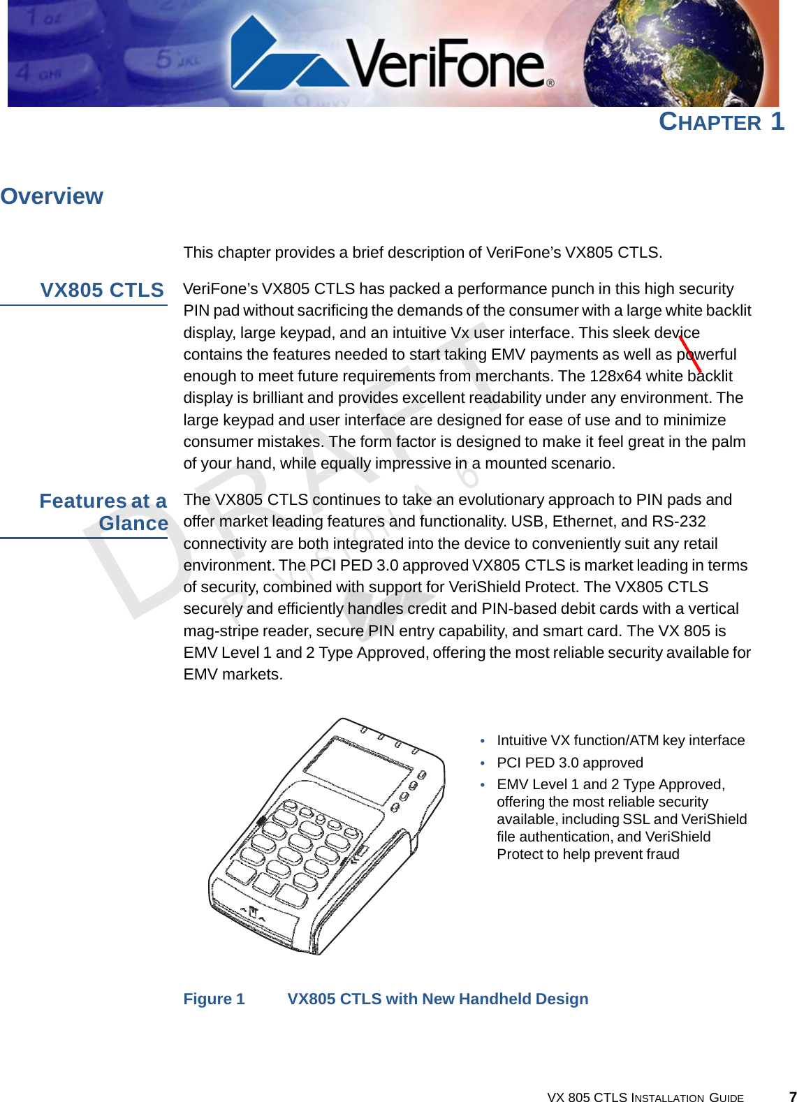
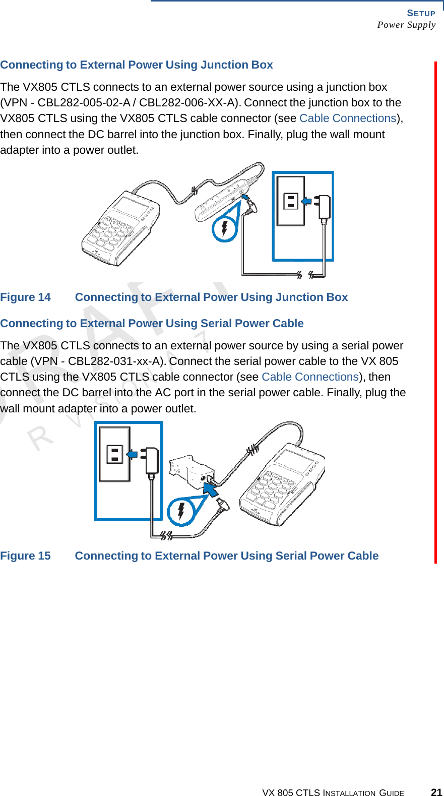
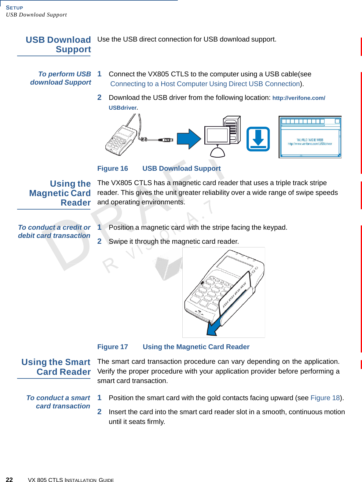
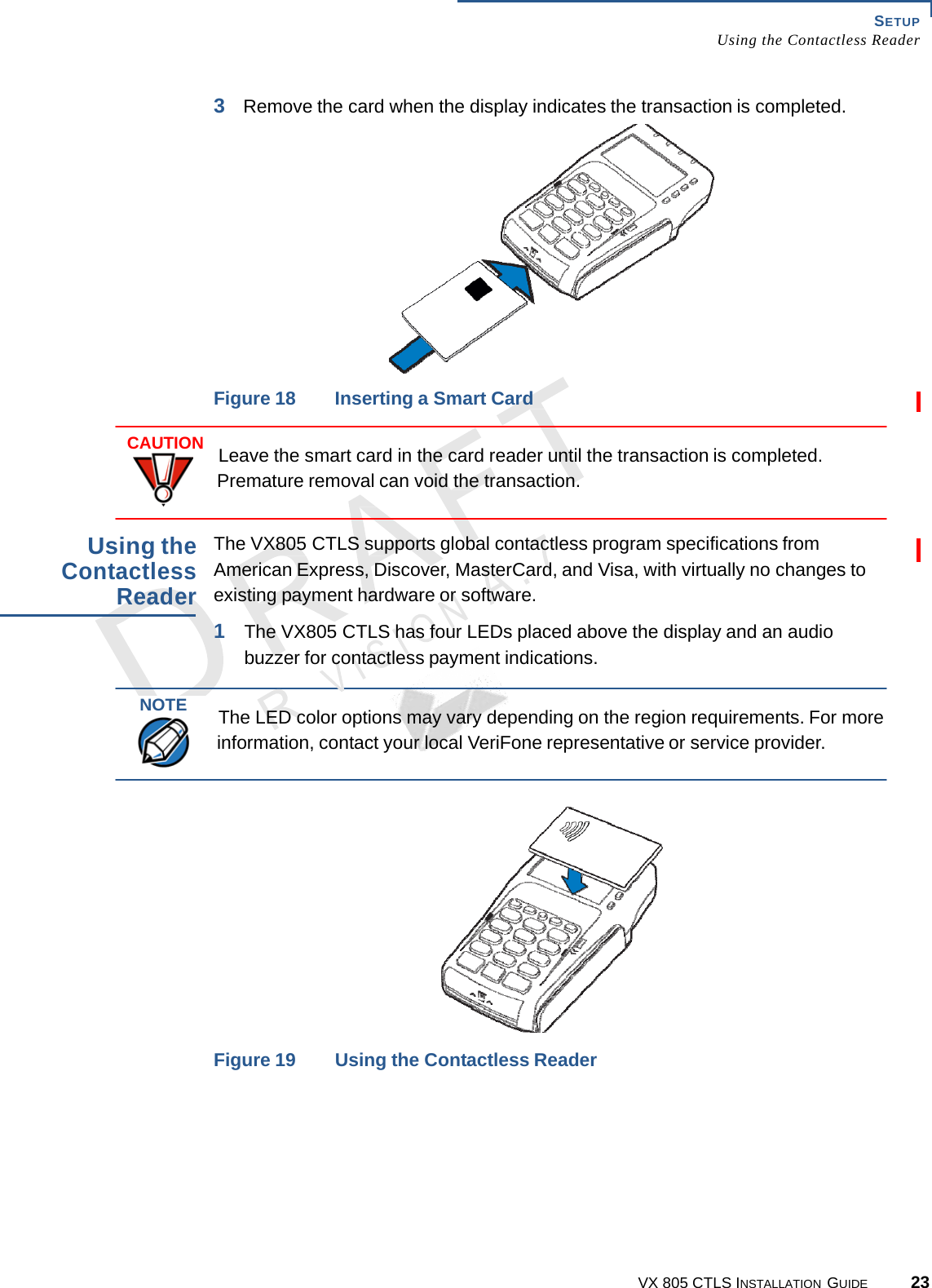
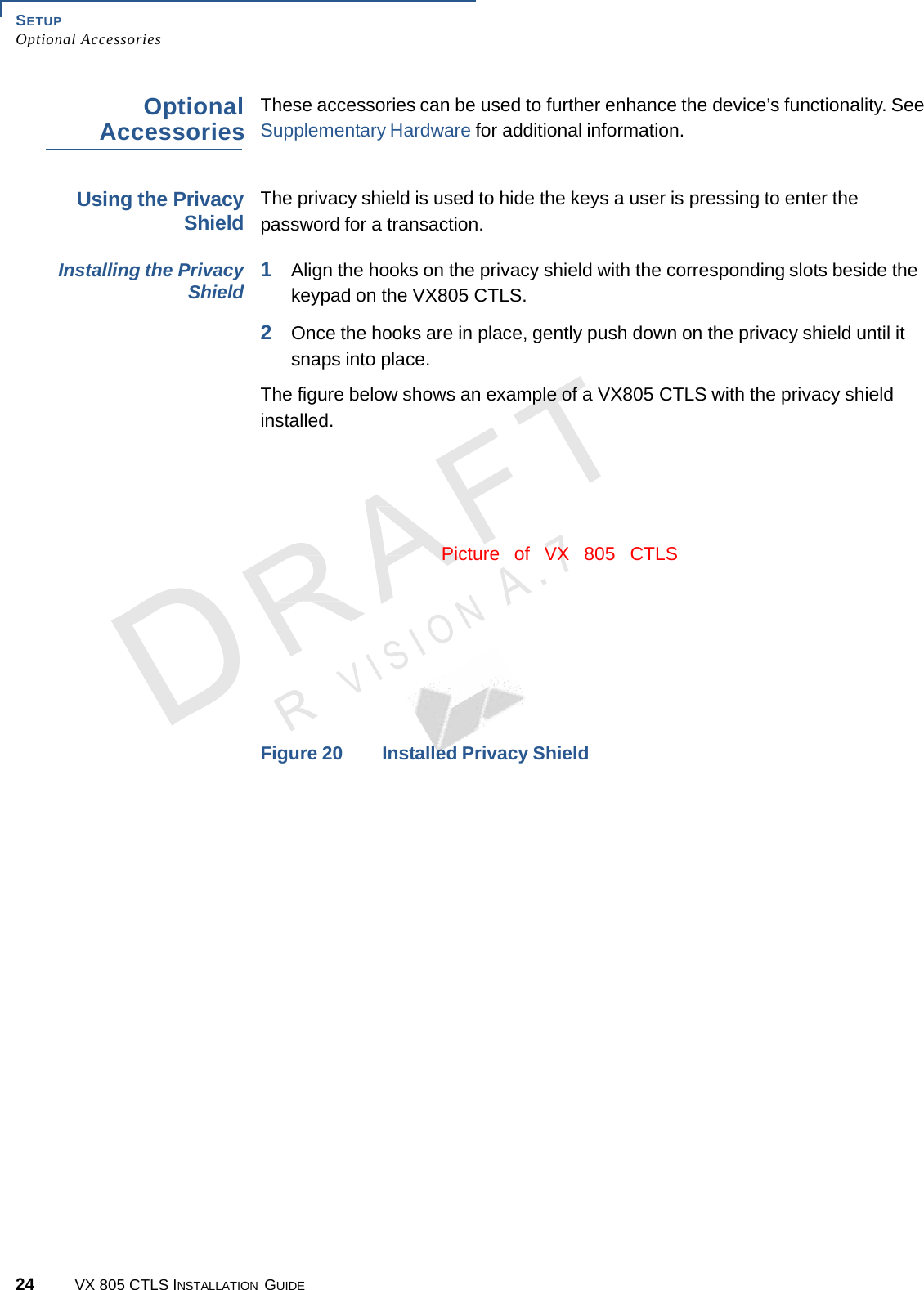
![12 VX 805 CTLS INSTALLATION GUIDE SETUP Examining Device Features A.7 N Examining Device Features Before you continue with the installation process, familiarize yourself with the VX805 CTLS features: LEDS FOR CONTACTLESS SUPPORT LCD/CTLS DISPLAY TELCO KEYPAD ATM STYLE KEYS MAGNETIC CARD READER COLOR-CODED FUNCTION KEYS SMART CARD READER Figure 2 VX805 CTLS Features The VX805 CTLS includes the following features: • An LCD display. • Three color-coded function keys below the keypad (CANCEL [RED], BACKSPACE [YELLOW], ENTER [GREEN]). • A magnetic card reader, built into the right side. An icon shows the proper swipe direction, with the stripe facing down and towards the keypad. • A smart card reader, built into the unit’s front side. An icon indicates the proper card position and insertion direction. • A SAM (Security Access Module) compartment, built into the back side of the unit. The VX805 CTLS contains multiple-SAM (MSAM) cardholders to support multiple stored-value card programs or other merchant card requirements. • Contactless (CTLS) payment support.](https://usermanual.wiki/Verifone/VX805CTLS/User-Guide-1744514-Page-14.png)