Verifone VX805CTLS POS Terminal User Manual USERS MANUAL
VeriFone Inc POS Terminal USERS MANUAL
Verifone >
Users Manual
A
.
7
I
O
N
VI
S
V
X 805 CTLS
VX805 CTLS
Installation Guide
VeriFone Part Number DOC280-023-EN-A, Revision A.7

VX805 CTLS Installation
Guide
© 2012 VeriFone,
Inc.
All rights reserved. No part of the contents of this document may be reproduced or transmitted in any form without the written
permission of VeriFone, Inc.
The information contained in this document is subject to change without notice. Although VeriFone has attempted to ensure the
accuracy of the contents of this document, this document may include errors or omissions. The examples and sample programs are
for illustration only and may not be suited for your purpose. You should verify the applicability of any example or sample program
before placing the software into productive use. This document, including without limitation the examples and software programs, is
supplied “As-Is.”
VeriFone, the VeriFone logo, Omni, VeriCentre, Verix, and ZonTalk are registered trademarks of VeriFone. Other brand
names or trademarks associated with VeriFone’s products and services are trademarks of VeriFone, Inc.
All other brand names and trademarks appearing in this manual are the property of their respective holders.
Comments? Please e-mail all comments in this document to your local VeriFone Support Team.
VeriFone,
Inc.
2099 Gateway Place, Suite
600
San Jose, CA, 95110
USA
www.verifone.com
VeriFone Part Number DOC280-023-EN-A, Revision
A.7

1
VX 805 CTLS INSTALLATION G
UIDE
C
ONTENTS
P
RE
FA
CE . . . . . . . . . . . . . . . . . . . . . . . . . . . . . . . . . . . . . . . 3
Audience. . . . . . . . . . . . . . . . . . . . . . . . . . . . . . . . . . . . . . . . . . . . . . . . . . . . . . . . 3
Organization
. . . . . . . . . . . . . . . . . . . . . . . . . . . . . . . . . . . . . . . . . . . . . . . . . . . . . 3
Related Documentation . . . . . . . . . . . . . . . . . . . . . . . . . . . . . . . . . . . . . . . . . . . . 3
Guide
Conventions
. . . . . . . . . . . . . . . . . . . . . . . . . . . . . . . . . . . . . . . . . . . . . . . . 4
Acronym Definitions . . . . . . . . . . . . . . . . . . . . . . . . . . . . . . . . . . . . . . . . . . . . 5
C
H
A
PT
ER 1
Overview VX805 CTLS . . . . . . . . . . . . . . . . . . . . . . . . . . . . . . . . . . . . . . . . . . . . . . . . . . . . 7
Features at a Glance . . . . . . . . . . . . . . . . . . . . . . . . . . . . . . . . . . . . . . . . . . . . . . 7
Features and Benefits . . . . . . . . . . . . . . . . . . . . . . . . . . . . . . . . . . . . . . . . . . . . . 8
C
H
A
PT
ER 2
Setup Selecting a
Location
. . . . . . . . . . . . . . . . . . . . . . . . . . . . . . . . . . . . . . . . . . . . . . . 9
Ease of Use . . . . . . . . . . . . . . . . . . . . . . . . . . . . . . . . . . . . . . . . . . . . . . . . . . 9
Environmental Factors . . . . . . . . . . . . . . . . . . . . . . . . . . . . . . . . . . . . . . . . . 10
Electrical Considerations . . . . . . . . . . . . . . . . . . . . . . . . . . . . . . . . . . . . . . . 11
Unpacking the Shipping Carton . . . . . . . . . . . . . . . . . . . . . . . . . . . . . . . . . . . . . 11
Examining Device
Features . . . . . . . . . . . . . . . . . . . . . . . . . . . . . . . . . . . . . . . . . . . . . . . . . . . . . . . 12
Opening and Replacing Card and Connector Compartment . . . . . . . . . . . . . . . 13
Installing and Replacing MSAM
Cards
. . . . . . . . . . . . . . . . . . . . . . . . . . . . . . . . 14
Cable
Connections
. . . . . . . . . . . . . . . . . . . . . . . . . . . . . . . . . . . . . . . . . . . . . . . 15
Attaching a Cable Connector to the VX805 CTLS . . . . . . . . . . . . . . . . . . . . 15
External Device Connections . . . . . . . . . . . . . . . . . . . . . . . . . . . . . . . . . . . . . . . 15
Connecting to Another VeriFone Terminal . . . . . . . . . . . . . . . . . . . . . . . . . . 16
Connecting to a Host Computer . . . . . . . . . . . . . . . . . . . . . . . . . . . . . . . . . . 17
Connecting to an Ethernet Port. . . . . . . . . . . . . . . . . . . . . . . . . . . . . . . . . . . 18
Connecting to an ECR . . . . . . . . . . . . . . . . . . . . . . . . . . . . . . . . . . . . . . . . . 19
Power Supply . . . . . . . . . . . . . . . . . . . . . . . . . . . . . . . . . . . . . . . . . . . . . . . . . . . 20
Power
Connections
. . . . . . . . . . . . . . . . . . . . . . . . . . . . . . . . . . . . . . . . . . . . 20
USB Download Support . . . . . . . . . . . . . . . . . . . . . . . . . . . . . . . . . . . . . . . . . . . 22
Using the Magnetic Card
Reader
. . . . . . . . . . . . . . . . . . . . . . . . . . . . . . . . . . . . 22
Using the Smart Card Reader . . . . . . . . . . . . . . . . . . . . . . . . . . . . . . . . . . . . . . 22
Using the Contactless Reader . . . . . . . . . . . . . . . . . . . . . . . . . . . . . . . . . . . . . . 23
Optional Accessories . . . . . . . . . . . . . . . . . . . . . . . . . . . . . . . . . . . . . . . . . . . . . 24
Using the Privacy
Shield
. . . . . . . . . . . . . . . . . . . . . . . . . . . . . . . . . . . . . . . . 24
C
H
A
PT
ER 3
Specifications Unit Power
Requirements
. . . . . . . . . . . . . . . . . . . . . . . . . . . . . . . . . . . . . . . 25
Power
Pack
. . . . . . . . . . . . . . . . . . . . . . . . . . . . . . . . . . . . . . . . . . . . . . . . . . 25
Temperature . . . . . . . . . . . . . . . . . . . . . . . . . . . . . . . . . . . . . . . . . . . . . . . . . 25
External
Dimensions
. . . . . . . . . . . . . . . . . . . . . . . . . . . . . . . . . . . . . . . . . . . 25
Weight
. . . . . . . . . . . . . . . . . . . . . . . . . . . . . . . . . . . . . . . . . . . . . . . . . . . . . . 25
Processor . . . . . . . . . . . . . . . . . . . . . . . . . . . . . . . . . . . . . . . . . . . . . . . . . . . 25
Memory
. . . . . . . . . . . . . . . . . . . . . . . . . . . . . . . . . . . . . . . . . . . . . . . . . . . . . 25

2 VX 805 CTLS INSTALLATION G
UIDE
Display . . . . . . . . . . . . . . . . . . . . . . . . . . . . . . . . . . . . . . . . . . . . . . . . . . . . . 25
Magnetic Card Reader . . . . . . . . . . . . . . . . . . . . . . . . . . . . . . . . . . . . . . . . . 25
Primary Smart Card . . . . . . . . . . . . . . . . . . . . . . . . . . . . . . . . . . . . . . . . . . . 25
SAM Card Reader. . . . . . . . . . . . . . . . . . . . . . . . . . . . . . . . . . . . . . . . . . . . . 25
CTLS Card
Reader
. . . . . . . . . . . . . . . . . . . . . . . . . . . . . . . . . . . . . . . . . . . . 26
Keypad . . . . . . . . . . . . . . . . . . . . . . . . . . . . . . . . . . . . . . . . . . . . . . . . . . . . . 26
Peripheral Ports . . . . . . . . . . . . . . . . . . . . . . . . . . . . . . . . . . . . . . . . . . . . . . 26
Security
. . . . . . . . . . . . . . . . . . . . . . . . . . . . . . . . . . . . . . . . . . . . . . . . . . . . . 26
C
HA
PTE
R 4
Maintenance and
Cleaning
Additional Safety Information . . . . . . . . . . . . . . . . . . . . . . . . . . . . . . . . . . . . . . . 28
Power Adapter . . . . . . . . . . . . . . . . . . . . . . . . . . . . . . . . . . . . . . . . . . . . . . . 28
Potentially Explosive Environments . . . . . . . . . . . . . . . . . . . . . . . . . . . . . . . 28
Card Readers . . . . . . . . . . . . . . . . . . . . . . . . . . . . . . . . . . . . . . . . . . . . . . . . 28
C
HA
PTE
R 5
Service and Support Service Returns . . . . . . . . . . . . . . . . . . . . . . . . . . . . . . . . . . . . . . . . . . . . . . . . . 29
Accessories and Documentation . . . . . . . . . . . . . . . . . . . . . . . . . . . . . . . . . . . . 31
Supplementary
Hardware
. . . . . . . . . . . . . . . . . . . . . . . . . . . . . . . . . . . . . . . 31
Data Cables . . . . . . . . . . . . . . . . . . . . . . . . . . . . . . . . . . . . . . . . . . . . . . . . . 31
Power Supply . . . . . . . . . . . . . . . . . . . . . . . . . . . . . . . . . . . . . . . . . . . . . . . . 31
C
HA
PTE
R 6
Troubleshooting
Guidelines
PIN Pad Does Not Start . . . . . . . . . . . . . . . . . . . . . . . . . . . . . . . . . . . . . . . . . . . 33
Blank Display . . . . . . . . . . . . . . . . . . . . . . . . . . . . . . . . . . . . . . . . . . . . . . . . . . . 33
Keypad Does Not Respond . . . . . . . . . . . . . . . . . . . . . . . . . . . . . . . . . . . . . . . . 34
Transactions Fail To
Process
. . . . . . . . . . . . . . . . . . . . . . . . . . . . . . . . . . . . . . . 34

3
VX 805 INSTALLATION G
UIDE
VX 805 CTLS Certifications and Regulations Sheet VPN - DOC280-021-EN-A
VX 805 CTLS Quick Installation Guide VPN - DOC280-022-EN-A
VX 805 CTLS Reference Guide VPN - DOC280-024-EN-A
VX 805 CTLS Programmer’s Guide VPN - DOC280-025-EN-A
Verix eVo Volume I: Operating System
Programmers Manual VPN - DOC00301
Verix eVo Volume II: Operating System and
Communication Programmers Manual VPN - DOC00302
Verix eVo Volume III: Operating System
Programming Tools Reference Manual VPN - DOC00303
P
REFACE
This guide is the primary source of information for setting up and installing the
VX805 CTLS.
Audience This guide describes the VX805 CTLS features, and provides the basic
information for its installation and configuration.
Organization This guide is organized as
follows:
Chapter 1, Overview. Provides an overview of the VX805 CTLS.
Chapter 2, Setup. Explains setup and installation of the VX805 CTLS, selecting a
location, and establishing connections with other devices.
Chapter 3, Specifications. Discusses power requirements and dimensions of the
VX805 CTLS.
Chapter 4, Maintenance and Cleaning. Explains maintenance of the VX 805
CTLS.
Chapter 5, Service and Support. Provides information on contacting your
VeriFone service provider and information on how to order accessories or
documentations from VeriFone.
Chapter 6, Troubleshooting Guidelines. Provides troubleshooting guidelines
should you encounter a problem in terminal installation and configuration.
Related
Documentation
To learn more about the VX805 CTLS, refer to the following set of documents:
P
REFACE
Guide Conventions
4 VX 805 CTLS INSTALLATION G
UIDE
.
6
Guide
Conventions
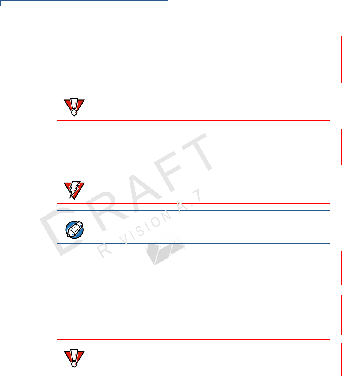
Various conventions are used to help you quickly identify special formatting.
Table 1 describes these conventions and provides examples of their use.
Table 1 Document Conventions
Convention Meaning Example
Blue Text in blue indicates terms that
are cross referenced.
See Guide Conventions.
Italics Italic typeface indicates book
titles or emphasis.
You must not use this unit
underwater.
NOTE
The pencil icon is used to
highlight important information.
RS-232-type devices do not work
with the PIN pad port.
CAUTION
The caution symbol indicates
possible hardware or software
failure, or loss of data.
The device is not waterproof or
dustproof, and is intended for
indoor use only.
WARNING The lightning symbol is used as
a warning when bodily injury
might occur.
Due to risk of shock do not use the
device near water.

5
VX 805 INSTALLATION G
UIDE
6
A
.
N
O
I
S
I
E
V
R
P
REFACE
Guide Conventions
Acronym Definitions Various acronyms are used in place of the full definition. Table 2 presents
acronyms and their definitions.
Table 2 Acronym
Definitions
Acronym Definitions
3DES Triple Data Encryption Standard
AES Advanced Encryption Standard Algorithm
CTLS Contactless
DES Data Encryption Standard
DUKPT Derived Unique Key Per Transaction Method as defined in the
VISA’s POS Equipment Requirement: PIN processing and Data
Authentication, International Version 1.0, August 1988
ECR Electronic Cash Register
EMV Joint Europay, MasterCard and Visa Standard
LED Light-Emitting Diode
LCD Liquid Crystal Display
MSAM Multiple Secure Access Module
OS Operating System
PED PIN Entry Device
PIN Personal Identification Number
POS Point-of-Sale
SAM Secure Access Module
SC Smart Card (Integrated Chip Card)
SD Secure Digital
SR Ship Release
UI User Interface
USB Universal Serial Bus

6
P
REFACE
Guide Conventions
A
.
6
O
N
S
I
R
E
V
I
VX 805 CTLS INSTALLATION G
UIDE
NOTE
This equipment has been tested and found to comply with the limits for a
Class B digital device, pursuant to Part 15 of the FCC Rules. These limits are designed
to provide reasonable
protection against harmful interference in a residential installation. This equipment
generates, uses and can radiate
radio frequency energy and, if not installed and used in accordance with the instructions,
may cause harmful
interference to radio communications. However, there is no guarantee that interference
will not occur in a particular
installation. If this equipment does cause harmful interference to radio or television
reception,
which can be determined by turning the equipment off and on, the user is encouraged to
try to correct the
interference by one or more of the following measures:
-- Reorient or relocate the receiving antenna.
-- Increase the separation between the equipment and receiver.
-- Connect the equipment into an outlet on a circuit different from that to which the
receiver is connect
-- Consult the dealer or an experienced radio/TV technician for help.
15.21 “Changes or modifications are not expressly
approved by the manufacturer could void the user's authority to operate the equipment.”
-English:"This device complies with Industry Canada licence-exempt RSS and part 15 of
the FCC rules standard(s). Operation is
subject to the following two conditions: (1) this device may not cause interference, and
(2) this device must accept
any interference, including interference that may cause undesired operation of the
device."
- French:"Le présent appareil est conforme aux CNR d'Industrie Canada applicables aux
appareils radio exempts de
licence. 'exploitation est autorisée aux deux conditions suivantes : (1) l'appareil ne doit
pas produire de brouillage, et
(2) l'utilisateur de l'appareil doit accepter tout brouillage radioélectrique subi, même si le
brouillage est susceptible
d'en compromettre le fonctionnement."
This device complies with part 15 of the FCC Rules. Operation is subject to the following
two conditions:
(1) This device may not cause harmful interference, and (2) this device must accept any
interference received,
including interference that may cause undesired operation
CHAPTER 1
7
VX 805 CTLS INSTALLATION G
UIDE
Overview
This chapter provides a brief description of VeriFone’s VX805 CTLS.
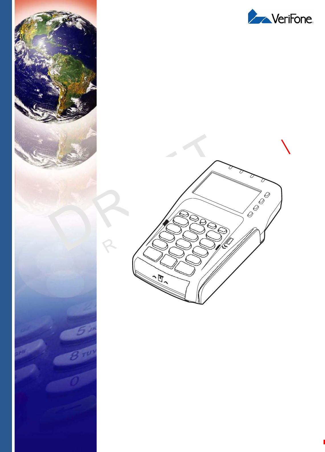
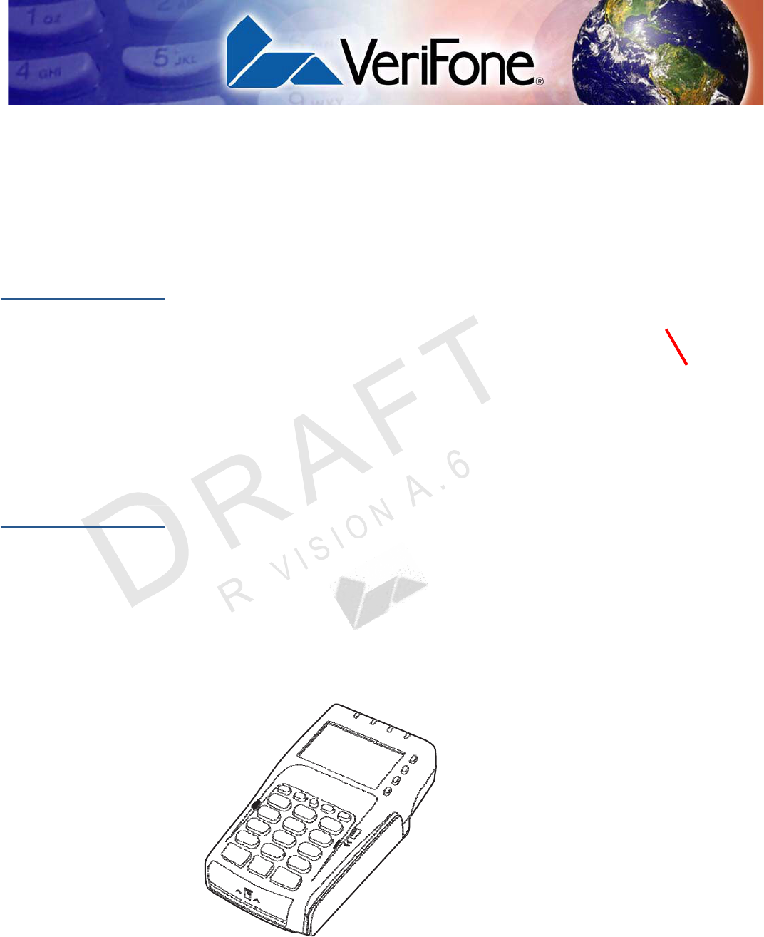
VX805 CTLS VeriFone’s VX805 CTLS has packed a performance punch in this high security
PIN pad without sacrificing the demands of the consumer with a large white backlit
display, large keypad, and an intuitive Vx user interface. This sleek device
contains the features needed to start taking EMV payments as well as powerful
enough to meet future requirements from merchants. The 128x64 white backlit
display is brilliant and provides excellent readability under any environment. The
large keypad and user interface are designed for ease of use and to minimize
consumer mistakes. The form factor is designed to make it feel great in the palm
of your hand, while equally impressive in a mounted scenario.
Features at a
Glance
The VX805 CTLS continues to take an evolutionary approach to PIN pads and
offer market leading features and functionality. USB, Ethernet, and RS-232
connectivity are both integrated into the device to conveniently suit any retail
environment. The PCI PED 3.0 approved VX805 CTLS is market leading in terms
of security, combined with support for VeriShield Protect. The VX805 CTLS
securely and efficiently handles credit and PIN-based debit cards with a vertical
mag-stripe reader, secure PIN entry capability, and smart card. The VX 805 is
EMV Level 1 and 2 Type Approved, offering the most reliable security available for
EMV markets.
• Intuitive VX function/ATM key interface
• PCI PED 3.0 approved
• EMV Level 1 and 2 Type Approved,
offering the most reliable security
available, including SSL and VeriShield
file authentication, and VeriShield
Protect to help prevent fraud
Figure 1 VX805 CTLS with New Handheld Design

10 VX 805 CTLS INSTALLATION G
UIDE
O
VERVIEW
Features and Benefits
Features and
Benefits
Exceptional Ease of Use
• Efficient, stylish, ergonomic design provides for convenient consumer
handling, minimizing user errors
• Intuitive telco-style interface with large, colored control keys simplify training
and reduce support requests
• Highly readable 128x64 white backlit display provides excellent usability and
handles multiple languages for global use
Critical Security Protection
• PCI PTS 3.0 approved
• Supports VeriShield Protect to encrypt and protect consumer card information
• Integrated security modules simultaneously support sophisticated encryption
(AES, DES, 3DES, RSA) and key management schemes, including single and
3DES Master Session, single, and 3DES Derived
Strong Feature Set
• Ensures uncompromising reliability from VeriFone, the worldwide leader in e-
payment
• Primary smart card reader support for synchronous and asynchronous smart
cards
• Support for international character sets and Unicode standard
• EMV Level 1 and Level 2 approved for smart card solutions
• Offers the most reliable security available, including SSL, VeriShield file
authentication, and VeriShield Protect to help prevent fraud and other
intrusions
Extended PIN Pad Capabilities
• Optional privacy shield
• Patent-pending MAXui design, highlighted by a 128x64 white backlit display
and large keypad, makes it easy to use under any lighting condition
• Triple-track, high-coercivity, bi-directional card reader handles most magnetic
stripe cards
• Up to two Security Access Modules (SAMs) safeguard sensitive financial data
and support multiple smart card schemes
• Can be powered by other Vx series terminals through a dual multi-port
connector which supports Ethernet, RS-232, and USB 2.0 devices

CHAPTER 2
9
VX 805 CTLS INSTALLATION G
UIDE
Setup
Selecting a
Location
This chapter describes the setup procedure for the VX805 CTLS, in the following
sections:
• Selecting a Location
• Unpacking the Shipping Carton
• Examining Device Features
• Opening and Replacing Card and Connector Compartment
• Installing and Replacing MSAM Cards
• Cable Connections
• External Device Connections
• Power Supply
• USB Download Support
• Using the Magnetic Card Reader
• Using the Smart Card Reader
• Using the Contactless Reader
• Optional Accessories
Use the following guidelines to select a location for the VX805 CTLS.
Ease of Use • Select a location convenient for both merchant and cardholder.
• Select a flat support surface, such as a countertop or table.
• Select a location near a power outlet and the terminal, ECR, or computer
connected to the VX805 CTLS. For safety, do not string cables or cords
across a walkway.
10 VX 805 CTLS INSTALLATION G
UIDE
S
ETUP
Selecting a Location
Environmental
Factors
• Do not use the unit where there is high heat, dust, humidity, moisture, or
caustic chemicals or oils.
• Keep the unit away from direct sunlight and anything that radiates heat, such
as a stove or a motor.
• Do not use the VX805 CTLS outdoors.
CAUTION
The VX805 CTLS is not waterproof or dustproof, and is intended for indoor use
only. Any damage to the unit from exposure to rain or dust can void any warranty.

11
VX 805 CTLS INSTALLATION G
UIDE
S
ETUP
Unpacking the Shipping Carton
Electrical
Considerations • Avoid using this product during electrical storms.
• Avoid locations near electrical appliances or other devices that cause
excessive voltage fluctuations or emit electrical noise (for example, air
conditioners, electric motors, neon signs, high-frequency or magnetic security
devices, or computer equipment).
• Do not use the VX805 CTLS near water or in moist conditions.
WARNING Due to risk of shock or damage, do not use the VX805 CTLS near water,
including a bathtub, wash bowl, kitchen sink or laundry tub, in a wet basement, or
near a swimming pool.
Unpacking
the
Shipping Carton
Open the shipping carton and carefully inspect its contents for possible tampering
or shipping damage. The VX805 CTLS is a secure product and any tampering can
cause it to cease to function or to operate in an unsecured manner.
1 Remove and inspect the contents of the shipping carton, since the VX 805
CTLS ships in multiple configurations, the carton may include any or all of the
following:
• VX805 CTLS
• Privacy shield
2 Remove all plastic wrapping from the terminal and components.
3 Remove the clear protective film from the display.
4 Save the shipping carton and packing material for future repacking or moving
of the device.
WARNING Do not use a unit that has been tampered with or damaged.
The VX805 CTLS comes equipped with tamper-evident labels. If a label or
component appears damaged, please notify the shipping company and your
VeriFone service provider immediately.
12 VX 805 CTLS INSTALLATION G
UIDE
S
ETUP
Examining Device Features
A
.
7
N
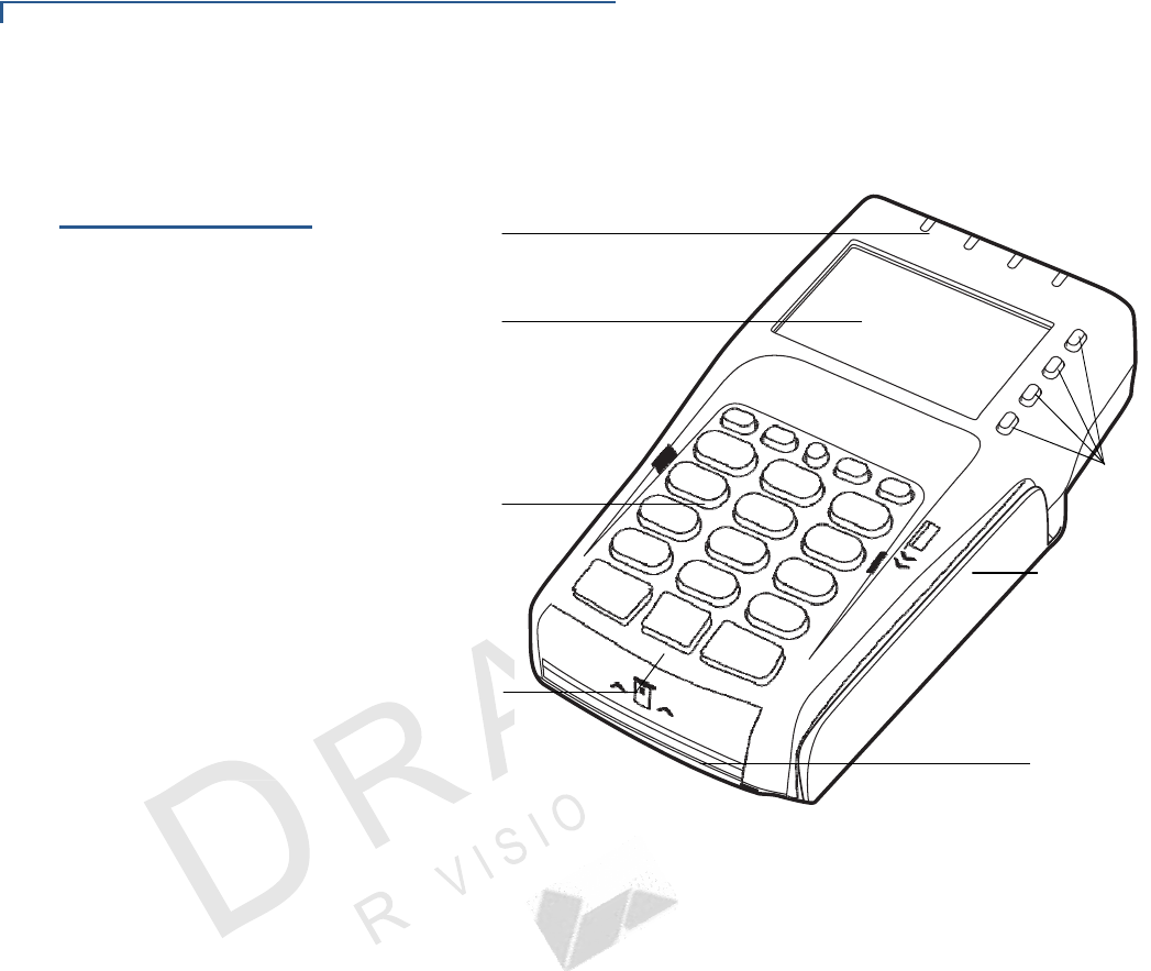
Examining
Device
Features
Before you continue with the installation process, familiarize yourself with the
VX805 CTLS features:
LEDS
FOR
CONTACTLESS
SUPPORT
LCD/CTLS
DISPLAY
TELCO
KEYPAD
ATM STYLE
KEYS
MAGNETIC CARD
READER
COLOR-CODED
FUNCTION KEYS
SMART CARD
READER
Figure 2 VX805 CTLS Features
The VX805 CTLS includes the following features:
• An LCD display.
• Three color-coded function keys below the keypad (CANCEL
[
RED
],
BACKSPACE [YELLOW], ENTER
[
GREEN
]).
• A magnetic card reader, built into the right side. An icon shows the proper
swipe direction, with the stripe facing down and towards the keypad.
• A smart card reader, built into the unit’s front side. An icon indicates the
proper card position and insertion direction.
• A SAM (Security Access Module) compartment, built into the back side
of the unit. The VX805 CTLS contains multiple-SAM (MSAM) cardholders
to support multiple stored-value card programs or other merchant card
requirements.
• Contactless (CTLS) payment support.
13
VX 805 CTLS INSTALLATION G
UIDE
S
ETUP
Opening and Replacing Card and Connector Compartment
A
.
7
O
N
S
I E
V
I
Opening
and
Replacing
Card
and
Connector
Compartment
To access the cable and MSAM compartment, you have to first remove the
compartment door.
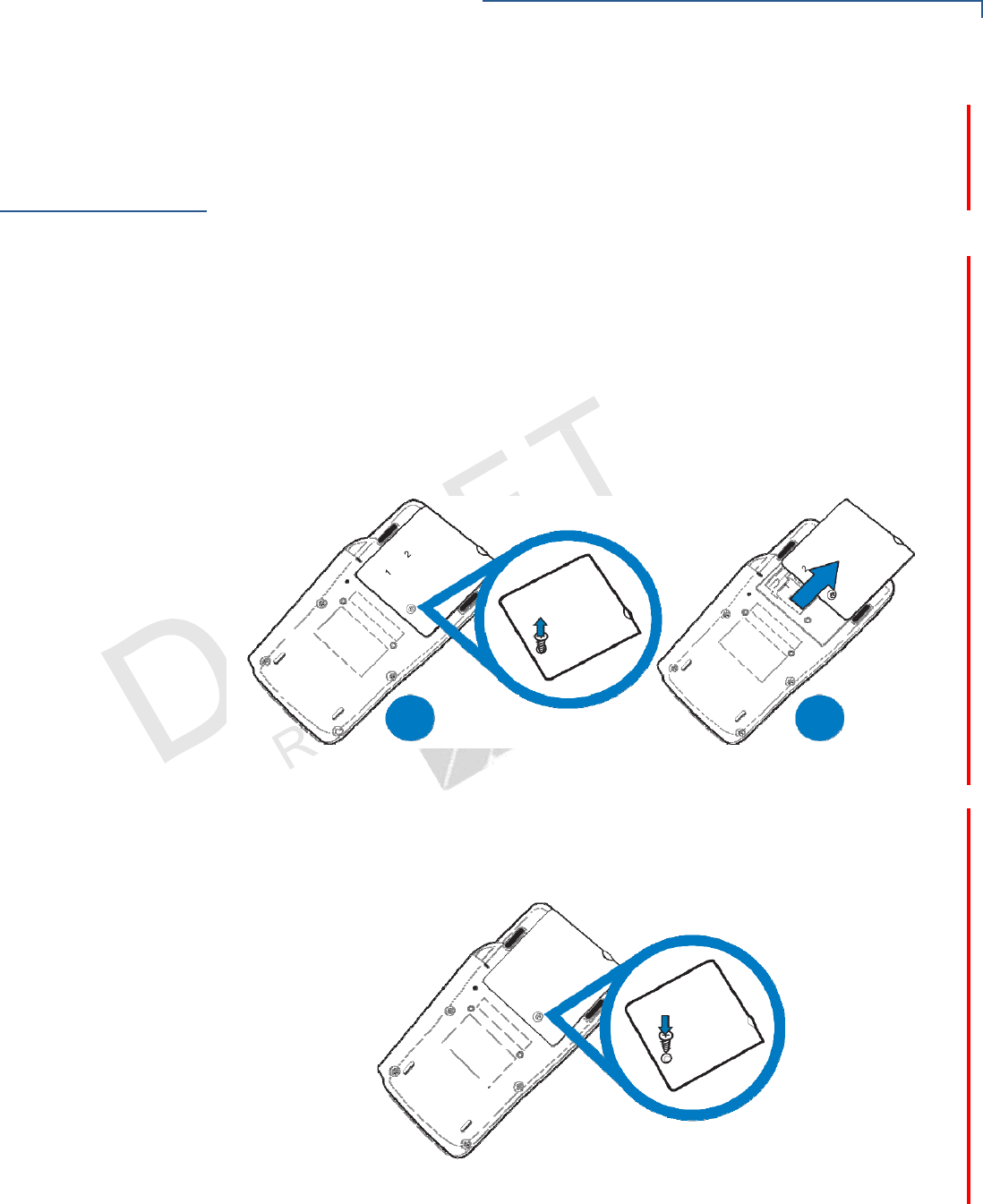
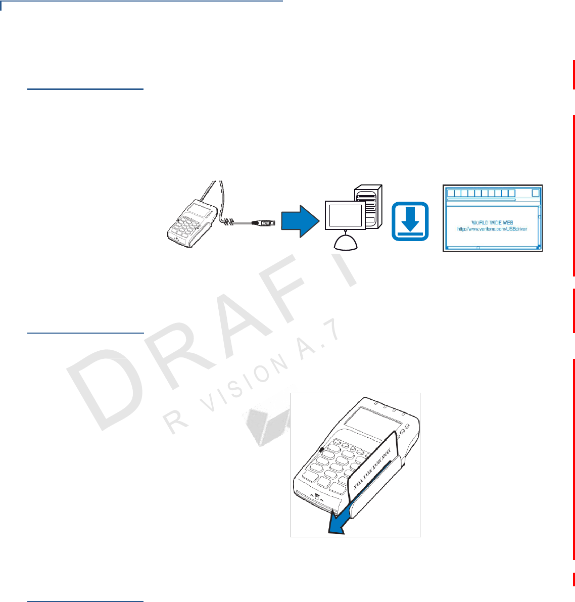
To open the
compartment door 1 Power off the VX805 CTLS unit.
2 Place the VX805 CTLS face down on a soft, clean surface to protect the lens
from scratches.
3 Loosen the retaining screw. The retaining screw is captive, which means that it
cannot be fully removed from the slot.
4 Slide out and lift the compartment door.
The cable connector and MSAM cardholders are now accessible.bered tray.
A
B
Figure 3 Opening Compartment Door
To replace the
compartment door 1 Close the compartment door after inserting or replacing the necessary cards
and cable.
2 Tighten locking screw.
Figure 4 Closing Compartment Door
14 VX 805 CTLS INSTALLATION G
UIDE
S
ETUP
Installing and Replacing MSAM Cards
Installing
and
Replacing
MSAM
Cards
You may need to install one or more multiple security access module (MSAM)
cards or replace the old cards.
CAUTION Observe standard precautions in handling electrostatically sensitive devices.
Electrostatic discharges can damage the equipment. VeriFone recommends
using a grounded anti-static wrist strap.
To install or replace
MSAM cards 1 Remove the compartment cover. See Opening and Replacing Card and
Connector Compartment.
The MSAM cardholders are now accessible. Each cardholder consists of a
slot inboard of a numbered tray.
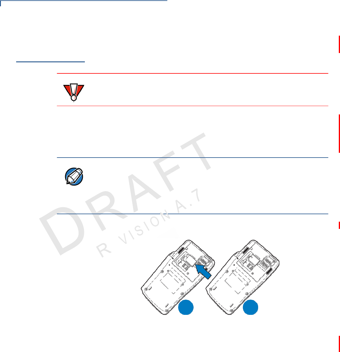
NOTE
Before inserting the MSAM card, position it as shown in Figure 5, with the card’s
gold contacts facing away from you, toward the unit. The cardholder slot in the
VX805 CTLS has a set of contacts. The MSAM card has a notch on one corner
to ensure that it fits into the connector base in only one way; the VX805 CTLS
has a matching notch cast into the backside of the MSAM compartment door to
ensure the MSAM card is positioned correctly when the cover is closed.
2 Install the MSAM card by aligning the card to match the embossed number
and carefully sliding it into the slots until fully inserted.
A
B
Figure 5 MSAM Insertion
3 Replace the compartment cover. See Opening and Replacing Card and
Connector
Compartment.
15
VX 805 CTLS INSTALLATION G
UIDE
S
ETUP
Cable Connections
Cable
Connections
There are various connections options for connecting the VX805 CTLS to power
and data sources using an appropriate cable.
Attaching a
Cable
Connector to
the
VX805 CTLS
External
Device
Connections
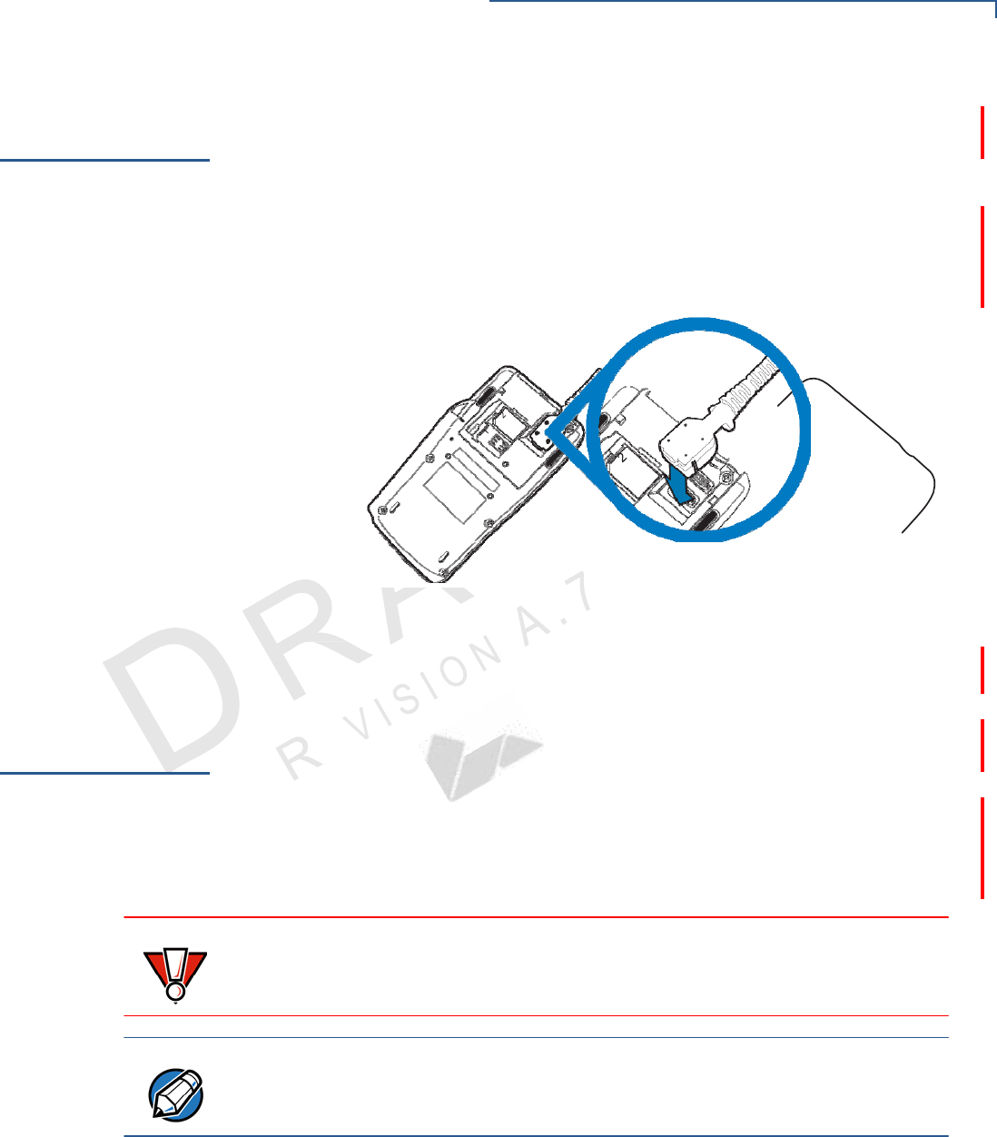
Before going into each cabling sceneario, attach the cable to the VX805 CTLS.
To attach a cable to the VX805 CTLS, see Opening and Replacing Card and
Connector Compartment to open the compartment door, then attach the 28-pin
connector of the cable to the VX805 CTLS, as shown in Figure 6.
Figure 6 Attaching a Cable Connector to the VX805 CTLS
After connecting the necessary cable, replace the compartment cover, as
described in Opening and Replacing Card and Connector Compartment.
The VX805 CTLS has four optional general cabling scenarios:
1 Connecting to Another VeriFone Terminal
2 Connecting to a Host Computer
3 Connecting to an Ethernet Port
4 Connecting to an ECR
CAUTION Using an incorrectly rated power supply can damage the unit or cause it not to
work properly. Use only a power pack with VPN PWR282-001-01-A (see
Specifications for detailed power supply specifications).
NOTE
For cabling options and ordering information, see Accessories and
Documentation.
16 VX 805 CTLS INSTALLATION G
UIDE
S
ETUP
External Device Connections
A
.
7
N
Connecting
to
Another
VeriFone
Terminal
Connect the VX805 CTLS to another VeriFone terminal using one of the following
connections:
• Connecting to Another VeriFone Terminal Directly Using a Coiled Cable
• Connecting to Another VeriFone Terminal Using a Junction Box
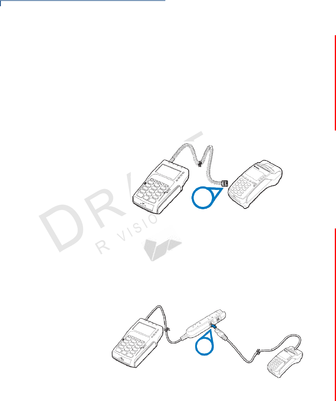
Connecting to Another VeriFone Terminal Directly Using a Coiled Cable
The VX805 CTLS directly connects to another VeriFone terminal using an RJ45
coiled cable (VPN - CBL282-030-xx-A) Connect the cable connector to the
VX805 CTLS (see Cable Connections) and connect to the VeriFone terminal
using the coiled cable. There is a minimum power requirement for the VX 805
CTLS, currently specified at 2.5W.
RS232
Figure 7 Connecting to Another VeriFone Terminal Directly Using a
Coiled
Cable
Connecting to Another VeriFone Terminal Using a Junction Box
The VX805 CTLS connects to another VeriFone terminal by using a junction box
(VPN CBL282-005-XX-A / CBL282-006-XX-A) and an RJ45–RJ45 coiled cable
(VPN 08356-XX-R). Connect the junction box to the VX805 CTLS using the
VX805 CTLS cable connector (see Cable Connections) and connect to the
VeriFone terminal using the RS232 cable.
RS232
Figure 8 Connecting to Another VeriFone Terminal Using a Junction
Box
17
VX 805 CTLS INSTALLATION G
UIDE
S
ETUP
External Device Connections
A
.
7
I
O
N
V
I
S
Connecting to a
Host Computer
Connect the VX805 CTLS to a host computer using one of the following
connections:
• Connecting to a Host Computer Using Direct USB Connection
• Connecting to a Host Computer Using a Junction Box
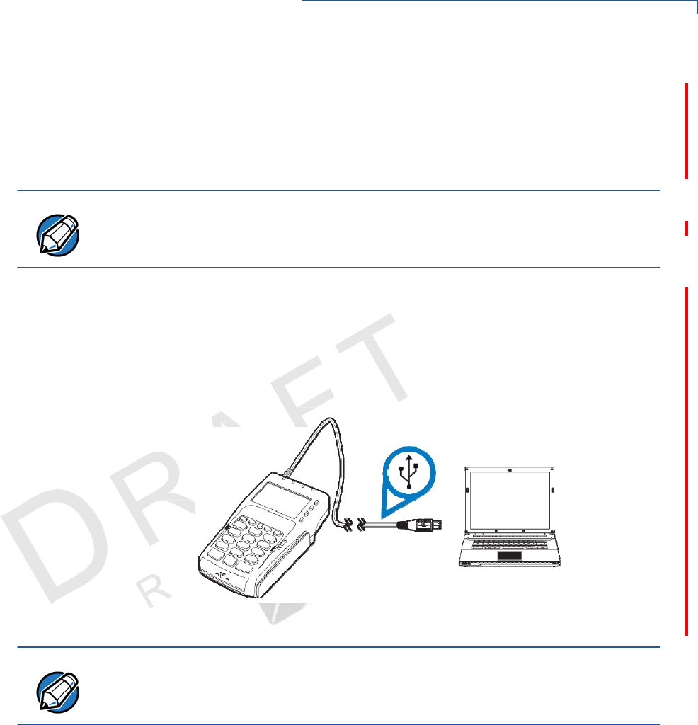
NOTE
You may use a PC or laptop as a host computer.
Connecting to a Host Computer Using Direct USB Connection
The USB Type-A connector (VPN - CBL282-025-xx-A) is required in standard
USB environments. For this cable option, the host end has a molded housing
which exposes the standard USB plug.
Connect the USB cable to the VX805 CTLS (see Cable Connections) and plug
the male USB connector into the corresponding USB host port on the computer.
Figure 9 Connecting to a Host Computer Using Direct USB Connection
NOTE
The VX805 CTLS can connect to a Self-Powered USB hub.
18 VX 805 CTLS INSTALLATION G
UIDE
S
ETUP
External Device Connections
VI
S
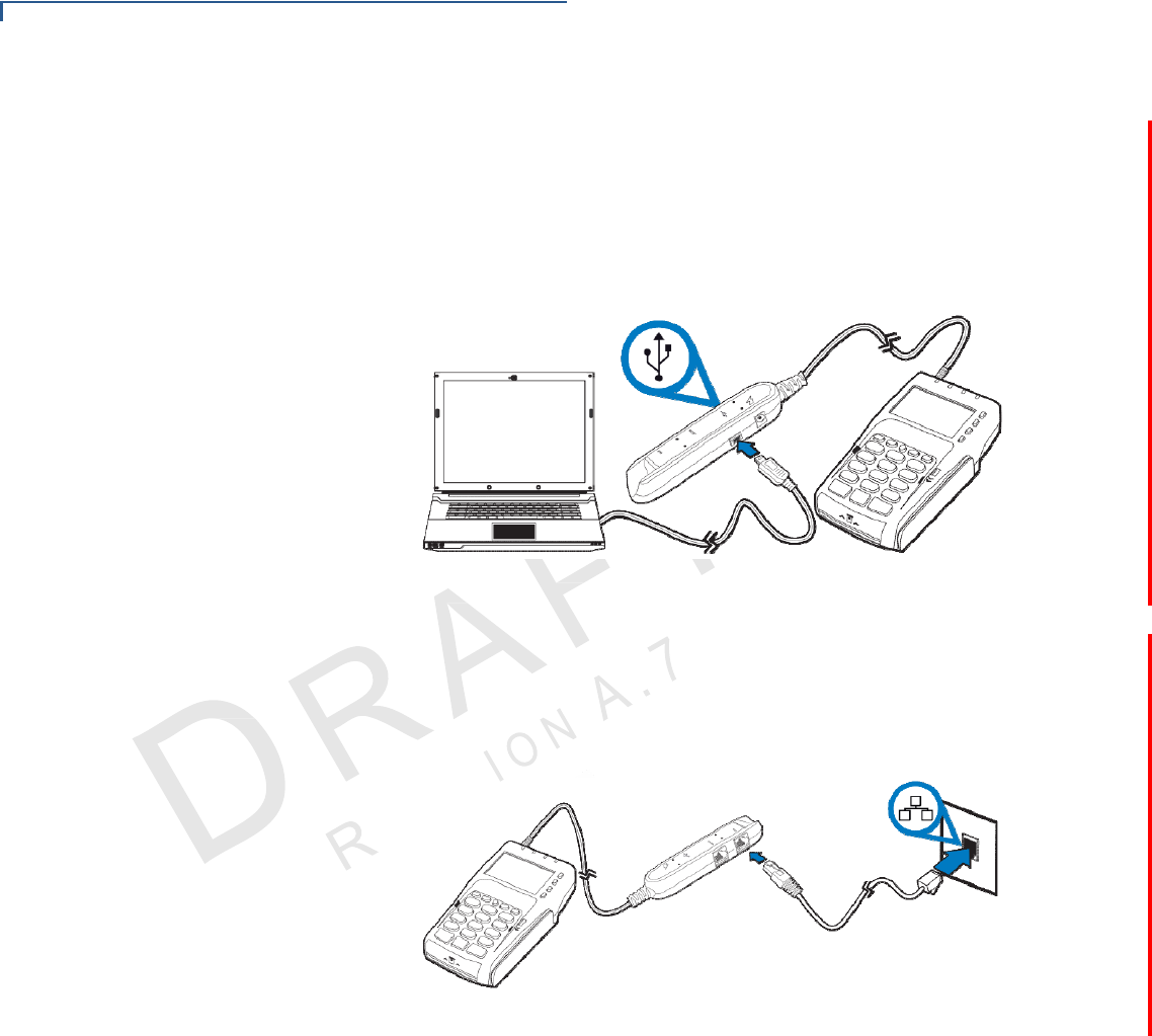
Connecting to a Host Computer Using a Junction Box
The VX805 CTLS connects to a host computer by using a junction box (VPN
CBL282-005-02-A). Connect the junction box to the VX805 CTLS using the
VX805 CTLS cable connector (see Cable Connections) and connect to the
computer using the USB connection on the junction box with a mini-USB cable
(VPN XXX).
Figure 10 Connecting to a Host Computer Using a Junction Box
Connecting to an
Ethernet Port
The VX805 CTLS connects to an Ethernet port by using a junction box (VPN
CBL282-005-02-A). Connect the junction box to the VX805 CTLS using
the
VX805 CTLS
cable connector (see Cable Connections). Using an RJ45 cable
(VPN XXX), connect the cable from the ETH port on the junction box to the
Ethernet port.
Figure 11 Connecting to an Ethernet Port
19
VX 805 CTLS INSTALLATION G
UIDE
S
ETUP
External Device Connections
Connecting to
an
ECR
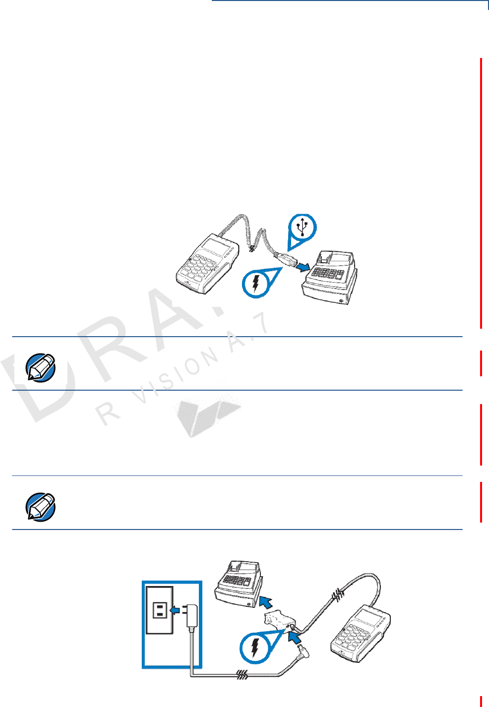
Connect the VX805 CTLS to an ECR using one of the following connections:
• Connecting to an ECR Using PoweredUSB
• Connecting to an ECR Using Serial Power Cable
Connecting to an ECR Using PoweredUSB
The VX805 CTLS connects to an ECR by using a direct PoweredUSB connector
(VPN - CBL282-033-xx-A). Connect the PoweredUSB cable to the VX805 CTLS
(see Cable Connections) and plug the male USB connector into
the corresponding
USB host port on the ECR.
Figure 12 Connecting to an ECR Using PoweredUSB
NOTE
In an ECR connection environment, the ECR would need to provide sufficent
power (2.5W) to the VX805 CTLS.
Connecting to an ECR Using Serial Power Cable
The VX805 CTLS connects to an ECR by using a serial power cable (VPN -
CBL282-031-xx-A). Connect the serial power cable to the VX805 CTLS (see
Cable Connections), then connect the DB-9 connector housing to the ECR.
NOTE When connecting an ECR by using a serial power cable, you need to also
connect the serial connection to an external power source. For further
instructions, see Connecting to External Power Using Serial Power Cable.
Figure 13 Connecting to an ECR Using Serial Power Cable
20 VX 805 CTLS INSTALLATION G
UIDE
S
ETUP
Power Supply
Power Supply
Not all VX805 CTLS configurations and device contexts require the use of
a power
supply – VeriFone ships power supplies with the VX805 CTLS as required.
If you have changed the context in which the VX805 CTLS is used or have
questions about which power supply should be used, contact your VeriFone
representative. For more information, see Accessories and Documentation.
CAUTION Using an incorrectly rated power supply can damage the unit or cause it not to
work properly. Use only a power pack with VPN PWR282-001-01-A (see
Specifications for detailed power supply specifications).
Before connecting a power supply, disconnect the power pack cord from the
power outlet.
Connect and route all cables between the VX805 CTLS and the ECR or PC
before plugging the power pack cord into a wall outlet or surge protector.
WARNING Do not plug the power pack into an outdoor outlet or operate the VX805 CTLS
outdoors. Also, disconnecting power during a transaction can cause transaction
data files not yet stored in memory to be lost.
NOTE
To protect against possible damage caused by lightning strikes and electrical
surges, VeriFone recommends installing a power surge protector.
When the VX805 CTLS has power and an application is loaded, the application
starts after the initial VeriFone copyright screen and displays a unique copyright
screen. If no application is loaded, DOWNLOAD NEEDED appears on the display
after the initial VeriFone copyright screen.
Power Connections For power connections, connect the VX805 CTLS to any of the following power
sources:
• Connecting to External Power Using Junction Box
• Connecting to External Power Using Serial Power Cable
CAUTION Using an incorrectly rated power supply can damage the unit or cause it not to
work properly. Use only a power pack with VPN PWR 282-001-01-A (see
Specifications for detailed power supply specifications and Accessories and
Documentation for ordering information).
21
VX 805 CTLS INSTALLATION G
UIDE
S
ETUP
Power Supply
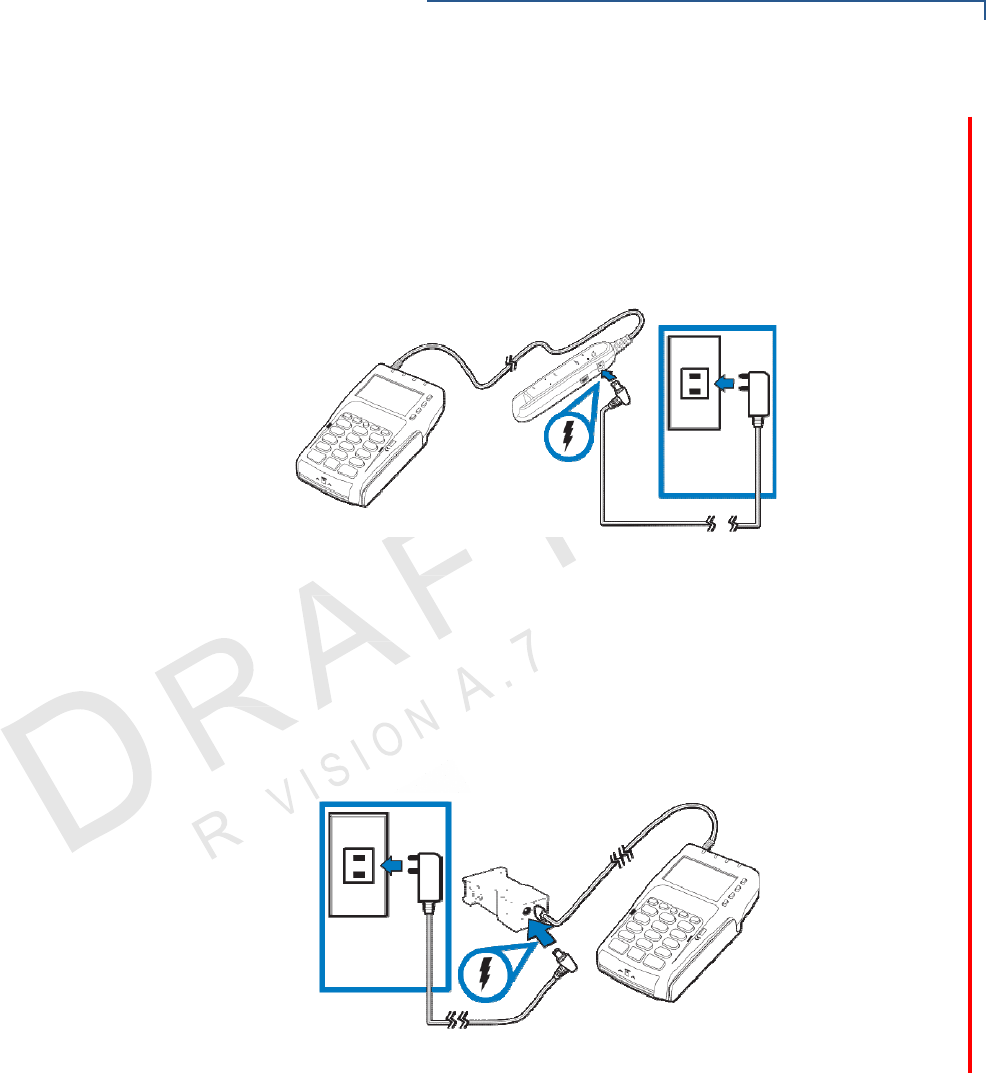
Connecting to External Power Using Junction Box
The VX805 CTLS connects to an external power source using a junction box
(VPN - CBL282-005-02-A / CBL282-006-XX-A). Connect the junction box to the
VX805 CTLS using the VX805 CTLS cable connector (see Cable Connections),
then connect the DC barrel into the junction box. Finally, plug the wall mount
adapter into a power outlet.
Figure 14 Connecting to External Power Using Junction Box
Connecting to External Power Using Serial Power Cable
The VX805 CTLS connects to an external power source by using a serial power
cable (VPN - CBL282-031-xx-A). Connect the serial power cable to the VX 805
CTLS using the VX805 CTLS cable connector (see Cable Connections), then
connect the DC barrel into the AC port in the serial power cable. Finally, plug the
wall mount adapter into a power outlet.
Figure 15 Connecting to External Power Using Serial Power Cable
22 VX 805 CTLS INSTALLATION G
UIDE
S
ETUP
USB Download Support
USB Download
Support
Use the USB direct connection for USB download support.
To perform
USB
download
Support
Using
the
Magnetic
Card
Reader
1 Connect the VX805 CTLS to the computer using a USB cable(see
Connecting to a Host Computer Using Direct USB
Connection).
2 Download the USB driver from the following location: http://verifone.com/
USBdriver.
Figure 16 USB Download Support
The VX805 CTLS has a magnetic card reader that uses a triple track stripe
reader. This gives the unit greater reliability over a wide range of swipe speeds
and operating environments.
To conduct a credit
or
debit card
transaction
Using the
Smart
Card Reader
1 Position a magnetic card with the stripe facing the keypad.
2 Swipe it through the magnetic card reader.
Figure 17 Using the Magnetic Card Reader
The smart card transaction procedure can vary depending on the application.
Verify the proper procedure with your application provider before performing a
smart card transaction.
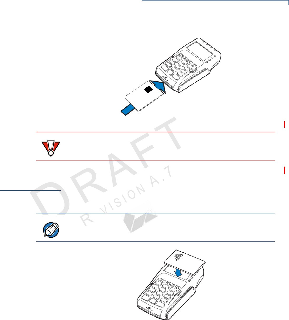
To conduct a smart
card transaction 1 Position the smart card with the gold contacts facing upward (see Figure 18).
2 Insert the card into the smart card reader slot in a smooth, continuous motion
until it seats firmly.
23
VX 805 CTLS INSTALLATION G
UIDE
S
ETUP
Using the Contactless Reader
3 Remove the card when the display indicates the transaction is completed.
Figure 18 Inserting a Smart Card
CAUTION
Using
the
Contactless
Reader
Leave the smart card in the card reader until the transaction is completed.
Premature removal can void the transaction.
The VX805 CTLS supports global contactless program specifications from
American Express, Discover, MasterCard, and Visa, with virtually no changes to
existing payment hardware or software.
1 The VX805 CTLS has four LEDs placed above the display and an audio
buzzer for contactless payment indications.
NOTE
The LED color options may vary depending on the region requirements.
For more
information, contact your local VeriFone representative or service provider.
Figure 19 Using the Contactless Reader

24 VX 805 CTLS INSTALLATION G
UIDE
S
ETUP
Optional Accessories
Optional
Accessories
These accessories can be used to further enhance the device’s functionality. See
Supplementary Hardware for additional information.
Using the
Privacy
Shield
The privacy shield is used to hide the keys a user is pressing to enter the
password for a transaction.
Installing the
Privacy
Shield
1 Align the hooks on the privacy shield with the corresponding slots beside the
keypad on the VX805 CTLS.
2 Once the hooks are in place, gently push down on the privacy shield until it
snaps into place.
The figure below shows an example of a VX805 CTLS with the privacy shield
installed.
Picture of VX 805 CTLS
Figure 20 Installed Privacy Shield

25
VX 805 CTLS INSTALLATION G
UIDE
CHAPTER 3
Specifications
This chapter discusses power requirements, dimensions, and other specifications
of the VX805 CTLS.
Unit Power
Requirements • Input voltage: 5V-12V DC
• USB Power, minimum 5 V, 500mA (without Ethernet)
Power Pack • PWR282-001-01-A (varies per region)
• UL, ITE listed, Class 2, switching power supply
• PS, 100-240V, 9V DC UNIVERSAL, 1A, 9W
Temperature • Operating temperature: 0° to 40° C (34° to 104° F)
• Storage temperature: -20° to 60° C (-4° to 140° F)
• Relative humidity: 5% to 90% RH non-condensing
External
Dimensions • Length : 158 mm (6.22 in.)
• Width: 83.1 mm (3.27 in.)
• Depth: 31.4 mm (1.24 in.)
Weight • Unit weight: 0.27 Kg (0.6 lbs.)
• Shipping weight: 0.45 Kg (1.0
lbs.)
Processor • 400 MHz ARM11 32-bit RISC processor
Memory • 160 MB (128 MB of Flash, 32 MB of mDDR)
Display • 128x64 FSTN
Magnetic
Card
Reader
• Triple track (tracks 1, 2, 3), high coercivity, bi-directional
Primary Smart Card • ISO 7816, 1.8V, 3V, 5V
• synchronous and asynchronous cards
• EMV Approved
SAM Card Reader • 2 Security Access Modules (SAMs)

26 VX 805 CTLS INSTALLATION G
UIDE
S
PECIFICATIONS
CTLS Card Reader • 4 LEDs for CTLS
Keypad • 3 x 5 secure numeric keypad
• 0-9 number keys
• *, #, Cancel, Backspace/Clear, and Enter keys
• Non-secure keypad matrix
• 4 Screen-addressable keys
• 4 ATM-style keys
• An “Alpha” key
Peripheral Ports • 1 USB Device port for connecting directly to another USB host port (ie. ECR or
payment terminal).
• 1 Ethernet port for connecting to Ethernet LAN network.
• 1 RS-232 Serial port.
• 2 14-pin input/output connector for backward compatibility.
Security • 3DES encryption, Master/Session and DUKPT key management
• VeriShield file authentication
• PCI PED 3.0 approved

27
VX 805 CTLS INSTALLATION G
UIDE
CHAPTER 4
Maintenance and Cleaning
Your VX805 CTLS device is a product of superior design and craftsmanship and
should be treated with care. It has no user-serviceable parts. The following
suggestions will help you protect your warranty coverage.
• Keep the device dry. Precipitation, humidity, and all types of liquids or
moisture can contain minerals that will corrode electronic circuits. If your
device does get wet, switch off the power, and allow the device to dry
completely before replacing it.
• Do not use or store the device in dusty, dirty areas. Its moving parts and
electronic components can be damaged.
• Do not store the device in hot areas. High temperatures can shorten the
life of electronic devices, damage batteries, and warp or melt certain
plastics.
• Do not store the device in cold areas. When the device returns to its
normal temperature, moisture can form inside the device and damage
electronic circuit boards.
• Do not drop, knock, or shake the device. Rough handling can break
internal circuit boards and fine mechanics.
• Do not use harsh chemicals, cleaning solvents, or strong detergents to
clean the device. Use only a soft, clean, dry cloth for cleaning.
• Do not paint the device. Paint can clog the moving parts and prevent
proper operation.
• Keep the device free from any small, loose items (such as paper clips,
staples, or coins) that could accidentally get inside it through an opening,
such as the SD card reader slot or the primary smart card reader slot.
• Do not attempt to open the device other than as instructed in this guide.
This device has security features that protect it from tampering. For
example, if the device’s outer casing is opened, file content will be deleted.
28 VX 805 CTLS INSTALLATION G
UIDE
MAINTENANCE AND C
LEANING
Additional Safety Information
These suggestions apply equally to your VX805 CTLS device, or any of its
attachments or accessories. If your device is not working properly, take it to the
nearest authorized service facility for servicing or replacement. For your safety,
have this device serviced only by a VeriFone-authorized service provider.
CAUTION Never use thinner, trichloroethylene, or ketone-based solvents – they can
deteriorate plastic or rubber parts.
Do not spray cleaners or other solutions directly onto the keypad or display.
Additional
Safety
Information
The following are additional information for your safety in using this device.
Power Adapter Use only the power adapter that came with your device. Adapters for other
electronic devices may look similar, but they may affect your device’s performance
or damage it.
Potentially
Explosive
Environments
Do not use this device in any area with a potentially explosive atmosphere, and
obey all signs and instructions. Potentially explosive atmospheres include areas
where you would normally be advised to turn off your vehicle engine. Sparks in
such areas could cause an explosion or fire resulting in bodily injury or even
death.
Card Readers Do not attempt to clean the card readers. Doing so can void any warranty. For
card reader service, contact your VeriFone distributor or service provider.

CHAPTER 5
29
VX 805 CTLS INSTALLATION G
UIDE
Service and Support
For VX805 CTLS problems, contact your local VeriFone representative or service
provider.
For VX805 CTLS product service and repair information:
• USA – VeriFone Service and Support Group, 1-800-834-4366,
Monday - Friday, 8 A.M. - 8 P.M., eastern time.
• International – Contact your VeriFone representative.
Service Returns Before returning the VX805 CTLS to VeriFone, you must obtain a Merchandise
Return Authorization (MRA) number. The following procedure describes how to
return one or more VX805 CTLS for repair or replacement (U.S. customers only).
NOTE
International customers, please contact your local VeriFone representative for
assistance with your service, return, or replacement.
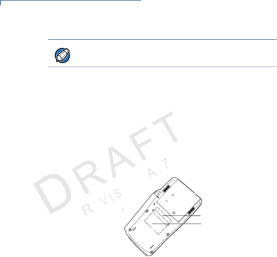
1 Gather the following information from the printed labels (see Figure 21) on the
bottom of each VX805 CTLS to be returned:
• Product ID, including the model and part number. For example,
“m280-xxx-xx” and “PTID xxxxxxxx.”
• Serial number (S/N xxx-xxx-xxx).
2 Within the United States, call VeriFone toll-free at 1-800-834-4366.
3 Select the MRA option from the automated message. The MRA department is
open Monday–Friday, 8 A.M.–8 P.M., eastern time.
4 Give the MRA representative the information gathered in Step 1.
If the list of serial numbers is long, you can fax the list, along with the
information gathered in Step 1, to the MRA department at 1-727-953-4172
(U.S.).
• Please address the fax clearly to the attention of the “VeriFone MRA
Dept.”
• Include a telephone number where you can be reached and your fax
number.
SERVICE AND S
UPPORT
Service Returns
30 VX 805 CTLS INSTALLATION G
UIDE
IO
N
• You will be issued MRA number(s) and the fax will be returned to you.
NOTE
One MRA number must be issued for each VX805 CTLS you return to VeriFone,
even if you are returning several of the same model.
5 Describe the problem(s) and provide the shipping address where the repaired
or replacement unit must be returned.
6 Keep a record of the following items:
• Assigned MRA number(s).
• VeriFone serial number assigned to the VX805 CTLS you are returning for
service or repair (serial numbers are located on the bottom of the unit (see
Figure 21).
• Shipping documentation, such as air bill numbers used to trace the
shipment.
• Model(s) returned (model numbers are located on the VeriFone label on
the bottom of the VX805 CTLS).
MODEL
NUMBER
SERIAL
NUMBER
Figure 21 Information Labels on Unit Bottom

31
VX 805 CTLS INSTALLATION G
UIDE
SERVICE AND S
UPPORT
Accessories and Documentation
Accessories
and
Documentation
VeriFone produces accessories and documentation for the VX805 CTLS. When
ordering, please refer to the part number in the left column.
VeriFone Online Store at www.store.verifone.com
• USA – VeriFone Customer Development Center, 1-800-834-4366,
Monday - Friday, 7 A.M. - 8 P.M., eastern time
• International – Contact your VeriFone representative
Supplementary
Hardware
The following part(s) come as optional accessories:
PPL280-032-01-A Privacy shield
Data Cables The following cables can be used with the VX805 CTLS:
CBL282-030-xx-A VX805 CTLS–RJ45 coiled cable. Connects to
other VX805 CTLS devices and other
countertop terminals.
CBL282-025-xx-A VX805 CTLS–USB cable. Connects the
VX805 CTLS to an ECR or other USB devices
that support USB Type A.
CBL282-031-xx-A VX805 CTLS–DB9 serial power cable.
Connects the VX805 CTLS to other generic
RS232 supported devices.
CBL282-005-xx-A VX805 CTLS–Junction Box. Ethernet, mini-
USB and serial version.
CBL282-006-xx-A VX805 CTLS–Junction Box. Ethernet with
serial connection.
08356-XX-R RJ45–RJ45 coiled cable. RS232 connection.
VPN mini-USB–Type A connection cable.
VPN Ethernet cable.
Various others, depending on what they connect to. Contact your local
VeriFone representative or service provider to identify the best cable for your
needs.
Power Supply The VX805 CTLS package includes any of the following types of power
packs:
PWR282-001-01-A DC power pack (US)
PWR282-002-01-A DC power pack (UK)
PWR282-003-01-A DC power pack (EU)

32 VX 805 CTLS INSTALLATION G
UIDE
SERVICE AND S
UPPORT
Accessories and Documentation
33
VX 805 CTLS INSTALLATION G
UIDE
CHAPTER 6
Troubleshooting
Guidelines
This chapter lists typical examples of malfunctions that you may encounter while
operating your VX805 CTLS and the steps that you can take to resolve them.
The troubleshooting guidelines provided in the following section are included to
assist successful installation and configuration of the VX805 CTLS. If you are
having problems operating your VX805 CTLS, please read these troubleshooting
examples. If the problem persists even after performing the outlined guidelines or
if the problem is not described, contact your local VeriFone representative for
assistance.
NOTE The VX805 CTLS comes equipped with tamper-evident labels. The VX 805
CTLS contains no user-serviceable parts. Do not, under any circumstance,
attempt to disassemble the unit. Perform only those adjustments or repairs
specified in this guide. For all other services, contact your local VeriFone service
provider. Service conducted by parties other than authorized VeriFone
representatives may void any warranty.
CAUTION Not all units require use of a power supply.
Using an incorrectly rated power supply may damage the unit or cause it not to
work properly. Before troubleshooting, ensure that the power supply used to
power the unit matches the requirements specified on the back of the unit (see
Specifications for detailed power supply specifications). If not, obtain the
appropriately rated power supply before continuing with troubleshooting.
PIN Pad Does
Not Start
When the PIN pad does not start up:
• Check power connections.
• Connect the VX805 CTLS into a known-good power supply.
• If the problem persists, contact your local VeriFone representative for
assistance.
Blank Display When the VX805 CTLS display does not show correct or clearly readable
information:
• Check all power and cable connections.
• Remove and reapply power to the unit.
• Connect the VX805 CTLSnto a known-good power supply.
• If the problem persists, contact your local VeriFone service provider.

TROUBLESHOOTING G
UIDELINES
Keypad Does Not Respond
34 VX 805 CTLS INSTALLATION G
UIDE
Keypad Does
Not Respond
Transactions
Fail To Process
If the keypad does not respond properly:
• Check the display. If it displays the wrong character or nothing at all when you
press a key, follow the steps outlined in Transactions Fail To Process.
• If pressing a function key does not perform the expected action, refer to the
user documentation for that application to ensure you are entering data
correctly.
• If the problem persists, contact your local VeriFone representative.
There are several possible reasons why the unit may not be processing
transactions. Use the following steps to troubleshoot failures.
Check Magnetic Card Reader
• Perform a test transaction using one or more different magnetic stripe cards to
ensure the problem is not a defective card.
• Ensure that you are swiping cards properly (see Using the Magnetic Card
Reader).
• Process a transaction manually using the keypad instead of the card reader. If
the manual transaction works, the problem may be a defective card reader.
• If the problem persists, contact your local VeriFone representative.
Check Smart Card Reader
• Perform a test transaction using several different smart cards to ensure the
problem is not a defective card.
• Ensure that the card is inserted correctly (see Using the Smart Card Reader).
• Ensure the MSAM cards are properly inserted in the slots and are properly
secured (see Installing and Replacing MSAM Cards).
• If the problem persists, contact your local VeriFone representative.
Check Contactless Reader
• Perform a test transaction using one or more different contactless cards to
ensure the problem is not a defective card.
• Ensure that you are conducting the contactless transaction properly (see
Using the Contactless Reader).
• If the problem persists, contact your local VeriFone representative.

35
VX 805 CTLS INSTALLATION G
UIDE
TROUBLESHOOTING G
UIDELINES
Transactions Fail To Process

VeriFone, Inc.
2099 Gateway Place, Suite 600
San Jose, CA, 95110 USA
Tel: (800) VeriFone (837-4366)
www.verifone.com
VX805 CTLS
Installation Guide
VeriFone Part Number DOC280-023-EN-A, Revision A.7