Verifone E265 Point of Sale Terminal User Manual e265 Installation Guide
VeriFone Inc Point of Sale Terminal e265 Installation Guide
Verifone >
Contents
- 1. User Manual
- 2. Users Manual Statement
- 3. Users Manual
User Manual
Verifone Part Number DOC087-303-EN-A, Revision A.2
VERIFONE
CONFIDENTIAL
REVISION A.2
e265
Installation Guide

All rights reserved. No part of the contents of this document may be reproduced or transmitted in any form without the written
permission of Verifone, Inc.
The information contained in this document is subject to change without notice. Although Verifone has attempted to ensure the
accuracy of the contents of this document, this document may include errors or omissions. The examples and sample programs are
for illustration only and may not be suited for your purpose. You should verify the applicability of any example or sample program
before placing the software into productive use. This document, including without limitation the examples and software programs, is
supplied “As-Is.”
Verifone, Inc.
1-800-Verifone
www.verifone.com
Verifone Part Number DOC087-303-EN-A, Revision A.2
e265 Installation Guide
© 2015 Verifone, Inc.
VERIFONE
CONFIDENTIAL
REVISION A.2
Verifone and the Verifone logo are registered trademarks of Verifone. Other brand names or trademarks associated with Verifone’s
products and services are trademarks of Verifone, Inc.
All other brand names and trademarks appearing in this manual are the property of their respective holders.
Comments? Please e-mail all comments on this document to your local Verifone Support Team.
WARNING
The e355 uses a lithium-ion rechargeable battery. Do not dispose the e355 in a fire.
Lithium-ion polymer batteries must be recycled or disposed of properly. Do not
dispose lithium-ion polymer batteries in municipal waste sites.

E265 INSTALLATION GUIDE 3
VERIFONE
CONFIDENTIAL
REVISION A.6
CONTENTS
PREFACE . . . . . . . . . . . . . . . . . . . . . . . . . . . . . . . . . . . . . . . 5
Audience. . . . . . . . . . . . . . . . . . . . . . . . . . . . . . . . . . . . . . . . . . . . . . . . . . . . . . . . 5
Organization . . . . . . . . . . . . . . . . . . . . . . . . . . . . . . . . . . . . . . . . . . . . . . . . . . . . . 5
Related Documentation . . . . . . . . . . . . . . . . . . . . . . . . . . . . . . . . . . . . . . . . . . . . 5
Conventions and Acronyms . . . . . . . . . . . . . . . . . . . . . . . . . . . . . . . . . . . . . . . . . 6
CHAPTER 1
Device Overview Features and Benefits . . . . . . . . . . . . . . . . . . . . . . . . . . . . . . . . . . . . . . . . . . . . . 8
Exceptional Ease of Use. . . . . . . . . . . . . . . . . . . . . . . . . . . . . . . . . . . . . . . . . 8
Performance and Durability . . . . . . . . . . . . . . . . . . . . . . . . . . . . . . . . . . . . . . 8
Security. . . . . . . . . . . . . . . . . . . . . . . . . . . . . . . . . . . . . . . . . . . . . . . . . . . . . . 8
Contactless Capability . . . . . . . . . . . . . . . . . . . . . . . . . . . . . . . . . . . . . . . . . . 8
CHAPTER 2
Device Setup Usage Guidelines . . . . . . . . . . . . . . . . . . . . . . . . . . . . . . . . . . . . . . . . . . . . . . . . 10
Environmental Factors . . . . . . . . . . . . . . . . . . . . . . . . . . . . . . . . . . . . . . . . . 10
Personal Security Considerations. . . . . . . . . . . . . . . . . . . . . . . . . . . . . . . . . 10
Electrical Considerations . . . . . . . . . . . . . . . . . . . . . . . . . . . . . . . . . . . . . . . 10
Unpacking the Shipping Carton . . . . . . . . . . . . . . . . . . . . . . . . . . . . . . . . . . . . . 10
Examining e265 Device Features. . . . . . . . . . . . . . . . . . . . . . . . . . . . . . . . . . . . 11
Front View. . . . . . . . . . . . . . . . . . . . . . . . . . . . . . . . . . . . . . . . . . . . . . . . . . . 11
Back View . . . . . . . . . . . . . . . . . . . . . . . . . . . . . . . . . . . . . . . . . . . . . . . . . . . 12
Installing/Replacing an MSAM Card . . . . . . . . . . . . . . . . . . . . . . . . . . . . . . . 13
Manually Starting and Resetting the e265 . . . . . . . . . . . . . . . . . . . . . . . . . . 14
Connecting the e265 to a Power Source or a Host Computer . . . . . . . . . . . 15
Color Behavior . . . . . . . . . . . . . . . . . . . . . . . . . . . . . . . . . . . . . . . . . . . . . . . 16
Using the Smart Card Reader. . . . . . . . . . . . . . . . . . . . . . . . . . . . . . . . . . . . 17
Using the Magnetic Stripe Reader . . . . . . . . . . . . . . . . . . . . . . . . . . . . . . . . 17
Using the CTLS Reader . . . . . . . . . . . . . . . . . . . . . . . . . . . . . . . . . . . . . . . . 18
CHAPTER 3
Specifications Power . . . . . . . . . . . . . . . . . . . . . . . . . . . . . . . . . . . . . . . . . . . . . . . . . . . . . . . . . 19
Temperature. . . . . . . . . . . . . . . . . . . . . . . . . . . . . . . . . . . . . . . . . . . . . . . . . . . . 19
External Dimensions. . . . . . . . . . . . . . . . . . . . . . . . . . . . . . . . . . . . . . . . . . . . . . 19
CHAPTER 4
Maintenance Cleaning the Device . . . . . . . . . . . . . . . . . . . . . . . . . . . . . . . . . . . . . . . . . . . . . . 21
Smart Card Reader . . . . . . . . . . . . . . . . . . . . . . . . . . . . . . . . . . . . . . . . . . . . . . 21
CHAPTER 5
Verifone Service
and Support Returning a Device for Service. . . . . . . . . . . . . . . . . . . . . . . . . . . . . . . . . . . . . . 23
Accessories and Documentation . . . . . . . . . . . . . . . . . . . . . . . . . . . . . . . . . . . . 24
Accessories. . . . . . . . . . . . . . . . . . . . . . . . . . . . . . . . . . . . . . . . . . . . . . . . . . 24
Documentation . . . . . . . . . . . . . . . . . . . . . . . . . . . . . . . . . . . . . . . . . . . . . . . 24
Battery Pack Instructions . . . . . . . . . . . . . . . . . . . . . . . . . . . . . . . . . . . . . . . . . . 24

CONTENTS
4E265 INSTALLATION GUIDE
VERIFONE
CONFIDENTIAL
REVISION A.6
CHAPTER 6
Troubleshooting
Guidelines Device Does Not Start . . . . . . . . . . . . . . . . . . . . . . . . . . . . . . . . . . . . . . . . . . . . 25
Device Display Does Not Show Correct/Readable Info . . . . . . . . . . . . . . . . . . . 25
Blank Display . . . . . . . . . . . . . . . . . . . . . . . . . . . . . . . . . . . . . . . . . . . . . . . . . . . 26
Keypad Does Not Respond . . . . . . . . . . . . . . . . . . . . . . . . . . . . . . . . . . . . . . . . 26
Transactions Fail To Process. . . . . . . . . . . . . . . . . . . . . . . . . . . . . . . . . . . . . . . 26

E265 INSTALLATION GUIDE 5
VERIFONE
CONFIDENTIAL
REVISION A.6
PREFACE
This guide is your primary source of information for setting up the e265.
Audience
This guide is useful for anyone installing an e265 device. Basic descriptions of the
device features are also provided.
Organization
This guide is organized as follows:
Chapter 1, Device Overview. Provides an overview of the e265.
Chapter 2, Device Setup. Explains how to set up the e265 device. It tells you how
to select a location, establish power connection, and install the MSAM card.
Chapter 3, Specifications. Discusses power requirements and dimensions of the
e265.
Chapter 4, Maintenance. Explains how to maintain your e265.
Chapter 5, Verifone Service and Support. Provides information on how to contact
your local Verifone representative or service provider, and information on how to
order accessories or documentation from Verifone.
Chapter 6, Troubleshooting Guidelines. Provides troubleshooting guidelines,
should you encounter a problem in device installation.
Related
Documentation
To learn more about the e265, refer to the following set of documents:
e265 Certifications and Regulations Sheet VPN DOC087-301-EN
e265 Quick Installation Guide VPN DOC087-302-EN
e265 Web site www.paywaremobile.com
PREFACE
Conventions and Acronyms
6E265 INSTALLATION GUIDE
VERIFONE
CONFIDENTIAL
REVISION A.6
Conventions and
Acronyms
This section describes the conventions and acronyms used in this guide.
Various conventions are used to help you quickly identify special formatting.
Table 1 describes these conventions and provides examples of their use.
Various acronyms are used in place of the full definition. Table 2 presents
acronyms and their definitions.
Table 1 Document Conventions
Convention Meaning Example
Blue Text in blue indicates terms that
are cross referenced.
See Conventions and Acronyms.
Italics Italic typeface indicates book
titles or emphasis.
You must install a roll of thermal-
sensitive paper in the printer.
Courier The courier type face is used
while specifying onscreen text,
such as text that you would
enter at a command prompt, or
to provide an URL.
http://www.verifone.com
The pencil icon is used to
highlight important information.
RS-232-type devices do not work
with the PIN pad port.
The caution symbol indicates
possible hardware or software
failure, or loss of data.
The device is not waterproof or
dustproof, and is intended for
indoor use only.
The lightning symbol is used as
a warning when bodily injury
might occur.
Due to risk of shock do not use the
device near water.
Table 2 Acronym Definitions
Acronym Definitions
AC Alternating Current
ARM Acorn RISC Machine
EMV Europay MasterCard and VISA
LCD Liquid Crystal Display
LED Light Emitting Diode
NFC Near Field Communication
MRA Merchandise Return Authorization
MSAM Micromodule-Size Security Access Module
PCI Payment Card Industry
PED PIN Entry Device
PIN Personal Identification Number
SIM Subscriber Identity Module
USB Universal Serial Bus
VPN Verifone Part Number
NOTE
CAUTION
WARNING
E265 INSTALLATION GUIDE 7
VERIFONE
CONFIDENTIAL
REVISION A.6
CHAPTER 1
Device Overview
This chapter provides a brief description of the e265.
The e265 connects with various tablet devices for the next generation of PAYware
Mobile enterprise. It supports the use of the SPP standard to connect between the
e265 and tablet.
Some of the e265’s key features include: a fast processor, large memory, the
latest PCI 4.0 security, mechanical keypad, integrated contactless and NFC-
ready, in a small most versatile form factor.
The e265 is a portable, battery-powered device designed to fit your hands
comfortably and is ideal for consumer-facing and merchant-facing retail integrated
applications. It has a removable battery that can be charged by external power
adapter through a micro-USB connector and gang charger. It also features a crisp
128 x 32 backlit LCD display.
Figure 1 The e265 Unit
Key Features
•400 MHz ARM11 processor delivers
power and usability in a convenient
“hand-over” design
•Offers unsurpassed performance on
EMV smart card transactions
•Multi-application operating
environment
•Security architecture exceeds
specifications for PCI-PED and
sophisticated file authentication
•Advanced memory architecture to
meet tomorrow’s needs
•Multiple connectivity and
contactless options
•32-bit processing and multi-tasking
capabilities
•Spill-resistant design prevents liquid
from entering the unit by forcing it down
and off the front of the device

DEVICE OVERVIEW
Features and Benefits
8E265 INSTALLATION GUIDE
VERIFONE
CONFIDENTIAL
REVISION A.6
Features and
Benefits
The e265 provides the right combination of features and functions including a
triple-track magnetic-stripe card reader, smart card reader, integrated PIN pad,
colored display, and contactless/NFC support.
Exceptional Ease of
Use
•The lightweight, compact, stylish, and ergonomic balance allows convenient
device hand-off to the consumer for PIN entry or other input.
•Large, well-placed, mechanical keys provide a continuity of user experience
between the e265 and the iOS, Android, or Windows device.
•Horizontal magnetic stripe card reader with an enlarged card entrance delivers
optimal card swiping and reading without the need to visually guide the card.
•The e265 size is easily able to be dropped in most pockets. An optional
hands-free holster is available that fits the server’s or clerk’s belt so that the
e265 can be quickly removed and easily handed to the customer.
Performance and
Durability
•Powerful 400-mHz ARM11 processing completes transactions quickly.
•High-capacity lithium-ion polymer battery can rapidly charge and offer 10+
hours of power.
•Standard Micro-USB port allows for convenient product charging.
•Rounded corners to minimize breakage and drop-resistant to 3 feet on
concrete surfaces.
•192 MB of standard memory.
Security
•PCI PED 4.x approved for debit and other PIN-based transactions
•EMV Level 1 type approval
•Tamper-resistant construction, SSL protocols, and VeriShield file
authentication
•Supports VeriShield Protect encryption implementations
Contactless
Capability
•Advanced contactless architecture that future-proofs investment with a single
contactless interface (SingleCl), SoftSAMs, and side-by-side application
architecture.
•Large tap zone (above the keypad) that encompasses the PIN pad optimizes
user experience.
•Contactless version accepts EMV in addition to magnetic stripe contactless
payments as well as PIN-based transactions.

E265 INSTALLATION GUIDE 9
VERIFONE
CONFIDENTIAL
REVISION A.6
CHAPTER 2
Device Setup
This chapter describes the device setup procedure. You will learn about:
•Usage Guidelines
•Unpacking the Shipping Carton
•Examining e265 Device Features
•Installing/Replacing an MSAM Card
•Manually Starting and Resetting the e265
•Connecting the e265 to a Power Source or a Host Computer
•Color Behavior
•Using the Smart Card Reader
•Using the Magnetic Stripe Reader
•Using the CTLS Reader

DEVICE SETUP
Usage Guidelines
10 E265 INSTALLATION GUIDE
VERIFONE
CONFIDENTIAL
REVISION A.6
Usage
Guidelines
Use the following guidelines when using your e265.
Environmental
Factors
•Select a flat support surface, such as a countertop or table, to keep the device
safe in between uses.
•Do not use the device where there is high heat, dust, humidity, moisture, or
caustic chemicals or oils.
•Keep the device away from direct sunlight and anything that radiates heat,
such as a stove or motor.
•Do not use the device outdoors.
Personal Security
Considerations
The e265 is a handover device. Always exercise extreme caution when
conducting transactions especially during PIN entry.
•Hand the e265 directly to the cardholder for PIN entry.
•Encourage the cardholder to hold the e265 close to avoid others from seeing
the information entered.
Electrical
Considerations
•Avoid using this product during electrical storms.
•Avoid locations near electrical appliances or other devices that cause
excessive voltage fluctuations or emit electrical noise (for example, air
conditioners, electric motors, neon signs, high-frequency or magnetic security
devices, or computer equipment).
•Do not use the device near water or in moist conditions.
Unpacking the
Shipping Carton
Open the shipping carton and carefully inspect its contents for possible tampering
or shipping damage. The e265 is a secure product and any tampering may cause
the device to cease to function properly.
To unpack the
shipping carton 1Remove and inspect the following items:
•e265 unit
•USB to Micro-USB cable
2Remove all plastic wrapping from the unit and other components.
CAUTION
The device is not waterproof or dustproof, and is intended for indoor use only.
Any damage to the unit from exposure to rain or dust may void any warranty.
DEVICE SETUP
Examining e265 Device Features
E265 INSTALLATION GUIDE 11
VERIFONE
CONFIDENTIAL
REVISION A.6
3Remove the clear protective film from the unit.
4Save the shipping carton and packing material for future repacking or moving
the device.
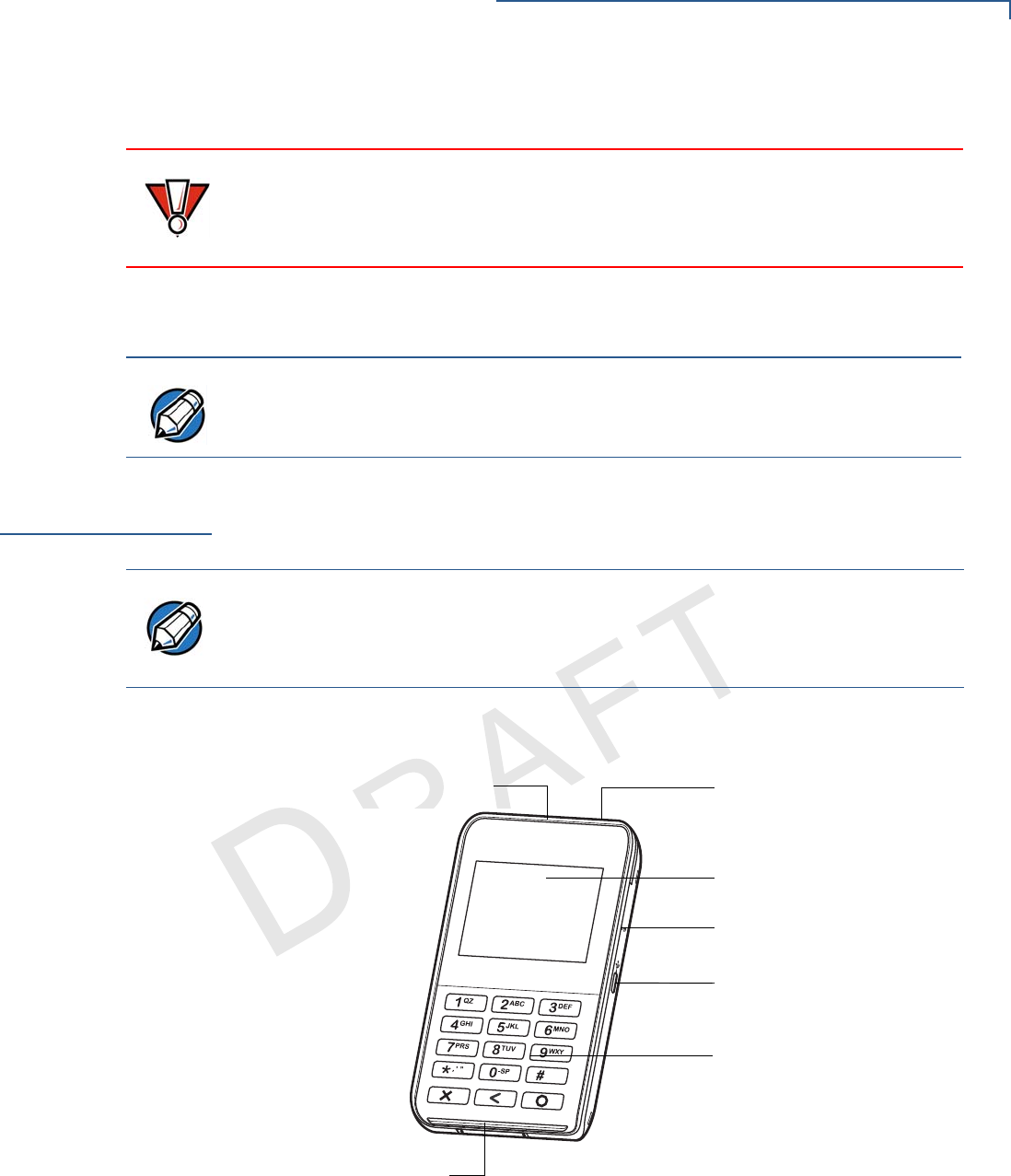
Examining e265
Device Features
Before you continue the installation process, familiarize yourself with the features
of the e265. (See Figure 3 and Figure 2)
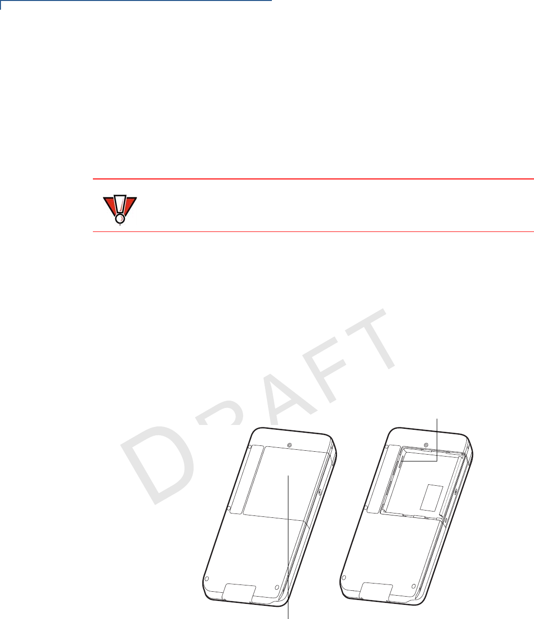
Front View
The front panel includes the following features:
Figure 2 e265 Device Features (Front View)
•A 128 x 32 pixel backlit LCD Display
•A Power LED Indicator beside the Micro-USB port indicates the e265
device’s operational state.
CAUTION
Do not use a unit that has been damaged or tampered with. The e265 comes
equipped with tamper-evident labels. If a label or component appears damaged
or if the device appears to have been opened, please notify the shipping
company and your Verifone representative or service provider immediately.
NOTE
Charge the e265 device for eight hours before initial use.
NOTE
Verifone ships variants of the e265 for different markets. Your device may have a
different configuration. The following devices may or may not be present: a CTLS
reader or smart card reader. However, the basic processes described in this guide
remain the same, regardless of device configuration.
LCD DISPLAY
KEYPAD
2D IMAGER
POWER LED INDICATOR
MICRO-USB PORT
MAGNETIC STRIPE READER
SMART CARD READER
DEVICE SETUP
Examining e265 Device Features
12 E265 INSTALLATION GUIDE
VERIFONE
CONFIDENTIAL
REVISION A.6
•A Micro-USB port located on the right side for data connection and power
charging. You can also use this connect the e265 to a computer using a
standard USB to Micro-USB cable (VPN CBL000-049-01-A). (See Connecting
the e265 to a Power Source or a Host Computer)
•Two types of keys on the mechanical keypad:
aA 12-key keypad
bThree color-coded function keys below the keypad
•A Smart Card Reader to process smart card transactions (See Using the
Smart Card Reader)
•A Magnetic Stripe Reader, for performing debit or credit card transactions
(See Using the Magnetic Stripe Reader).
•LEDs that act as CTLS activity, system power, and charging indicators (See
Color Behavior)
•A CTLS functionality for contactless payments (See Using the CTLS
Reader)
Back View
The front panel includes the following features:
Figure 3 e265 Device Features (Back View)
•A Battery Compartment Cover. Remove the cover to access the removable
battery and the MSAM compartment.
CAUTION
Do NOT paste anything on the keypad surface to avoid malfunction.
BATTERY COMPARTMENT COVER
MSAM COMPARTMENT
DEVICE SETUP
Examining e265 Device Features
E265 INSTALLATION GUIDE 13
VERIFONE
CONFIDENTIAL
REVISION A.6
•An MSAM (Micromodule-Size Security Access Module) Compartment to
support stored-value card programs or other merchant card requirements.
(See Installing/Replacing an MSAM Card)
Installing/Replacing
an MSAM Card
When you first receive your e265, you may need to install an MSAM card or you
may need to replace an old card.
To install/replace
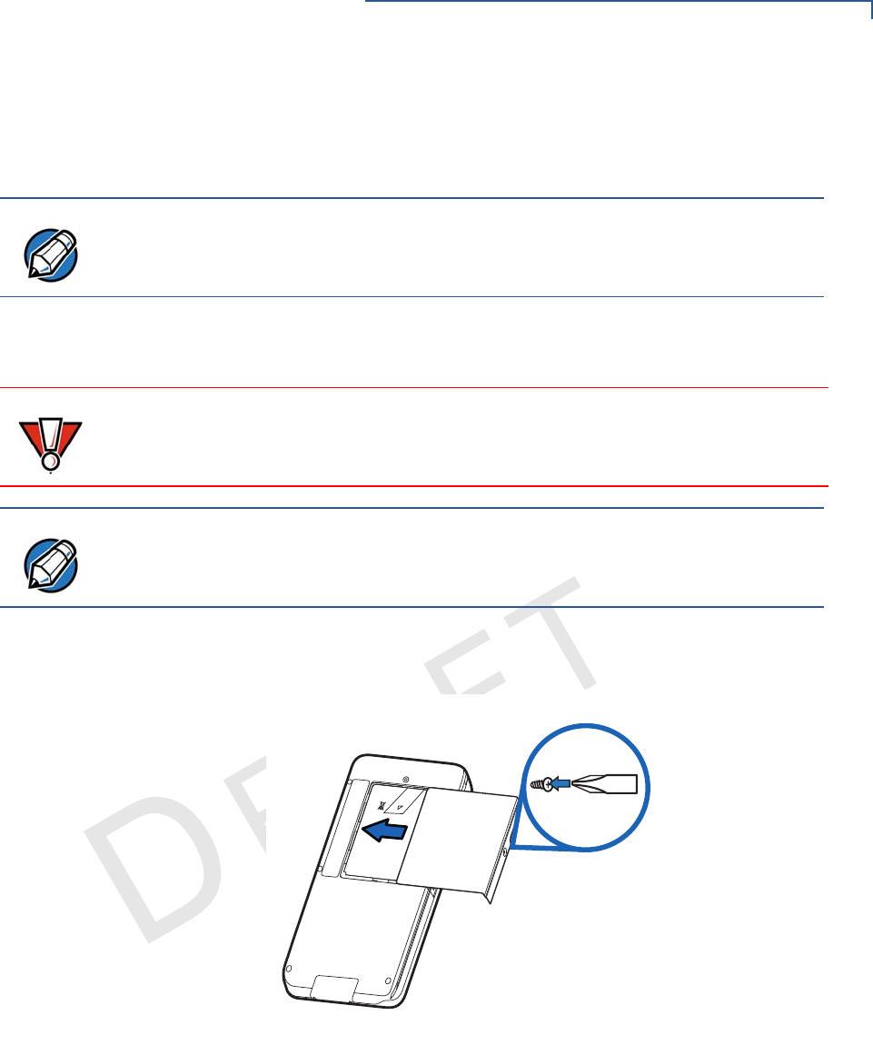
MSAM 1Unplug any cables or chargers from the e265.
2Remove the screw from the battery cover.
Figure 4 Removing the Battery Cover
3Slide the cover outwards, away from the device.
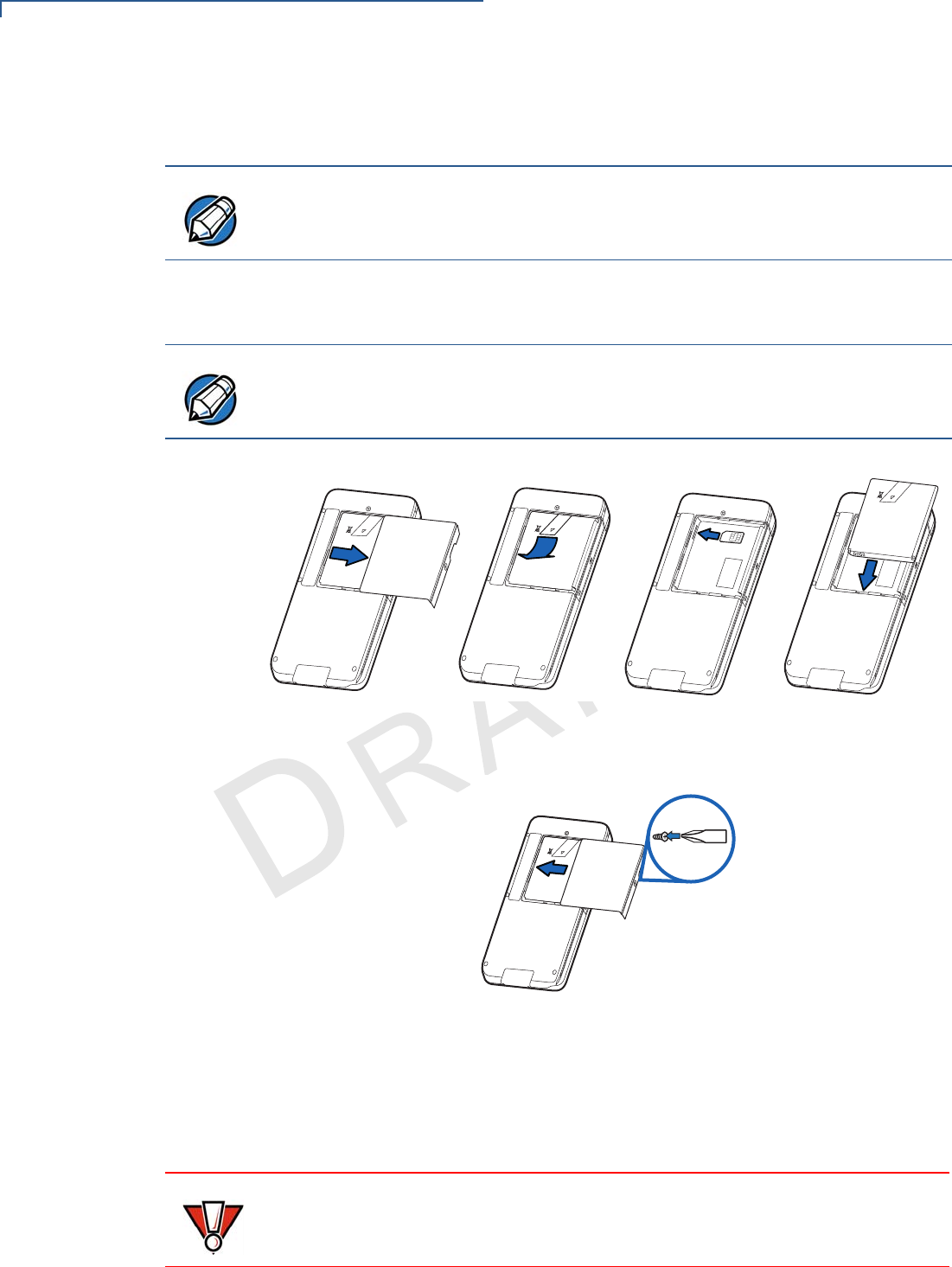
4Remove the battery by gently pulling the plastic tab to access the MSAM
compartment. The MSAM compartment is located on the left side of the
battery compartment.
NOTE
The MSAM compartment is located inside the battery compartment. Remove the
battery to display the access the compartment.
CAUTION
Observe standard precautions when handling electrostatically sensitive devices.
Electrostatic discharges can damage this equipment. Verifone recommends using
a grounded anti-static wrist strap.
NOTE
Not all applications require the use of an MSAM card.
05,,
+
-
DEVICE SETUP
Examining e265 Device Features
14 E265 INSTALLATION GUIDE
VERIFONE
CONFIDENTIAL
REVISION A.6
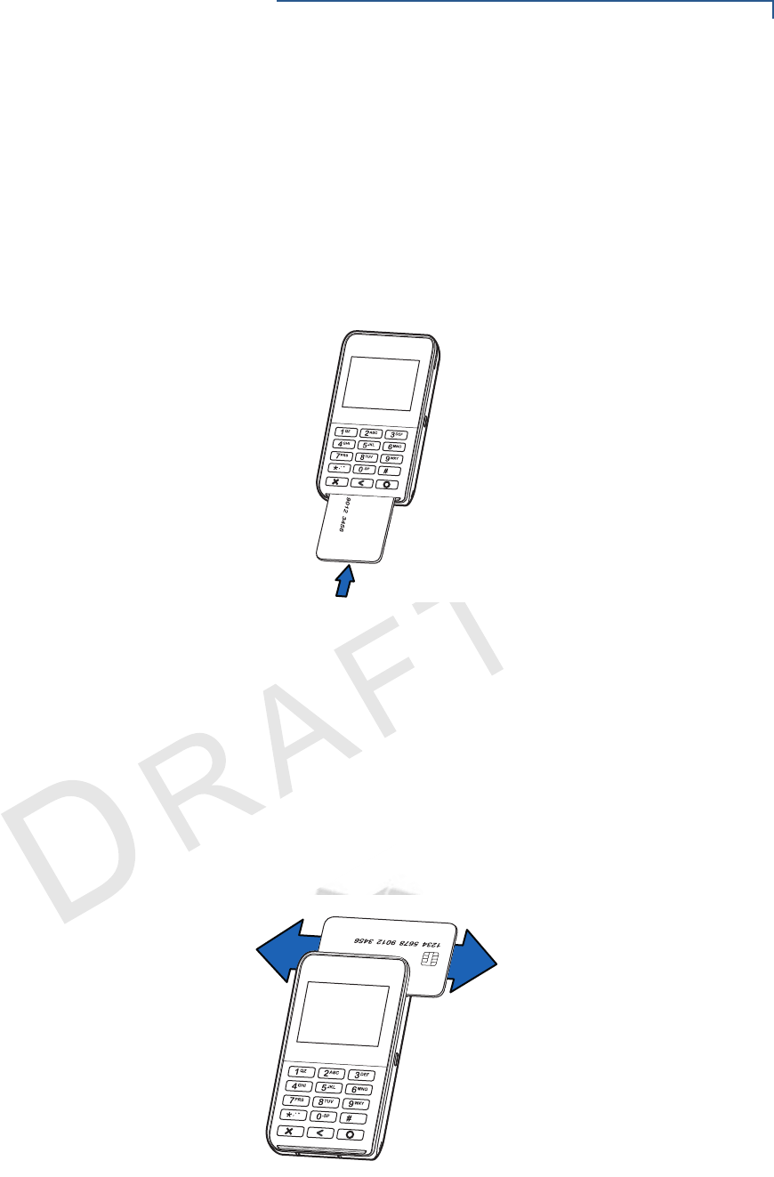
5Insert the MSAM card with the gold contacts facing up. Make sure that the
MSAM card is fully inserted to be able to re-insert the battery.
6Re-insert the battery by aligning the gold contacts in the battery with the pins
on the e265 device.
Figure 5 Inserting an MSAM Card
7Place the battery cover back and tighten the screw.
Figure 6 Returning the Battery Cover
Manually Starting
and Resetting the
e265
To turn on the e265, press and hold the Enter key for at least five seconds.
The Reset Button is located just above the Power LED Indicator.
NOTE
The MSAM slot has a spring-loading mechanism. To remove an MSAM card from
the slot, simply press the card into the slot and then release to eject the card.
NOTE
The plastic tab attached to the battery allows you to easily remove the battery from
the compartment. Make sure that the plastic tab is still visible after insertion.
05,,
+
-
05,,
+
-
05,,
+
-
05,,
+
-
CAUTION
The Reset Button resets the device to its initialized state. NEVER use the Reset
Button unless instructed by a Verifone support representative.
DEVICE SETUP
Examining e265 Device Features
E265 INSTALLATION GUIDE 15
VERIFONE
CONFIDENTIAL
REVISION A.6
Connecting the e265
to a Power Source
or a Host Computer
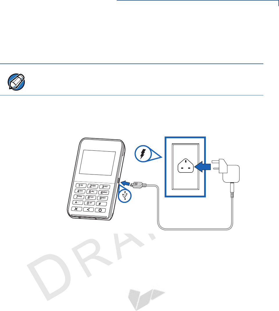
Plug the wall-mount charger to an external power source and connect it to the
e265 to charge the device. You can also connect the e265 to a computer to
synchronize data and/or charge the device.
To Connect the e265
to a Wall-mount
Charger
1Plug the Verifone-certified wall-mount charger into a wall outlet or powered
surge protector.
2Insert the Micro-USB cable into the port located on the side of the e265.
Figure 7 Connecting the e265 to a Wall-mount Charger
NOTE
Charge the e265 device for eight hours before initial use.
4
DEVICE SETUP
Examining e265 Device Features
16 E265 INSTALLATION GUIDE
VERIFONE
CONFIDENTIAL
REVISION A.6
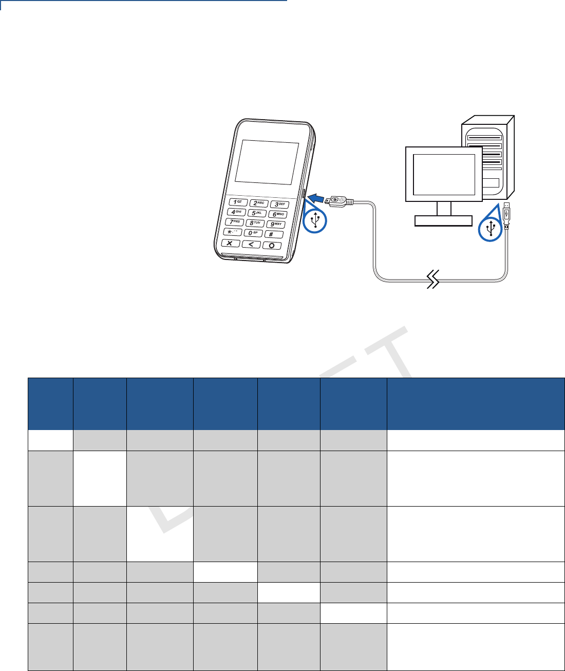
To Connect the e265
to a Host Computer
via Micro-USB
1Connect the Micro-USB cable into the port located on the side of the e265.
2Connect the other end of the Micro-USB cable into the host computer’s USB
port.
Figure 8 Connecting the e265 to a Host Computer
Color Behavior
The following table shows the behavior of the LEDs during various system power
states.
Sleep Battery
Low
Battery
Extremely
Low
Battery
Charging
Charging
Timer
Fault
Normal
Operation LED Behavior
YGreen, blinks every 4 seconds
YRed, 1Hz rate, 50% duty cycle
(Battery low condition: battery
voltage <3.7V)
YRed, 4Hz rate, 50% duty cycle
(Battery extremely low condition:
battery voltage <3.6V)
YOrange, 1Hz rate, 50% duty cycle
YOrange, on continuously
YGreen, on continuously
LEDs are turned OFF when
charging the e265 on a gang
charger
DEVICE SETUP
Examining e265 Device Features
E265 INSTALLATION GUIDE 17
VERIFONE
CONFIDENTIAL
REVISION A.6
Using the Smart
Card Reader
The smart card transaction procedure may vary from one application to another.
Verify the procedure with your application provider before performing a smart card
transaction.
To conduct a smart
card transaction 1Position the smart card with the contacts facing in the same direction as the
keypad.
2Insert the card into the reader slot in a smooth, continuous motion until it seats
firmly.
Figure 9 Inserting a Smart Card
3Wait for the application to indicate a completed transaction before removing
the card. Premature card removal invalidates the transaction.
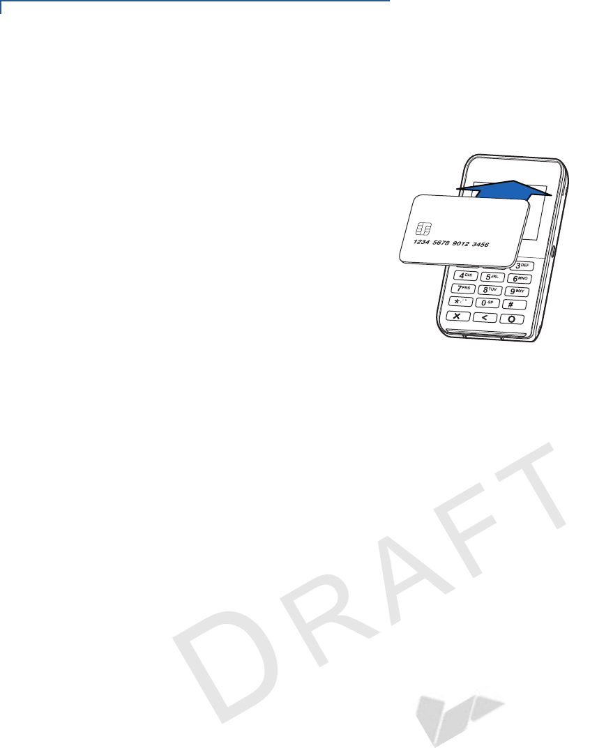
Using the Magnetic
Stripe Reader
Use the magnetic stripe reader to perform credit and debit card transactions.
To conduct a credit/
debit card transaction 1Position the card with the magnetic stripe facing backwards.
2To ensure a proper read of the magnetic swipe card, insert the magnetic card
from the top of the device, as shown in Figure 10.
Figure 10 Using Magnetic Stripe Card
3Swipe the card through the magnetic card reader.
DEVICE SETUP
Examining e265 Device Features
18 E265 INSTALLATION GUIDE
VERIFONE
CONFIDENTIAL
REVISION A.6
Using the CTLS
Reader
The e265 supports contactless credit or debit card transactions. To perform a
contactless transaction, gently tap the card or hold the card against the surface of
the contactless antenna, located above the keypad and LCD with a CTLS symbol.
Figure 11 Using the CTLS Reader

E265 INSTALLATION GUIDE 19
VERIFONE
CONFIDENTIAL
REVISION A.6
CHAPTER 3
Specifications
This chapter discusses power requirements, dimensions, and other specifications
of the e265 device.
Power
Charging via Micro-USB to computer system or Verifone-certified power adapter:
5 V DC, 2 A
Temperature
•Operating Temperature: -5° to 40°C (23° to 104°F)
•Relative humidity: 5% to 95%; RH non-condensing
External
Dimensions
•Length: 130 mm
•Width: 71 mm
•Depth: 14.5 mm

SPECIFICATIONS
External Dimensions
20 E265 INSTALLATION GUIDE
VERIFONE
CONFIDENTIAL
REVISION A.6
E265 INSTALLATION GUIDE 21
VERIFONE
CONFIDENTIAL
REVISION A.6
CHAPTER 4
Maintenance
The e265 device has no user-maintainable parts.
Cleaning the
Device
To clean the device, use a clean cloth slightly dampened with water and a drop or
two of mild soap. For stubborn stains, use alcohol or an alcohol-based cleaner.
Smart Card
Reader
Do not attempt to clean the smart card reader. Doing so may void any warranty.
For smart card reader service, contact your Verifone distributor or service
provider.
CAUTION
Never use thinner, trichloroethylene, or ketone-based solvents – they may cause
deterioration of plastic or rubber parts.
Do not spray cleaners or other solutions directly onto the keypad or device
display.

MAINTENANCE
Smart Card Reader
22 E265 INSTALLATION GUIDE
VERIFONE
CONFIDENTIAL
REVISION A.6

E265 INSTALLATION GUIDE 23
VERIFONE
CONFIDENTIAL
REVISION A.6
CHAPTER 5
Verifone Service and Support
For e265 problems, contact your local Verifone representative or service provider.
For e265 product service and repair information:
•USA – Verifone Service and Support Group, 1-800-Verifone (837-4366),
Monday - Friday, 8 A.M. - 8 P.M., Eastern time
•International – Contact your Verifone representative
Returning a
Device for
Service
Before returning a e265, you must obtain an MRA number. The following
procedure describes how to return one or more devices for repair or replacement
(U.S. customers only).
To return a device for
service 1Get the following information from the printed labels at the back of each e265
to be returned:
•Product ID, including the model and part number. For example, “e265” and
“M087-XXX-XXX-XXX.”
•Serial number (S/N nnn-nnn-nnn)
2Obtain the MRA number(s) by completing one of the following:
aCall Verifone toll-free within the United States at 1-800-Verifone and follow
the automated menu options.
•Select the MRA option from the automated message. The MRA
department is open Monday to Friday, 8 A.M.–8 P.M., Eastern Time.
•Give the MRA representative the information you gathered in Step 1.
If the list of serial numbers is long, you can fax the list, along with the
information gathered in Step 1, to the MRA department at 727-953-
4172 (U.S.).
bAddress a fax to “Verifone MRA Dept.” with the model and part number(s)
•Include a telephone number where you can be reached and your fax
number.
cComplete the Inquiry Contact Form at http://www.verifone.com/
aboutus/contact/contact_form.cfm.
NOTE
Customers outside the United States are advised to contact their local Verifone
representative for assistance regarding service, return, or replacement of devices
and accessories.

VERIFONE SERVICE AND SUPPORT
Accessories and Documentation
24 E265 INSTALLATION GUIDE
VERIFONE
CONFIDENTIAL
REVISION A.6
•Address the Subject box with to “Verifone MRA Dept.”
•Reference the model and part number in the Note box.
3Describe the problem(s).
4Provide the shipping address where the repaired or replacement unit must be
returned.
5Keep a record of the following items:
•Assigned MRA number(s).
•Verifone serial number assigned to the e265 you are returning for service
or repair (device serial numbers are located at the back of the unit.
•Shipping documentation, such as air bill numbers used to trace the
shipment.
•Model(s) returned (model numbers are located on the Verifone label at the
back of the e265).
Accessories and
Documentation
Verifone produces the following accessories and documentation for the
e265. When ordering, please take note of the part number.
•Verifone online store at www.store.verifone.com
•USA – Verifone Customer Development Center, 800-Verifone (837-4366),
Monday - Friday, 7 A.M. - 8 P.M., Eastern time
•International – Contact your Verifone representative
Accessories
Documentation
Battery Pack
Instructions
Dispose of the battery pack in accordance with all national, state, and local laws
and regulations as regionally required. Some batteries may be recycled and may
be accepted for disposal at local recycling centers. Please refer to Installing/
Replacing an MSAM Card for instructions on battery removal and insertion.
NOTE
One MRA number must be issued for each e265 you return to Verifone, even if
you are returning several of the same model.
Verifone Certified Power Adapter PWR087-300-01-A
Verifone Cleaning Kit 02746-01
e265 Certifications and Regulations Sheet VPN DOC087-301-EN
e265 Quick Installation Guide VPN DOC087-302-EN
e265 Web site www.paywaremobile.com
CAUTION
There is a risk of explosion if the battery is replaced by an incorrect type.

E265 INSTALLATION GUIDE 25
VERIFONE
CONFIDENTIAL
REVISION A.6
CHAPTER 6
Troubleshooting
Guidelines
The troubleshooting guidelines provided in the following section are included to
help you install and configure your e265 successfully. Typical examples of
malfunction you may encounter while operating your e265 and steps you can take
to resolve them are listed in this chapter.
If the problem persists even after performing the outlined guidelines or if the
problem is not described below, contact your local Verifone representative for
assistance.
Device Does Not
Start
•Ensure that the battery charge state is not below the critically low level.
•Recharge the battery.
•Check if the battery is properly inserted. Remove the screw from the battery
cover. Slide the cover outwards, away from the device and the check if the
device and battery contacts are aligned.
Device Display
Does Not Show
Correct/
Readable Info
•Recharge the battery.
•Connect the e265 into a known-good power supply (if available) to see if this
clears the problem.
•If the problem persists, contact your local Verifone representative for
assistance.
NOTE
The e265 comes equipped with tamper-evident labels. The e265 unit contains no
user serviceable parts. Do not, under any circumstance, attempt to disassemble
the device. Perform only those adjustments or repairs specified in this guide. For
all other services, contact your local Verifone service provider. Service conducted
by parties other than authorized Verifone representatives may void any warranty.
CAUTION
Use only a Verifone-supplied power pack. Using an incorrectly rated power
supply may damage the device or cause it not to work as specified. Before
troubleshooting, ensure that the power supply being used to power the device
matches the requirements specified at the bottom of the device. (See
Specifications, for detailed power supply specifications.) Obtain the appropriately
rated power supply before continuing with troubleshooting.

TROUBLESHOOTING GUIDELINES
Blank Display
26 E265 INSTALLATION GUIDE
VERIFONE
CONFIDENTIAL
REVISION A.6
Blank Display
When the e265 display screen does not show correct or clearly readable
information:
•Check device power connection.
•Remove and reapply power to the device. To do this, press and hold the
power/reset button.
•If the problem persists, contact your local Verifone service provider.
Keypad Does
Not Respond
If the keypad does not respond properly:
•Check the device display. If it displays the wrong character or nothing at all
when you press a key, follow the steps outlined in Transactions Fail To
Process.
•If the problem persists, contact your local Verifone representative.
•Place a paper clip or a similar tool in the hole located on the side of the device
to press the Reset Button.
Transactions
Fail To Process
There are several reasons why the device may not be processing transactions.
Use the following steps to troubleshoot failures.
Check the Magnetic Card Reader
•Perform a test transaction using one or more different magnetic stripe cards to
ensure the problem is not a defective card.
•The side of the card where the black magnetic stripe is should be visible.
Insert the magnetic stripe card from the top of the device going downwards in
a smooth and continuous manner (see Figure 10).
Check the Smart Card Reader
•Perform a test transaction using several different smart cards to ensure the
problem is not a defective card.
•Ensure that the card is inserted correctly and that the card is not removed
prematurely.
•Ensure the MSAM cards are properly inserted (see Installing/Replacing an
MSAM Card).
•Contact your Verifone distributor or service provider.
CAUTION
Do NOT paste anything on the keypad surface to avoid malfunction.

TROUBLESHOOTING GUIDELINES
Transactions Fail To Process
E265 INSTALLATION GUIDE 27
VERIFONE
CONFIDENTIAL
REVISION A.6