Verifone OMNI3750G Point of Sale Terminal User Manual 22399 book
VeriFone Inc Point of Sale Terminal 22399 book
Verifone >
Users Manual Revised

VeriFone Part Number 22399, Revision B
VERIX
OPERATING
ENVIRONMENT
SOFTPAY
E-PAYMENT
APPLICATION
VERIX
DEVELOPMENT
TOOLS
DEVELOPER
TOOLKIT
VERISHIELD
SECURITY
ARCHITECTURE
OMNI 33XX
MULTI-APPLICATION
APPLIANCES
VERICENTRE
APPLIANCE
MANAGEMENT
SUITE
VERIX
MANAGEMENT
MULTI-APP
CONDUCTOR
SYSTEM
MULITPLE APPLICATION
OMNI 37XX
HAND-OVER-COUNTER
MULTI-APPLICATION
APPLIANCES
Omni 37xx
Installation Guide
All rights reserved. No part of the contents of this document may be reproduced or transmitted in any form without the written
permission of VeriFone, Inc.
The information contained in this document is subject to change without notice. Although VeriFone has attempted to ensure the
accuracy of the contents of this document, this document may include errors or omissions. The examples and sample programs are
for illustration only and may not be suited for your purpose. You should verify the applicability of any example or sample program
before placing the software into productive use. This document, including without limitation the examples and software programs, is
supplied “As-Is.”
VeriFone, Inc.
2455 Augustine Drive
Santa Clara CA 95054-3002
www.verifone.com
VeriFone Part Number 22399, Revision B
Omni 37xx Installation Guide
© 2002 VeriFone, Inc.
VeriFone, the VeriFone logo, and Omni are registered trademarks of VeriFone. Other brand names or trademarks associated with
VeriFone’s products and services are trademarks of VeriFone, Inc.
All other brand names and trademarks appearing in this manual are the property of their respective holders.
Comments? Please e-mail all comments in this document to Tell_Us_More@VeriFone.com

OMNI 37XX INSTALLATION GUIDE 3
CONTENTS
PREFACE . . . . . . . . . . . . . . . . . . . . . . . . . . . . . . . . . . . . . . . 5
Audience. . . . . . . . . . . . . . . . . . . . . . . . . . . . . . . . . . . . . . . . . . . . . . . . . . . . . . . . 5
Organization . . . . . . . . . . . . . . . . . . . . . . . . . . . . . . . . . . . . . . . . . . . . . . . . . . . . . 5
Related Documentation . . . . . . . . . . . . . . . . . . . . . . . . . . . . . . . . . . . . . . . . . . . . 5
Conventions Used in This Guide . . . . . . . . . . . . . . . . . . . . . . . . . . . . . . . . . . . . . 5
CHAPTER 1
Terminal Overview Omni 37xx . . . . . . . . . . . . . . . . . . . . . . . . . . . . . . . . . . . . . . . . . . . . . . . . . . . . . . 7
Features and Benefits. . . . . . . . . . . . . . . . . . . . . . . . . . . . . . . . . . . . . . . . . . . 8
Exceptional Ease Of Use. . . . . . . . . . . . . . . . . . . . . . . . . . . . . . . . . . . . . . 8
Countertop Performance in a “Hand-Over” Design . . . . . . . . . . . . . . . . . . 8
True Multi-Application Capability . . . . . . . . . . . . . . . . . . . . . . . . . . . . . . . . 8
CHAPTER 2
Terminal Setup Select Terminal Location . . . . . . . . . . . . . . . . . . . . . . . . . . . . . . . . . . . . . . . . . . . 9
Ease of Use . . . . . . . . . . . . . . . . . . . . . . . . . . . . . . . . . . . . . . . . . . . . . . . . . . 9
Environmental Factors . . . . . . . . . . . . . . . . . . . . . . . . . . . . . . . . . . . . . . . . . . 9
Electrical Considerations . . . . . . . . . . . . . . . . . . . . . . . . . . . . . . . . . . . . . . . 10
Unpack the Shipping Carton. . . . . . . . . . . . . . . . . . . . . . . . . . . . . . . . . . . . . . . . 10
Examine Terminal Features . . . . . . . . . . . . . . . . . . . . . . . . . . . . . . . . . . . . . . . . 11
Front Panel . . . . . . . . . . . . . . . . . . . . . . . . . . . . . . . . . . . . . . . . . . . . . . . . . . 11
Back Panel . . . . . . . . . . . . . . . . . . . . . . . . . . . . . . . . . . . . . . . . . . . . . . . . . . 12
Establish Telephone Line Connections . . . . . . . . . . . . . . . . . . . . . . . . . . . . . . . 13
Install Paper Roll . . . . . . . . . . . . . . . . . . . . . . . . . . . . . . . . . . . . . . . . . . . . . . . . 13
Install/Replace MSAM Cards . . . . . . . . . . . . . . . . . . . . . . . . . . . . . . . . . . . . . . . 16
Connect Optional Device(s) . . . . . . . . . . . . . . . . . . . . . . . . . . . . . . . . . . . . . . . . 18
Connect PIN Pad, Smart Card Reader, or Bar Code Wand . . . . . . . . . . . . . 18
Connect Check Reader. . . . . . . . . . . . . . . . . . . . . . . . . . . . . . . . . . . . . . . . . 19
External Printers Supported . . . . . . . . . . . . . . . . . . . . . . . . . . . . . . . . . . . . . 20
Connect Terminal Power Pack. . . . . . . . . . . . . . . . . . . . . . . . . . . . . . . . . . . . . . 20
Routing The Cables Using Wire Clips . . . . . . . . . . . . . . . . . . . . . . . . . . . . . . . . 22
Smart Card Transaction . . . . . . . . . . . . . . . . . . . . . . . . . . . . . . . . . . . . . . . . . . . 22
Magnetic Card Reader Use . . . . . . . . . . . . . . . . . . . . . . . . . . . . . . . . . . . . . . . . 23
CHAPTER 3
Specifications Power . . . . . . . . . . . . . . . . . . . . . . . . . . . . . . . . . . . . . . . . . . . . . . . . . . . . . . 25
DC Power Pack. . . . . . . . . . . . . . . . . . . . . . . . . . . . . . . . . . . . . . . . . . . . . . . 25
Temperature . . . . . . . . . . . . . . . . . . . . . . . . . . . . . . . . . . . . . . . . . . . . . . . . . 25
External Dimensions. . . . . . . . . . . . . . . . . . . . . . . . . . . . . . . . . . . . . . . . . . . 25
Weight. . . . . . . . . . . . . . . . . . . . . . . . . . . . . . . . . . . . . . . . . . . . . . . . . . . . . . 25
CHAPTER 4
Maintenance Cleaning the Terminal . . . . . . . . . . . . . . . . . . . . . . . . . . . . . . . . . . . . . . . . . . . . 27
Smart Card Reader . . . . . . . . . . . . . . . . . . . . . . . . . . . . . . . . . . . . . . . . . . . . . . 27

LIST OF FIGURES
4OMNI 37XX INSTALLATION GUIDE
CHAPTER 5
VeriFone Service
and Support Returning a Terminal for Service . . . . . . . . . . . . . . . . . . . . . . . . . . . . . . . . . . . . 29
Accessories and Documentation . . . . . . . . . . . . . . . . . . . . . . . . . . . . . . . . . . . . 30
Download Cables . . . . . . . . . . . . . . . . . . . . . . . . . . . . . . . . . . . . . . . . . . . . . 30
Cables for Optional Peripherals . . . . . . . . . . . . . . . . . . . . . . . . . . . . . . . . . . 30
Telephone Line Cord . . . . . . . . . . . . . . . . . . . . . . . . . . . . . . . . . . . . . . . . . . 31
Power Pack. . . . . . . . . . . . . . . . . . . . . . . . . . . . . . . . . . . . . . . . . . . . . . . . . . 31
Wire clip . . . . . . . . . . . . . . . . . . . . . . . . . . . . . . . . . . . . . . . . . . . . . . . . . . . . 31
Thermal Printer Paper. . . . . . . . . . . . . . . . . . . . . . . . . . . . . . . . . . . . . . . . . . 31
Paper Roll Spindle . . . . . . . . . . . . . . . . . . . . . . . . . . . . . . . . . . . . . . . . . . . . 31
VeriFone Cleaning Kit. . . . . . . . . . . . . . . . . . . . . . . . . . . . . . . . . . . . . . . . . . 31
Documentation . . . . . . . . . . . . . . . . . . . . . . . . . . . . . . . . . . . . . . . . . . . . . . . 31
CHAPTER 6
Troubleshooting
Guidelines Blank Display . . . . . . . . . . . . . . . . . . . . . . . . . . . . . . . . . . . . . . . . . . . . . . . . . . . 33
Terminal Does Not Dial Out . . . . . . . . . . . . . . . . . . . . . . . . . . . . . . . . . . . . . . . . 33
Printer Does Not Print. . . . . . . . . . . . . . . . . . . . . . . . . . . . . . . . . . . . . . . . . . . . . 34
Printer Paper Jam. . . . . . . . . . . . . . . . . . . . . . . . . . . . . . . . . . . . . . . . . . . . . . . . 34
Peripherals Device Does Not Work . . . . . . . . . . . . . . . . . . . . . . . . . . . . . . . . . . 34
Keypad Does Not Respond . . . . . . . . . . . . . . . . . . . . . . . . . . . . . . . . . . . . . . . . 35
Transactions Fail To Process. . . . . . . . . . . . . . . . . . . . . . . . . . . . . . . . . . . . . . . 35
Check Magnetic Card Reader . . . . . . . . . . . . . . . . . . . . . . . . . . . . . . . . . 35
Check Smart Card Reader. . . . . . . . . . . . . . . . . . . . . . . . . . . . . . . . . . . . 35
Check Telephone Line. . . . . . . . . . . . . . . . . . . . . . . . . . . . . . . . . . . . . . . 35
INDEX . . . . . . . . . . . . . . . . . . . . . . . . . . . . . . . . . . . . . . . . .37
LIST OF FIGURES
Figure 1 Omni 37xx Product Components . . . . . . . . . . . . . . . . . . . . . . . .10
Figure 2 Omni 37xx Terminal Features (Front Panel) . . . . . . . . . . . . . . .11
Figure 3 Connection Ports (Back Panel) . . . . . . . . . . . . . . . . . . . . . . . . .12
Figure 4 Direct Telephone Connection . . . . . . . . . . . . . . . . . . . . . . . . . .13
Figure 5 Printer Latch Button . . . . . . . . . . . . . . . . . . . . . . . . . . . . . . . . . .14
Figure 6 Removing Partial Paper Roll . . . . . . . . . . . . . . . . . . . . . . . . . . .15
Figure 7 Loading Paper Roll . . . . . . . . . . . . . . . . . . . . . . . . . . . . . . . . . .15
Figure 8 Closing Paper Roll Cover . . . . . . . . . . . . . . . . . . . . . . . . . . . . . .16
Figure 9 MSAM Compartment Door and Locking Screw . . . . . . . . . . . . .17
Figure 10 MSAM Cardholder Close-Up . . . . . . . . . . . . . . . . . . . . . . . . . . .17
Figure 11 Using an MSAM Cardholder . . . . . . . . . . . . . . . . . . . . . . . . . . .17
Figure 12 Smart Card Reader Connection . . . . . . . . . . . . . . . . . . . . . . . . .19
Figure 13 CR 600 Check Reader Connection . . . . . . . . . . . . . . . . . . . . . .20
Figure 14 Omni 37xx Power Pack Connection . . . . . . . . . . . . . . . . . . . . .21
Figure 15 Routing Cables Using Cable Wires . . . . . . . . . . . . . . . . . . . . . .22
Figure 16 Inserting the Smart Card . . . . . . . . . . . . . . . . . . . . . . . . . . . . . .23
Figure 17 Using the Magnetic Card Reader . . . . . . . . . . . . . . . . . . . . . . . .23
Figure 18 Information Label on Terminal Bottom . . . . . . . . . . . . . . . . . . . .30
LIST OF TABLES
Table 1 Document Conventions . . . . . . . . . . . . . . . . . . . . . . . . . . . . . . . . 5
Table 2 Optional Devices Supported . . . . . . . . . . . . . . . . . . . . . . . . . . . 18

OMNI 37XX INSTALLATION GUIDE 5
PREFACE
This guide is your primary source of information for setting up and installing the
Omni 37xx family of terminals.
Audience This guide is useful for anyone installing and configuring the Omni 37xx terminal.
Basic description of the terminal features are also provided.
Organization This guide is organized as follows:
Chapter 1, Terminal Overview, Provides an overview of the Omni 37xx family of
terminals.
Chapter 2, Terminal Setup. Explains how to set up and install the Omni 37xx
terminal. It tells you how to select a location, establish power and telephone line
connections, and how to configure optional peripheral devices.
Chapter 3 Specifications. Discusses power requirements and dimensions of the
Omni 37xx terminal.
Chapter 4, Maintenance. Explains how to maintain your Omni 37xx terminal.
Chapter 5, VeriFone Service and Support. Provides information on contacting
your local VeriFone representative or service provider. You will also find
information on how to order accessories or documentation from the VeriFone.
Chapter 6, Troubleshooting Guidelines. Provides troubleshooting guidelines,
should you encounter a problem in terminal installation and configuration.
Related
Documentation
To learn more about Omni 37xx, refer the following set of documents:
•Omni 3750 Quick Installation Guide, VeriFone Part Number (VPN) - 22398,
Rev. C
•Omni 37xx Certifications and Regulations, VPN - 22429, Rev. B
•Verix Programmer’s Manual, VPN - 22380, Rev. E
Conventions
Used in This
Guide
Various conventions are used to help you quickly identify special formatting. The
following table describes these conventions and provides examples of their use.
Table 1 Document Conventions
Convention Meaning Example
Blue Text in blue indicates terms that are cross
referenced.
See Conventions Used in This Guide.
Italics Italic typeface indicates book titles or
emphasis.
You must install a roll of thermal-sensitive
paper in the printer.

PREFACE
Conventions Used in This Guide
6OMNI 37XX INSTALLATION GUIDE
ScreenText - PRE ScreenText format is used while specifying
onscreen text, such as text that you would
enter at a command prompt, or to provide an
URL.
http://www.verifone.com
The pencil icon is used to highlight important
information.
RS232-type devices do not work with the
PIN Pad port.
The caution symbol indicates hardware or
software failure, or loss of data.
The terminal is not waterproof or
dustproof, and is intended for indoor use
only.
The lighting symbol is used as a warning
when bodily injury might occur.
Due to risk of shock do not use the
terminal near water.
Table 1 Document Conventions (continued)
Convention Meaning Example
NOTE
CAUTION
WARNING

OMNI 37XX INSTALLATION GUIDE 7
CHAPTER 1
Terminal Overview
This chapter provides a brief description of VeriFone’s Omni 37xx family of
terminals. The Omni 37xx family includes Omni 3700, Omni 3740, and
Omni 3750 terminals.
Omni 37xx The Omni 37xx terminal series represents the shape of things to come in
e-payment. The bold ergonomic design is sleek and stylish, offering countertop
power and 32-bit performance in an integrated terminal that can be handed to the
consumer for input. In addition, the Omni 37xx family serves as the entry point to
VeriFone’s acclaimed multi-application platform–with the capability to securely
support payment and value-added applications on a single terminal.
The Omni 37xx provides the right combination of features and functions at the
right price. This includes a vertical magnetic-stripe card reader, smart card reader,
integrated PINpad, and a quiet, fast, integrated thermal printer.
NOTE VeriFone ships variants of the Omni 37xx terminal for different markets. Your
terminal may have a different configuration. The following devices may or may not
be present: a smart card reader, a printer, and/or zero, two, or four SAM
cardholders.
Features At a Glance
•Delivers power and usability in a
convenient “hand-over” design.
•Securely supports and runs payment
and value-added applications.
•Multi-application operating
environment.
•Offers unsurpassed performance on
EMV smartcard transactions.
•32-bit processing and multi-tasking
capabilities.
•Security architecture meets
specifications for PIN-entry devices
(PED) and sophisticated file
authentication.

TERMINAL OVERVIEW
Omni 37xx
8OMNI 37XX INSTALLATION GUIDE
Features and
Benefits Exceptional Ease Of Use
•Bold design is sleek, stylish, and lightweight for conveniently handing terminal
to consumer for PIN entry or other input.
•Intuitive ATM-style interface, large 8 line x 21 character backlit display with
split screen capabilities, large keys, and extra-size menu prompts simplify
training and reduce calls to the Help Desk.
•Integrated high-speed thermal printer simplifies paper loading and virtually
eliminates paper jams.
•Triple-track, high-coercivity card reader handles most magnetic stripe cards.
Countertop Performance in a “Hand-Over” Design
•32-bit processing and multi-tasking capabilities make short work of payment,
payment-related, and value-added applications.
•Exceptional graphics-handling capabilities of display and printer quickly render
logos, graphical fonts, and character-based languages.
•VeriCenter Appliance Management Suite employs advanced file compression
to streamline downloads of application software simultaneously to hundreds of
terminals.
•Integrated PINpad offers added convenience to handle PIN-based
applications.
•Ensures uncompromising reliability from VeriFone, the worldwide leader in
e-payment.
True Multi-Application Capability
•1.5 MB of memory and Verix’s dynamic memory allocation support two or
three typical-sized applications on a single terminal.
•Primary smart card reader and two Security Access Modules (SAMs)
safeguard sensitive financial data and support multiple smart card schemes.
•Omni 37xx family of terminals and SoftPay EMV software have received EMV
Level 1 and Level 2 Type Approval for smart card solutions. The Verix EMV
Library provides efficient development of other EMV-compliant applications.
•VeriShield security architecture meets published specifications for PIN-entry
devices (PED) and provides sophisticated file authentication, which prevents
execution of unauthorized software on Omni 37xx terminals.

OMNI 37XX INSTALLATION GUIDE 9
CHAPTER 2
Terminal Setup
This chapter describes terminal setup procedure. You will learn how to:
•Select a location and protect the terminal from adverse Environmental
Factors. See Select Terminal Location.
•Unpack the shipping carton. See Unpack the Shipping Carton.
•Examine terminal features. See Examine Terminal Features.
•Establish telephone line connections. See Establish Telephone Line
Connections.
•Install paper roll in the printer. See Install Paper Roll.
•Configure optional peripheral devices. See Connect Optional Device(s).
•Establish power connections. See Connect Terminal Power Pack.
•Route cables using wire clips. See Routing The Cables Using Wire Clips.
•Conduct smart card, or credit/debit transactions. See Smart Card Transaction
and Magnetic Card Reader Use.
Select Terminal
Location
Follow the guidelines described in the following section while selecting a location
for your terminal.
Ease of Use • Select a location convenient for both merchant and cardholder.
•Select a flat support surface, such as a countertop or table.
•Select a location near a power outlet and a telephone/modem line connection.
For safety, do not string the power cable in a walkway or place across a
walkway on the floor.
Environmental
Factors •Do not use the terminal where there is high heat, dust, humidity, moisture, or
caustic chemicals or oils.
•Keep the terminal away from direct sunlight and anything that radiates heat,
such as a stove or a motor.
•Do not use the terminal outdoors.
CAUTION The terminal is not waterproof or dustproof, and is intended for indoor use only.
Any damage to the unit from exposure to rain or dust may void any warranty.
TERMINAL SETUP
Unpack the Shipping Carton
10 OMNI 37XX INSTALLATION GUIDE
Electrical
Considerations •Avoid using this product during electrical storms.
•Avoid locations near electrical appliances or other devices that cause
excessive voltage fluctuations or emit electrical noise (for example, air
conditioners, electric motors, neon signs, high-frequency or magnetic security
devices, or computer equipment).
•Do not use the terminal near water or in moist conditions.
Unpack the
Shipping
Carton
Open the shipping carton and carefully inspect its contents for possible tampering
or shipping damage. The Omni 37xx is a secure product and any tampering may
cause the terminal to cease to function the way it should.
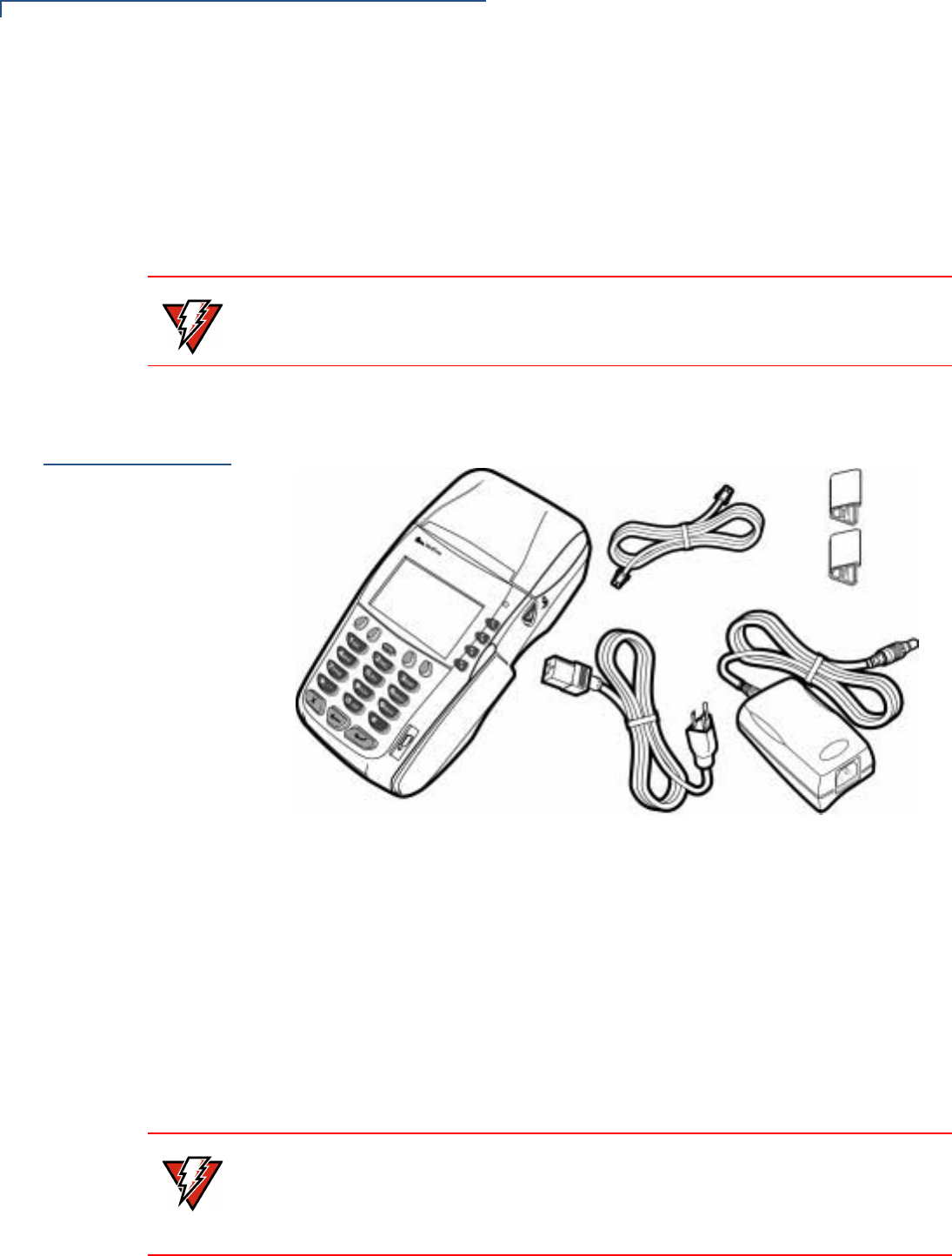
Figure 1 Omni 37xx Product Components
1Remove and inspect the following items (see Figure 1):
•Omni 37xx terminal
•Power pack
•Telephone line cord
•Wire clips
2Remove all plastic wrapping from the terminal and other components.
3Remove the clear protective film from the LCD screen.
WARNING Due to risk of shock or terminal damage, do not use the terminal near water,
including a bathtub, wash bowl, kitchen sink or laundry tub, in a wet basement, or
near a swimming pool.
WARNING Do not use a terminal that has been damaged or tampered.
The Omni 37xx terminal comes equipped with tamper-evident labels. If a label or
component appears damaged, please notify the shipping company and your
VeriFone representative or service provider immediately.
TERMINAL SETUP
Examine Terminal Features
OMNI 37XX INSTALLATION GUIDE 11
4Save the shipping carton and packing material for future repacking or moving
the terminal.
Examine
Terminal
Features
Before you continue the installation process notice the following features of the
Omni 37xx (see Figure 2):
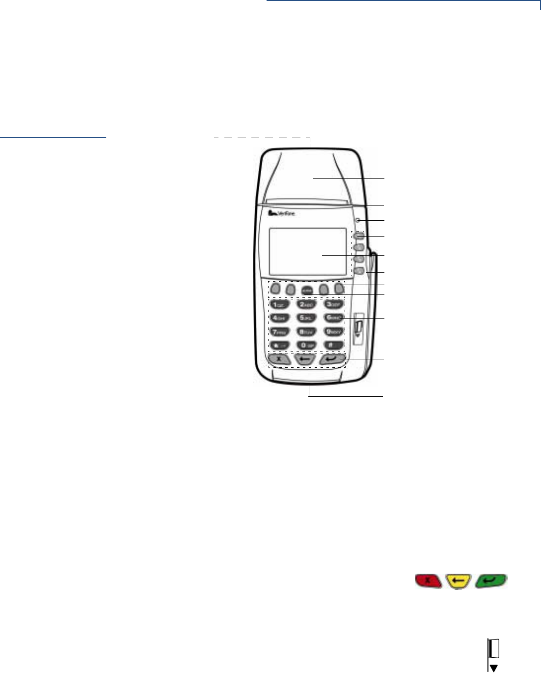
Figure 2 Omni 37xx Terminal Features (Front Panel)
Front Panel The front panel includes the following features:
•An LCD screen.
•Four types of keys:
•A 12-key, telephone-style keypad.
•Four ATM-style function keys, labeled F1 to F4, to the right of the LCD
screen.
•Four unlabeled, programmable function (PF) keys above the keypad.
•Three color-coded function keys below the keypad
(icons at right, left-to-right: CANCEL/OFF,
BACKSPACE, ENTER/ON).
•An ALPHA key centered at the top of the keypad.
•A magnetic card reader, built into the right side. The icon at right
shows the proper swipe direction, with the stripe facing inward,
toward the keypad.
•A green/red indicator LED (Light Emitting Diode) with the following states:
•Steady green light indicates power is ON.
LCD SCREEN
TELEPHONE-STYLE KEYPAD
PROGRAMMABLE FUNCTION KEYS
ATM-STYLE FUNCTION KEYS
MAGNETIC CARD READER
INTERNAL THERMAL
INDICATOR LED
SMART CARD READER
SAM COMPARTMENT
CONNECTION PORTS
(BACK PANEL)
(BACKSIDE)
COLOR-CODED FUNCTION KEYS
PRINTER
PAPER ROLL COVER RELEASE
ALPHA KEY
TERMINAL SETUP
Examine Terminal Features
12 OMNI 37XX INSTALLATION GUIDE
•Slow flashing green (roughly one flash per second) indicates no paper in
the printer.
•Fast flashing green (roughly two flashes per second) indicates a printer
mechanism error.
•Flashing red indicates the terminal is downloading printer-related files.
•An internal thermal printer.
•A smart card reader, built into the terminal’s front side. The icon
shown at right indicates the proper card position and insertion
direction.
•A SAM (security access module) compartment, built into the bottom side of
the terminal. The Omni 37xx terminal contains micromodule-size SAM
(MSAM) cardholders for supporting multiple stored-value card programs or
other merchant card requirements.
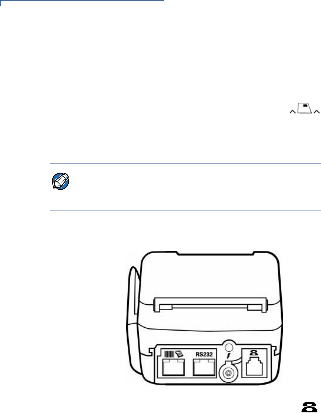
Back Panel If you turn the terminal around and view it from just under the hinges of the paper
roll cover, you will notice different ports that connect the Omni 37xx to a
communications line, optional devices, and the power supply (see Figure 3):
Figure 3 Connection Ports (Back Panel)
•Communications Port can be identified by a telephone-shaped
icon, shown at right. Use this port to connect a telephone to the
Omni 37xx.
NOTE VeriFone ships variants of the Omni 37xx terminal for different markets. Your
terminal may have a different configuration. The following devices may or may not
be present: a smart card reader, a printer; and/or zero, two, or four SAM
cardholders. However, the basic processes described in this guide remains the
same, regardless of the terminal configuration.
TERMINAL SETUP
Establish Telephone Line Connections
OMNI 37XX INSTALLATION GUIDE 13
•Two RJ45-type modular jacks (serial ports) are for attaching optional
peripheral devices.
•RS232 port, icon at right, connects a VeriFone CR 600 check
reader or other peripheral device.
•Bar Code and PIN Pad port, icons at right, connects a PIN pad,
smart card reader, or bar code wand.
•Power connection port that uses a round port with a lock notch for
securely connecting the terminal to a power source. It is identified by
the electrical power icon at right.
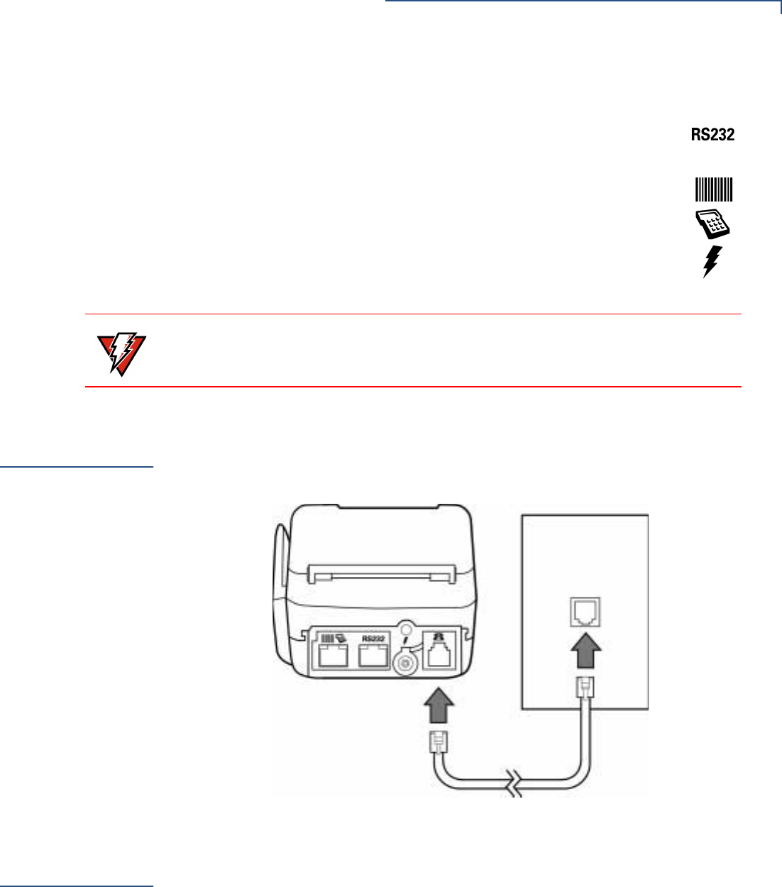
Establish
Telephone Line
Connections
Connect the telephone cord (VeriFone Part Number 00124-17) to the
communication port on the terminal then route it directly to a telephone wall jack
(see Figure 4). This is a direct connection, and the line is dedicated to the
terminal.
Figure 4 Direct Telephone Connection
Install Paper
Roll
A fast, quiet thermal printer is built in to the Omni 37xx. There are no additional
printer cables to connect because the printer receives power directly from the
terminal.
Before you can process transactions that require a receipt or record, you must
install a roll of thermal-sensitive paper in the printer. This procedure is described
in To Install a Paper Roll section.
WARNING Do not connect the terminal to the power supply until all the peripherals are
attached.
TERMINAL SETUP
Install Paper Roll
14 OMNI 37XX INSTALLATION GUIDE
The internal thermal printer uses a roll of single-ply, thermal-sensitive paper
58 millimeters (2.25 inches) wide and about 25-33 meters (82-108 feet) long.
To Install a Paper Roll
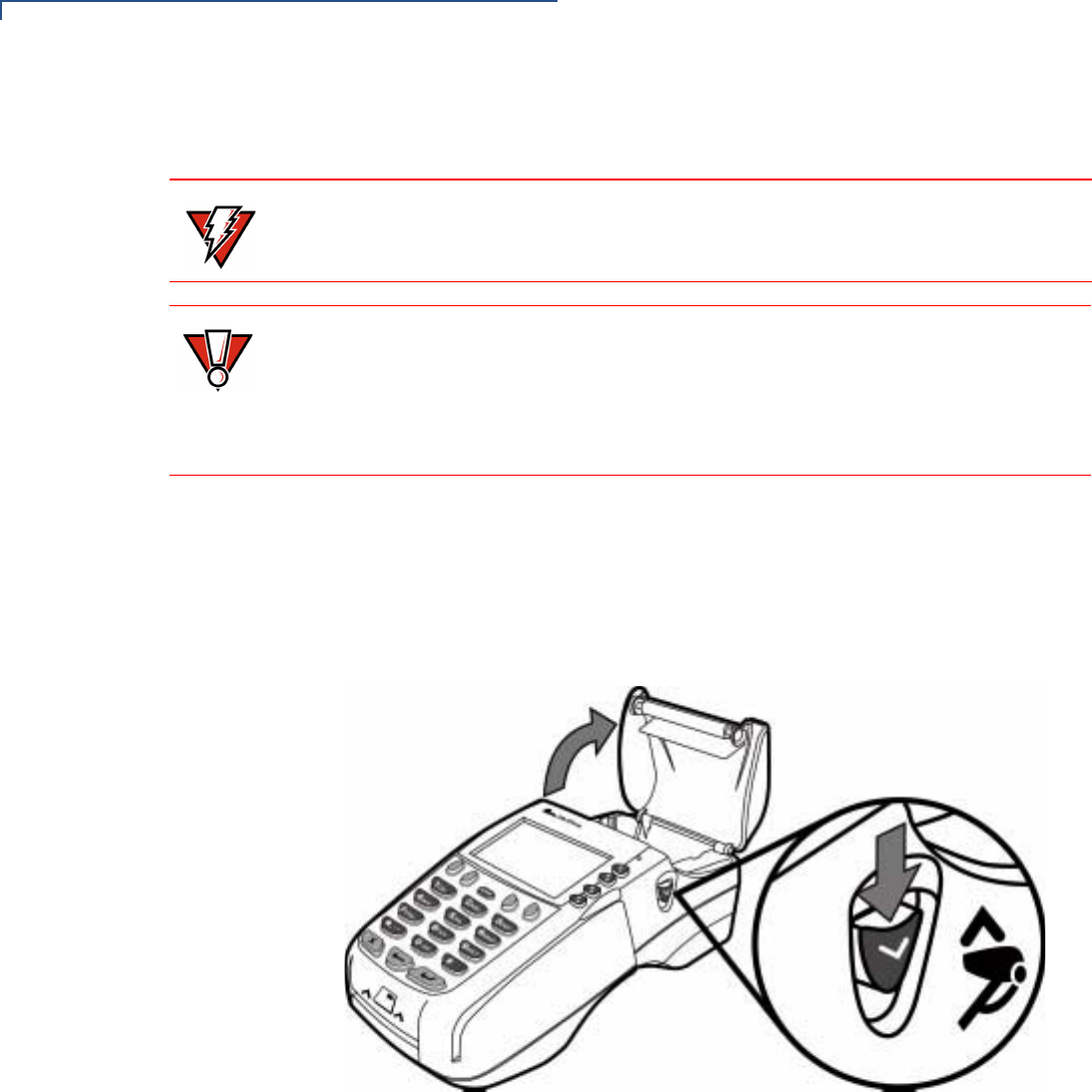
1Turn on the terminal. The green LED indicator will blink on and off, indicating
that the printer needs paper.
2Press the button on the side of the terminal to unlatch the paper roll cover,
then rotate the cover up back on its hinges (see Figure 6).
Figure 5 Printer Latch Button
WARNING Poor-quality paper jams the printer. To order high-quality VeriFone paper, refer the
Accessories and Documentation section.
CAUTION Store thermal paper in a dry, dark area. Handle thermal paper carefully: impact,
friction, temperature, humidity, and oil affect the color and storage characteristics
of the paper.
Never load a roll of paper with folds, wrinkles, tears, or holes at the edges or in the
printing area.
TERMINAL SETUP
Install Paper Roll
OMNI 37XX INSTALLATION GUIDE 15
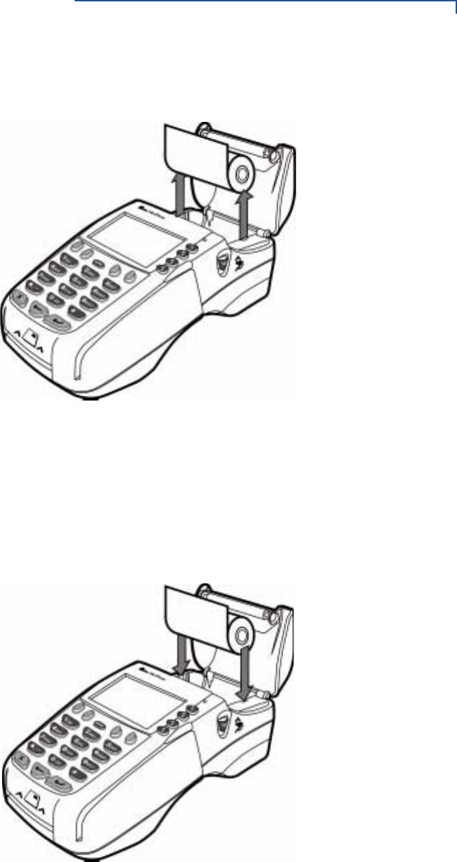
3If there is a partial roll of paper in the printer tray, remove it by lifting it up (see
Figure 6).
Figure 6 Removing Partial Paper Roll
4Loosen the glued leading edge of the paper, or remove the protective strip
from the new roll of paper and cut a straight edge across its leading end.
5Hold the roll so the paper feeds from the bottom of the roll.
6Drop the paper roll into the printer tray, leaving 7 centimeters (about two
inches) of paper sticking up past the serrated metal tear strip (see Figure 7).
Figure 7 Loading Paper Roll
TERMINAL SETUP
Install/Replace MSAM Cards
16 OMNI 37XX INSTALLATION GUIDE
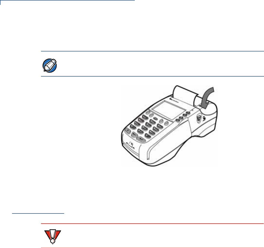
7Close the cover by gently pressing directly on the paper roll cover until it clicks
shut. Allow a small amount of paper to extend outside the cover (see
Figure 8).
Figure 8 Closing Paper Roll Cover
For paper ordering information, refer to the Accessories and Documentation
section.
Install/Replace
MSAM Cards
When you first receive your Omni 37xx terminal, you may need to install one or
more micromodule-size security access module (MSAM) cards, or you may need
to replace old cards with new ones.
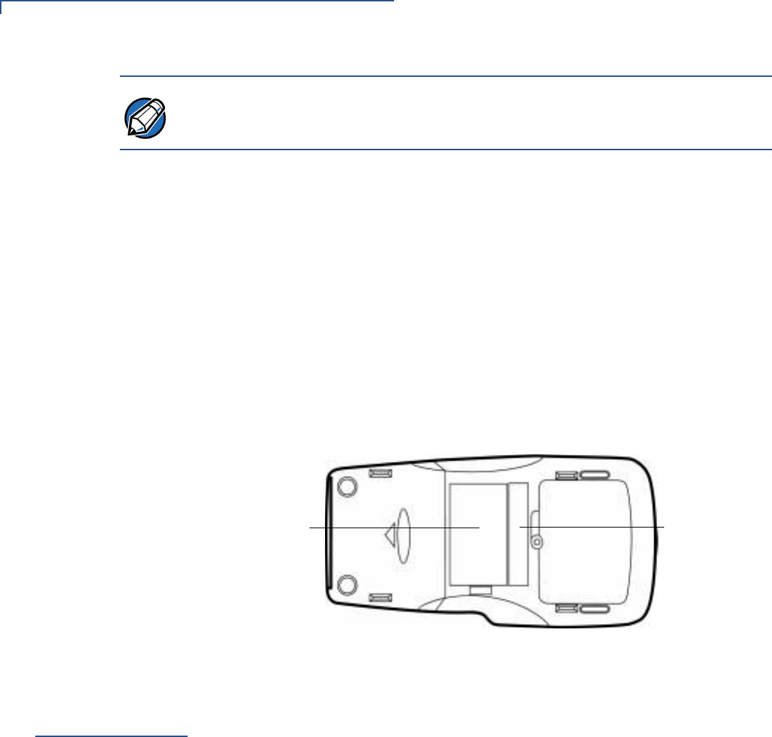
To change or install SAMs
1Remove the power cord from the back of the terminal.
2Place the terminal upside-down on a soft, clean surface to protect the lens
from scratches.
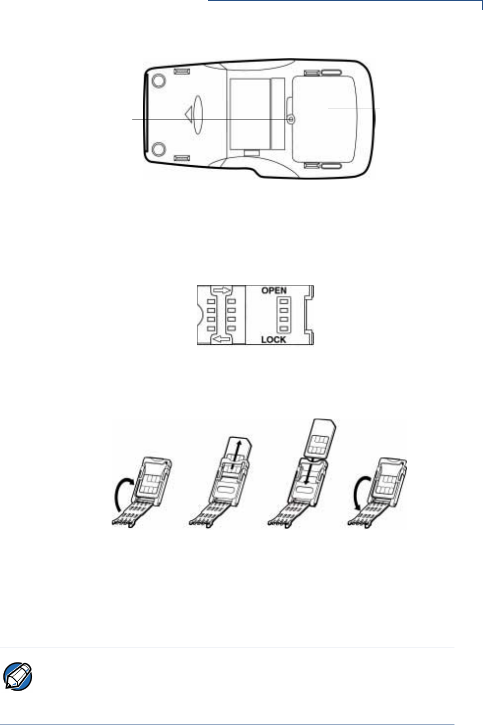
3Remove the locking screw and remove the MSAM compartment door
(see Figure 9).
NOTE To prevent damage to the print roller on the paper roll cover, always close the
cover by gently pressing down on the paper roll cover.
CAUTION Observe standard precautions for handling electrostatically sensitive devices.
Electrostatic discharges can damage this equipment. VeriFone recommends using
a grounded anti-static wrist strap.
TERMINAL SETUP
Install/Replace MSAM Cards
OMNI 37XX INSTALLATION GUIDE 17
Figure 9 MSAM Compartment Door and Locking Screw
4The MSAM cardholders are now accessible. Each cardholder consists of a
hinged tilt-up cover attached to a connector base.
5To unlock a cardholder, slide its locking plate to the unlocked position, shown
by the OPEN arrow (see Figure 10).
Figure 10 MSAM Cardholder Close-Up
6Open the cardholder by pivoting the cover on its hinges away from its
connector base (see Figure 11).
Figure 11 Using an MSAM Cardholder
7Remove any previously-installed MSAM card by sliding the card from the
cover.
8Install an MSAM card by aligning the card and carefully sliding it within the
guides on the cover until it is fully inserted.
MSAM
LOCKING SCREW COMPARTMENT
DOOR
OPENING THE REMOVING A INSTALLING A CLOSING THE
CARDHOLDER SAM CARD SAM CARD CARDHOLDER
NOTE Before inserting the MSAM card, position it as shown in Figure 11, with the card’s
gold contacts facing the smart car reader end of the terminal. The cardholder
connector base has a set of contacts and a notch post on one corner to ensure the
MSAM card is positioned correctly when the cover is closed. The MSAM card has
a notch on one corner to ensure that it fits into the connector base in only one way.

TERMINAL SETUP
Connect Optional Device(s)
18 OMNI 37XX INSTALLATION GUIDE
9Close the cardholder by pivoting the cover back to its connector base
(see Figure 11).
10 Lock each MSAM cardholder by sliding its locking plate, as shown by the
LOCK arrow, until the plate stops (see Figure 10).
11 Replace the MSAM compartment door and reinstall the locking screw
(see Figure 9).
Connect
Optional
Device(s)
The Omni 37xx supports some peripheral devices designed for use with electronic
point-of-sale terminals.
Use the two ports on the back panel to connect up to two optional devices.
The following sections discuss the most common optional devices supported by
this terminal.
Other optional devices may be supported. For more information, please contact
your VeriFone distributor.
Connect PIN Pad,
Smart Card
Reader, or Bar
Code Wand
To Connect PIN Pad, Smart Card Reader, or Bar Code Wand
1If necessary, insert the small modular plug on one end of the PIN pad cable
into the PIN pad’s modular jack.
For a bar code wand, insert the RJ45-type cable into the PIN pad serial port
on the back panel.
2If installing a PINPad 101, PINpad 201 or PINpad 1000, position and insert the
grommet to secure the cable connection.
CAUTION Before connecting any peripheral device, remove the power cord from the back of
the terminal and be sure the LED is not lit. Reconnect the power cord only after
you are finished connecting the peripheral device(s). For complete information
about peripheral installation and use, refer to the user documentation supplied with
those devices.
Table 2 Optional Devices Supported
Optional Device Connection Port
Barcode PIN Pad
CR 600 RS232
Console PIN Pad
External LAN RS232
PIN Pad PIN Pad
RS232 Electronic Cash Register RS232
NOTE RS232-type devices do not work with the PIN Pad port; PIN Pad-type devices do
not work with the RS232 port. If an optional peripheral device does not function
correctly, check the port connection.
TERMINAL SETUP
Connect Optional Device(s)
OMNI 37XX INSTALLATION GUIDE 19
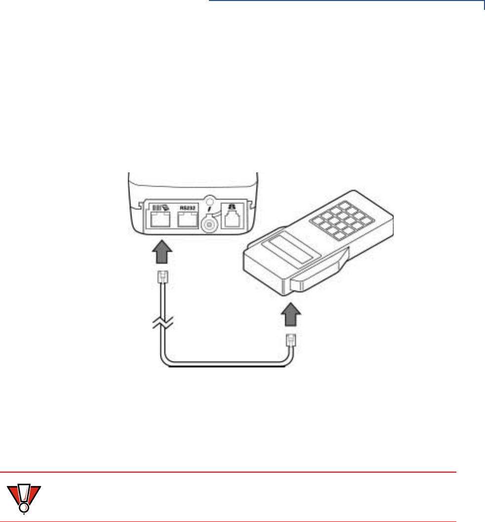
If a cable is not already connected to the smart card reader or PINpad 501,
insert the small modular plug on one end of the interface cable into the
optional device’s modular jack.
3Insert the larger RJ45-type connector on the other end of the PIN pad cable
into the PIN pad serial port on the terminal’s back panel.
Figure 12 provides an example of a Smart Card Reader connection to a Bar
code and PIN pad serial port.
Figure 12 Smart Card Reader Connection
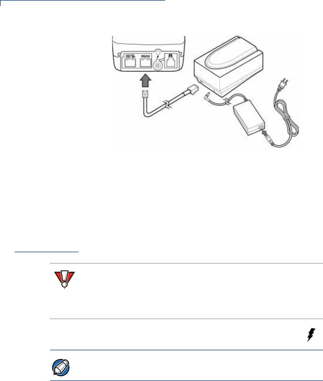
Connect Check
Reader The Omni 37xx base supports two VeriFone check readers: CR 600 and
CR 1000i. Contact your VeriFone representative or visit the online store at
www.verifone.com for information on these devices. Figure 13 provides an
example of a peripheral connection to an RS232 port.
CAUTION Check readers require a separate power source. Before connecting a check
reader or similar device, remove the power cord from the back of the terminal and
be sure the LED is not lit.
TERMINAL SETUP
Connect Terminal Power Pack
20 OMNI 37XX INSTALLATION GUIDE
Figure 13 CR 600 Check Reader Connection
External Printers
Supported Although most Omni 37xx variants have an internal thermal printer, it may be
convenient to print larger print runs (for example, daily or weekly reports) to an
external printer. The Omni 37xx base supports three VeriFone external printers:
P250, P350, and P900. Contact your VeriFone representative or visit the online
store at www.verifone.com for information on these devices. External printer
connections are through the same port as check readers (see Figure 13).
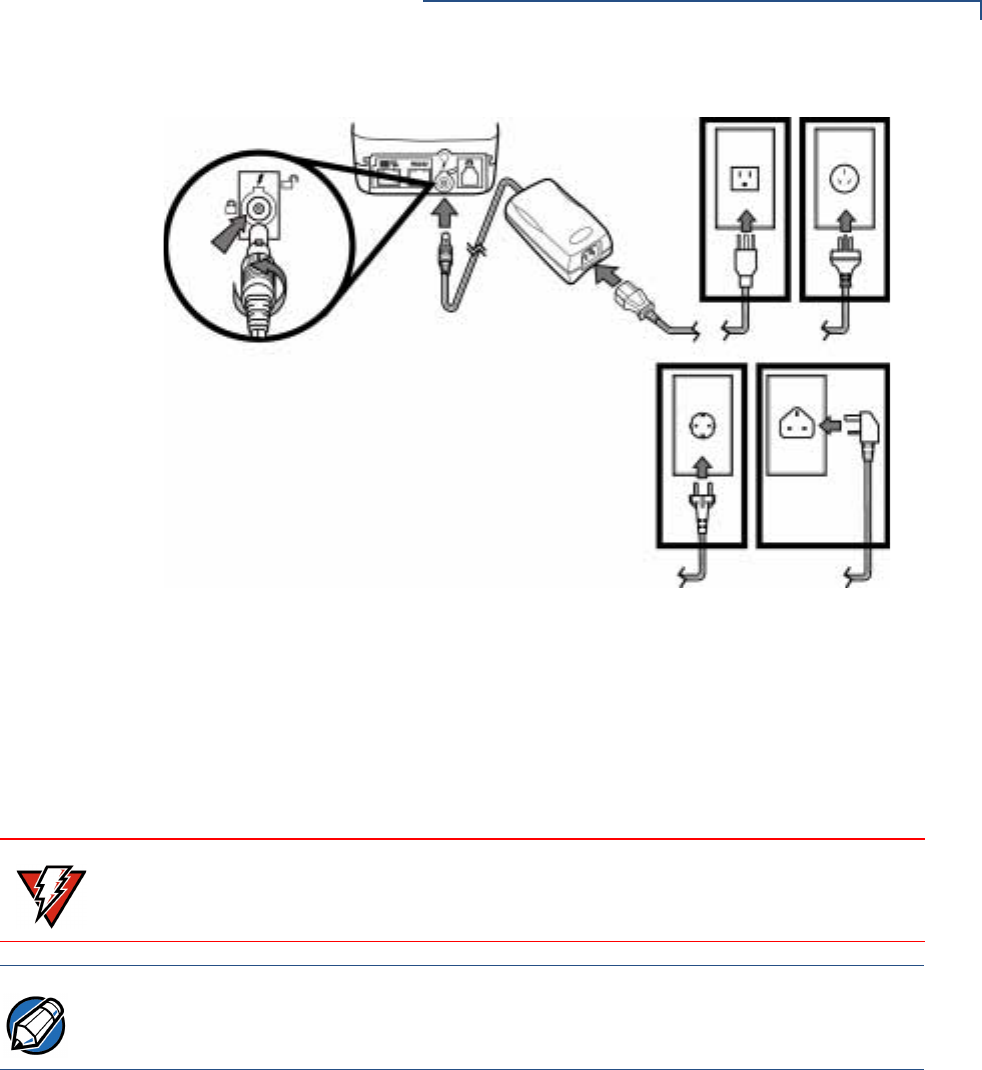
Connect
Terminal Power
Pack
When you have finished connecting any optional peripheral(s), you are ready to
connect the Omni 37xx to a power source:
1Insert the round barrel connector (see Figure 14) into the power port,
identified by the icon at right.
CAUTION Using an incorrectly rated power supply may damage the terminal or cause it not
to work as specified. Before connecting check to ensure that the power supply
being used to power the terminal matches the requirements specified at the back
of the terminal. (see Chapter 3, Specifications, for detailed power supply
specifications). Obtain the appropriately rated power supply before continuing with
troubleshooting.
NOTE The round barrel connector on the power pack cable has a plastic lock tab that
secures the power cable to the terminal.
TERMINAL SETUP
Connect Terminal Power Pack
OMNI 37XX INSTALLATION GUIDE 21
Figure 14 Omni 37xx Power Pack Connection
•To lock the connector into the power port, align the plastic lock tab so it
points up. Insert the connector, then twist it to the left.
•To unlock the connector, twist it to the right.
2Insert the power cable into the power pack.
3Plug the power pack cable into a wall outlet or surge protector.
When the terminal has power, the LCD screen lights and the green LED indicator
flashes on and off if the printer has no paper, or stays lit if paper is loaded.
If an application is loaded in the terminal, it starts after the initial VeriFone
copyright screen and displays a unique copyright screen. If no application is
loaded in the terminal, DOWNLOAD NEEDED appears on screen after the initial
VeriFone copyright screen.
WARNING Do not plug the power pack into an outdoor outlet or operate the terminal
outdoors. Also, disconnecting power during a transaction may cause transaction
data files that are not yet stored in terminal memory to be lost.
NOTE To protect against possible damage caused by lightning strikes and electrical
surges, consider installing a power surge protector.
TERMINAL SETUP
Routing The Cables Using Wire Clips
22 OMNI 37XX INSTALLATION GUIDE
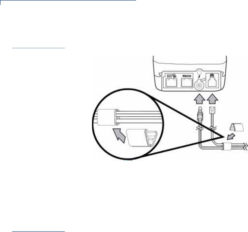
Routing The
Cables Using
Wire Clips
Since the Omni 37xx terminal is a hand-over solution, make sure the cables are
routed loosely. Use the two wire clips provided with each terminal to organize
loose cables. See Figure 15.
Figure 15 Routing Cables Using Cable Wires
1Place the telephone cord and power cable into the grooves inside the wire
clip.
2Close the wire clip and press the halves together until the it snaps closed.
3Unsnap the wire clip, to reposition as necessary.
Smart Card
Transaction
The smart card transaction procedure may vary from one application to an
another. Verify with your application provider before you perform a smart card
transaction.
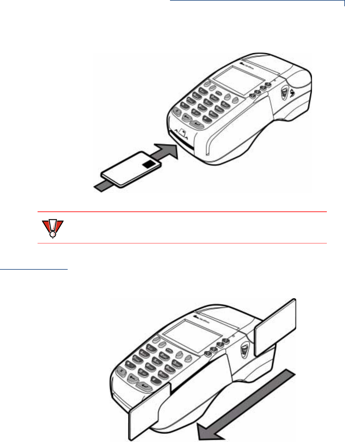
To Conduct a Smart Card Transaction
1Position a smart card with the contacts facing upward (see Figure 16).
2Insert it into the smart card reader slot in a smooth, continuous motion until it
seats firmly.
TERMINAL SETUP
Magnetic Card Reader Use
OMNI 37XX INSTALLATION GUIDE 23
3When the LCD screen indicates the transaction is completed, remove the
card.
Figure 16 Inserting the Smart Card
Magnetic Card
Reader Use
To Conduct a Credit/Debit Card Transaction
1Position a magnetic card with the stripe facing down and inward, toward the
keypad.
2Swipe it through the magnetic card reader (see Figure 17).
Figure 17 Using the Magnetic Card Reader
CAUTION Leave the smart card in the card reader until the transaction is completed.
Premature removal invalidates the transaction.

TERMINAL SETUP
Magnetic Card Reader Use
24 OMNI 37XX INSTALLATION GUIDE

OMNI 37XX INSTALLATION GUIDE 25
CHAPTER 3
Specifications
This chapter discusses power requirements, dimensions and other specifications
of the Omni 37xx terminal.
Power
Omni 37xx terminal: 24 V DC; 1.5 A
DC Power Pack For Non-switching Power Supplies:
•UL, ITE Listed, Class 2 Power Supply
•Input rated: 110 - 127V ac, 60 Hz.
•Output rated: 24V dc 1.5 A
For switching Power Supplies:
•UL, ITE Listed, Class 2, Switching Power Supply
•Input rated: 100 - 240 V ac, 50/60 Hz.
•Output rated: 24 V dc, 1.5 A
Barrel Connector Polarity:
Temperature •Operating temperature: 0° to 40° C (32° to 104° F)
•Storage temperature: -18° to + 66° C (0° to 150° F)
•Relative humidity: 15% to 90%; no condensation
External
Dimensions •Length: 210 mm (8.3 in)
•Width: 104 mm (4.1 in)
•Depth: 83 mm (3.3 in)
•Weight: 760 gms (1.675 lb)
Weight Terminal unit weight: 1.28 kg (2.82 lb)
Shipping weight: 3.26 kg (7.19 lb)
The shipping weight includes: shipping carton, terminal, power pack and cable,
telephone line cable, one Omni 37xx Certifications and Regulations, and one
Omni 37xx Quick Installation Guide.

SPECIFICATIONS
26 OMNI 37XX INSTALLATION GUIDE

OMNI 37XX INSTALLATION GUIDE 27
CHAPTER 4
Maintenance
The Omni 37xx has no user-maintainable parts.
Cleaning the
Terminal
To clean the terminal, use a clean cloth slightly dampened with water and a drop
or two of mild soap. For stubborn stains, use alcohol or an alcohol-based cleaner.
For best results, use a Verifone Cleaning Kit (refer to the Accessories and
Documentation section).
Smart Card
Reader
Do not attempt to clean the smart card reader. Doing so may void any warranty.
For smart card reader service, contact your VeriFone distributor or service
provider.
CAUTION Never use thinner, trichloroethylene, or ketone-based solvents – they may
deteriorate plastic or rubber parts.
Do not spray cleaners or other solutions directly onto the keypad or LCD screen.

MAINTENANCE
Smart Card Reader
28 OMNI 37XX INSTALLATION GUIDE

OMNI 37XX INSTALLATION GUIDE 29
CHAPTER 5
VeriFone Service and Support
For Omni 37xx terminal problems, contact your local VeriFone representative or
service provider.
For Omni 37xx product service and repair information:
•USA – VeriFone Service and Support Group, 1-800-834-9133,
Monday - Friday, 8 A.M. - 7 P.M., EST
•International – Contact your VeriFone representative
Returning a
Terminal for
Service
Before returning the Omni 37xx terminal to VeriFone, you must obtain a
Merchandise Return Authorization (MRA) number. The following procedure
describes how to return one or more Omni 37xx terminals for repair or
replacement (U.S. customers only):
1Gather the following information from the printed labels (see Figure 18) on the
bottom of each Omni 37xx terminal to be returned:
•Product ID, including the model and part number. For example,
“OMNI 3700” and “PTID xxxxxxxx”
•Serial number (S/N xxx-xxx-xxx)
2Within the United States, call VeriFone toll-free at 1-800-834-9133.
3Select the MRA option from the automated message. The MRA department is
open Monday–Friday, 8 A.M.–7 P.M., EST.
4Give the MRA representative the information gathered in Step 1.
If the list of serial numbers is long, you can fax the list, along with the
information gathered in Step 1, to the MRA department at 502-329-5947
(U.S.)
•Please address the fax clearly to the attention of the “VeriFone MRA
Dept.”
•Include a telephone number where you can be reached and your fax
number.
•You will be issued MRA number(s) and the fax will be returned to you.
NOTE International customers, please contact your local VeriFone representative for
assistance with your service, return, or replacement.
VERIFONE SERVICE AND SUPPORT
Accessories and Documentation
30 OMNI 37XX INSTALLATION GUIDE
5Describe the problem(s) and provide the shipping address where the repaired
or replacement unit must be returned.
6Keep a record of the following items:
•Assigned MRA number(s).
•VeriFone serial number assigned to the Omni 37xx terminal you are
returning for service or repair (terminal serial numbers are located on the
bottom of the unit (see Figure 18).
•Shipping documentation, such as air bill numbers used to trace the
shipment.
•Model(s) returned (model numbers are located on the VeriFone label on
the bottom of the Omni 37xx terminal).
Figure 18 Information Label on Terminal Bottom
Accessories
and
Documentation
VeriFone produces the following accessories and documentation for the Omni
37xx terminal, as listed below. When ordering, please refer to the part number in
the left column.
VeriFone Online Store at www.store.verifone.com
•USA – VeriFone Customer Development Center, 800-233-0522,
Monday - Friday, 7 A.M. - 5 P.M., MST
•International – Contact your VeriFone representative
Download Cables 05651-xx MOD10-MOD10 (terminal-to-terminal)
26263-xx 02xxx MOD10-PC DB25F (terminal-to-PC)
26264-xx 02xxx MOD10-PC DB9F (terminal-to-PC)
Cables for
Optional
Peripherals
07041-xx MOD10-MDIN9 (CR 600/CR 1000i check readers;
P250/P355/P900 external printers)
07042-xx MOD10-4P4C (all VeriFone PIN pads)
NOTE One MRA number must be issued for each Learning Products Template Version
2.1 terminal you return to VeriFone, even if you are returning several of the same
model.
SERIAL NUMBER
MODEL NUMBER

VERIFONE SERVICE AND SUPPORT
Accessories and Documentation
OMNI 37XX INSTALLATION GUIDE 31
Telephone Line
Cord 00124-17 2.1-meter (7-foot) telephone line cord, black color, with
modular RJ11-type connectors
Power Pack Contact your local VeriFone distributor to determine which power pack or
power cord fits your needs.
CPS05791-3A DC power pack (universal)
21973-01 Power cable (US)
Wire clip 07826, Rev A Wire clip
Thermal Printer
Paper CRM0039 High-grade thermal printer paper, 58-mm (2.25-inch) width,
25-meter (82-feet) length; single roll
CRM0039-01 CRM0039 in 30-roll bulk package
CRM0040 High-grade thermal printer paper, 58-mm (2.25-inch) width,
33-meter (108.26-feet) length; single roll
Paper Roll Spindle 02117-03 Plastic spindle for 58-mm (2.25-inch) rolls of thermal printer
paper; orange color
VeriFone Cleaning
Kit 02746-01 Cleaning Kit
Documentation 22398, Rev. C Omni 3750 Quick Installation Guide
22429, Rev. B Omni 37xx Certifications and Regulations
22380, Rev. E Verix Programmer’s Manual

VERIFONE SERVICE AND SUPPORT
Accessories and Documentation
32 OMNI 37XX INSTALLATION GUIDE

OMNI 37XX INSTALLATION GUIDE 33
CHAPTER 6
Troubleshooting
Guidelines
The troubleshooting guidelines provided in the following section are included to
assist you in successfully installing and configuring your Omni 37xx terminal. If
you have problems operating your Omni 37xx terminal, please read through these
troubleshooting examples.
If the problem persists even after performing the guidelines outlined, or if the
problem is not described below, contact your local VeriFone representative for
assistance. Typical examples of malfunction you may encounter while operating
your Omni 37xx terminal and steps you can take to resolve them are listed.
Blank Display When the Omni 37xx terminal LCD screen does not show correct or clear
readable information:
•Check all terminal power connections.
•Check all cable connections and verify that the telephone line is properly
connected.
•If the problem persists, contact your local VeriFone service provider for
assistance.
Terminal Does
Not Dial Out
If the terminal does not dial out:
•Check the telephone line connections.
•Check to make sure the telephone line is working by plugging it into a working
telephone and listening for a dial tone.
NOTE The Omni 37xx terminal comes equipped with tamper-evident labels. The Omni
37xx contains no user serviceable parts. Do not, under any circumstance, attempt
to disassemble the terminal. Perform only those adjustments or repairs specified
in this installation guide. For all other services, contact your local VeriFone service
provider. Service conducted by parties other than authorized VeriFone
representatives may void any warranty.
CAUTION Using an incorrectly rated power supply may damage the terminal or cause it not
to work as specified. Before troubleshooting, check to ensure that the power
supply being used to power the terminal matches the requirements specified at
the back of the terminal. (See Chapter 3, Specifications, for detailed power supply
specifications). Obtain the appropriately rated power supply before continuing with
troubleshooting.

TROUBLESHOOTING GUIDELINES
Printer Does Not Print
34 OMNI 37XX INSTALLATION GUIDE
•Replace the telephone cable that connects the terminal with a cable you know
is working correctly.
•If the problem persists, contact your local VeriFone service provider for
assistance.
Printer Does
Not Print
If the printer does not work properly:
•Check all terminal power connections. The internal thermal printer receives
power directly from the Omni 37xx terminal. The green power-on indicator
light must be ON.
•Check to make sure the paper roll cover is properly latched.
•If the green power-on indicator is blinking on and off, the printer is out of paper.
Open the paper roll cover and install a new roll of printer paper, as described
in Install Paper Roll.
•If the problem persists, contact your VeriFone distributor or service provider.
Printer Paper
Jam
If paper jams up inside the printer:
•Press the button on the side of the terminal to unlatch the paper roll cover,
then open the cover.
•Remove the damaged paper from the paper roll and clear the feed
mechanism.
•Re-install the roll of printer paper, as described in Install Paper Roll.
•If the problem persists, it may be due to poor paper quality. Install a new
roll of higher-quality paper.
See To Install a Paper Roll.
Peripherals
Device Does
Not Work
If any of the peripheral device (PIN Pad, Smart Card Reader, or Bar Code Wand)
does not work properly:
•Check the power cable connection to the peripheral device.
•Check that the device connected to the serial port has power and is
functioning properly. If possible, perform a self-test on the device in question.
•The cable connecting the optional device to the Omni 37xx terminal serial port
may be defective. Try a different serial cable.
•If the problem persists, contact your local VeriFone representative for
assistance.
See Connect Optional Device(s).
WARNING Poor-quality paper may jam the printer. For high-quality VeriFone paper, refer to
the Accessories and Documentation section.

TROUBLESHOOTING GUIDELINES
Keypad Does Not Respond
OMNI 37XX INSTALLATION GUIDE 35
Keypad Does
Not Respond
If the keypad does not respond properly:
•Check the LCD screen. If it displays the wrong character or nothing at all when
you press a key, follow the steps outlined in Transactions Fail To Process.
•If pressing a function key does not perform the expected action, refer to the
user documentation for that application to ensure you are entering data
correctly.
•If the problem persists, contact your local VeriFone representative for
assistance.
Transactions
Fail To Process
There are several possible reasons why the terminal may not be processing
transactions. Use the following steps to check troubleshoot failures.
Check Magnetic Card Reader
•Perform a test transaction using one or more different magnetic stripe cards to
ensure the problem is not a defective card.
•Ensure that you are swiping cards properly. With the Omni 37xx card reader,
the black, magnetic stripe on the card should face inward, toward the keypad.
•Process a transaction manually using the keypad instead of the card reader. If
the manual transaction works, the problem may be a defective card reader.
Contact your VeriFone distributor or service provider. If the manual transaction
does not work, proceed to Check Telephone Line.
Check Smart Card Reader
•Perform a test transaction using several different smart cards to ensure the
problem is not a defective card.
•Ensure that the card is inserted correctly.
•Ensure the MSAM cards are properly inserted in the cardholders and the
cardholders are properly secured (see Install/Replace MSAM Cards).
•Process the transaction manually using the keypad instead of the card reader.
If the manual transaction processes, the problem may be a defective card
reader. Contact your VeriFone distributor or service provider. If the manual
transaction does not process, proceed to Check Telephone Line.
Check Telephone Line
•Disconnect the telephone line from the back of the Omni 37xx terminal and
connect it to a working telephone to check for a dial tone. If there is no dial
tone, replace the telephone cable.
•If the problem appears to be with the telephone line, check with the party you
are trying to call to see if their system is operational. If they are not
experiencing difficulties with their line, contact the telephone company and
have your line checked. If the telephone line works, contact your local
VeriFone representative for assistance.

TROUBLESHOOTING GUIDELINES
Transactions Fail To Process
36 OMNI 37XX INSTALLATION GUIDE

OMNI 37XX INSTALLATION GUIDE 37
INDEX
A
accessories 30
cables for optional peripherals 30
documentation 31
download cables 30
ordering 31
paper roll spindle 31
power packs 31
telephone line cord 31
thermal printer paper 31
VeriFone cleaning kit 31
B
bar code wand
connect 18
C
cables
ordering cables for optional peripherals 30
ordering download cables 30
check readers 19
connect
bar code wand 18
connection ports 12
communications port 12
RJ45-type modular jacks 13
bar code 13
PIN Pad 13
RS232 13
D
direct telephone line connection 13
display
troubleshooting 33
documentation 30
documentation, ordering 31
download cables, ordering 30
E
electrostatic discharge 16
I
installation 7
connecting a PINpad 18
connecting a smart card reader/writer 18
connecting optional device(s) 18
connecting the terminal power pack 20
connecting the terminal to a telephone line 13
MSAM cardholders 16
MSAM cards 16
peripherals 19
setting up a direct telephone line connection 13
table of peripheral devices 18
terminal location 9
unpack the shipping carton 10
using the magnetic card reader 23
K
keypad
troubleshooting 35
M
magnetic card reader,using 23
maintenance
cleaning the terminal 27
returning a terminal for repair or replacement 29
MSAM cardholders 16
MSAM cards 16
O
optional devices, connecting 18
P
paper rolls
for thermal printer 14, 34
peripherals
cables 30
check readers 19
installation 19
PINpad 18
printers 19
smart card reader/writers 18

INDEX
38 OMNI 37XX INSTALLATION GUIDE
table of supported devices 18
PINpad
connecting 18
power pack
AC version 31
connecting 20
DC version 31
ordering 31
printer
paper roll spindle 31
troubleshooting 34
printer paper
ordering 31
S
service
returning a terminal for repair or replacement 29
smart card reader/writer
connecting 18
T
telephone line connections 13
direct 13
telephone line cord, ordering 31
terminal
accessories 30
cleaning 27
documentation 30
repair 29
replacement 29
service and support 29
troubleshooting 33
terminal features
general 11
thermal printer
about thermal printer paper 14, 34
troubleshooting 34
troubleshooting
display 33
guidelines 33
keypad 35
printer 34
terminal transactions 35

Omni 37xx
Installation Guide
VeriFone Part Number 22399, Revision B
VERIX
OPERATING
ENVIRONMENT
SOFTPAY
E-PAYMENT
APPLICATION
VERIX
DEVELOPMENT
TOOLS
DEVELOPER
TOOLKIT
VERISHIELD
SECURITY
ARCHITECTURE
OMNI 37XX
HAND-OVER-COUNTER
MULTI-APPLICATION
APPLIANCES
OMNI 33XX
MULTI-APPLICATION
APPLIANCES
VERICENTRE
APPLIANCE
MANAGEMENT
SUITE
VERIX
MANAGEMENT
MULTI-APP
CONDUCTOR
SYSTEM
MULITPLE APPLICATION
VeriFone, Inc.
2455 Augustine Drive
Santa Clara CA 95054-3002
Tel: 408-330-6300
Fax: 408-330-6406
www.verifone.com
Omni 37XX Installation Guide (VeriFone Part Number 22399)
Appendix - (Some Wireless Models )
■ Install/Replace SIM Card (GSM models)
The SIM (Subscriber Identity Module) card is a smart card inserted in the Omni 3750 GSM
terminal that contains your GSM radio account information. Use the following procedure to
replace or install a SIM card.
1. Remove screw from SIM card access door on back of Omni 3750 terminal (Fig 1).
2. Remove the SIM card access door.
3. Open the SIM cardholder and slide the SIM card supplied by your provider into the
cardholder.
Fig. 1

NOTE: Do not lose the SIM card dust cover or retaining screw.
NOTE: The SIM cardholder has a notch on one corner to ensure the SIM card is positioned
correctly. The SIM card has a notch on one corner for easy orientation in the cardholder. When
inserting the SIM card, position it with the card’s gold contacts facing down.
4. Replace the SIM card access door and screw.
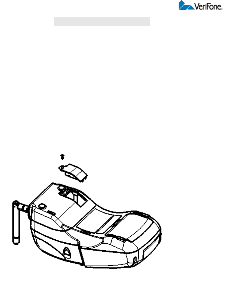
■ Antenna
For some Omni 3750 terminals to establish a wireless connection, and external antenna is
provided. This connection allows communication with your service provider to upload
transaction data from the terminal and download system upgrade to the terminal. Radio service is
activated by your service provider.
NOTE: Only use the antenna designed for your unit. Failure to use the proper antenna results in
the inability to establish a wireless connection.
Caution : Never hold the unit by the antenna; doing so may break the connection and void your
warranty.
Installation: The Omni 3750 should arrive from manufacture with the antenna attached. If
unattached, use the following procedure to install the antenna :
1. Locate the antenna port on the back of the Omni 3750 terminal (Fig. 2).
2. Align the respective “notch” inside the antenna to the key in the terminal
3. Push gently on the center of the base of the antenna until it locks in position.
Orientation : To establish good wireless communication (uplink), it is important that the antenna
always be vertically aligned with respect to ground and sky.
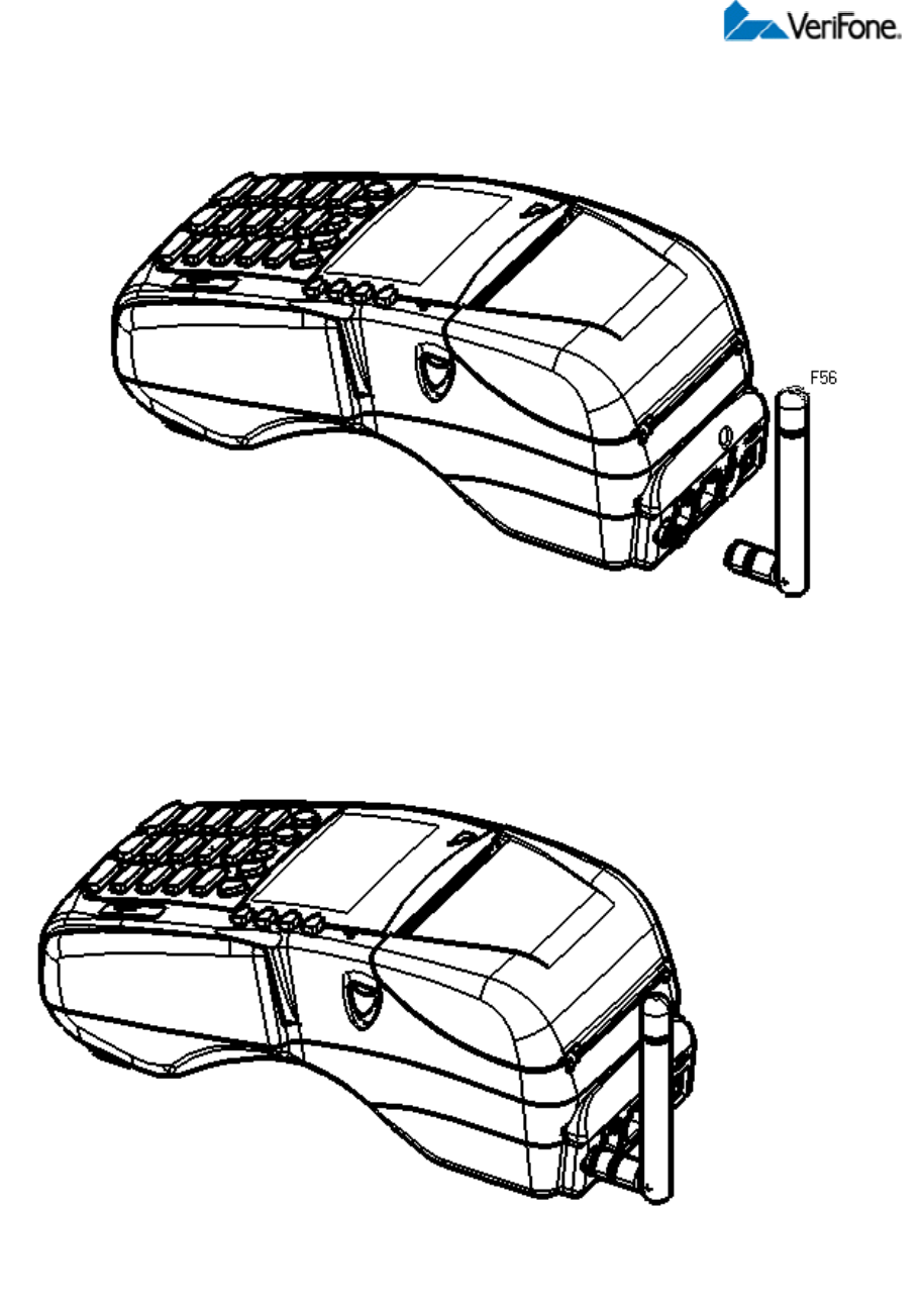
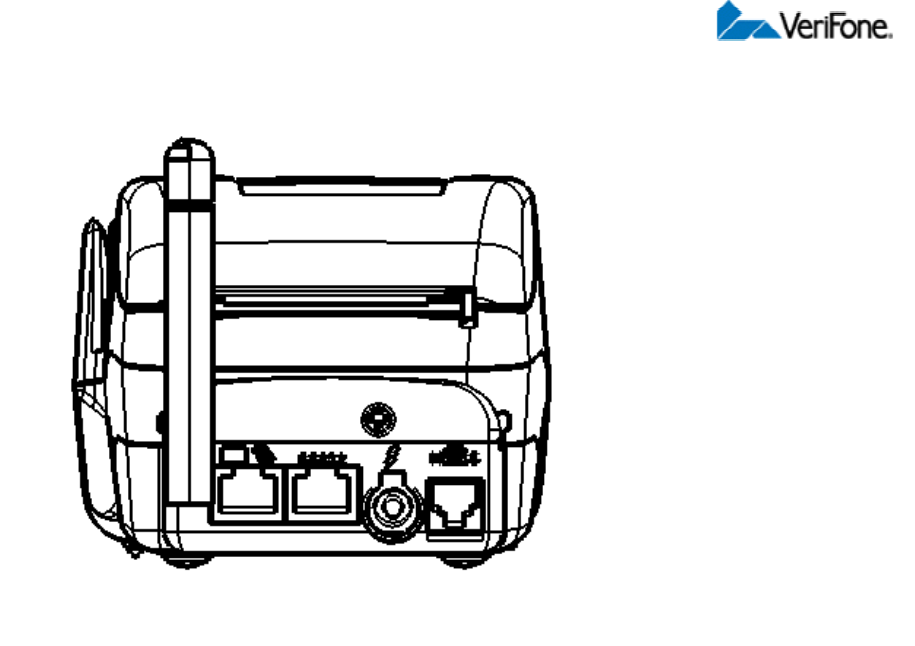
Fig. 2

Note:
FEDERAL COMMUNICATIONS COMMISSION
This device complies with Part 15 of the FCC Rules. Operation is subject to the
following two conditions:(1) this device may not cause harmful interference,
and (2) this device must accept any interference received, including
interference that may cause undesired operation.
This equipment has been tested and found to comply with the limits for a Class
B digital device, pursuant to Part 15 of the FCC Rules. These limits are
designed to provide reasonable protection against harmful interference in a
residential installation. This equipment generates, uses and can radiated radio
frequency energy and, if not installed and used in accordance with the
instructions, may cause harmful interference to radio communications.
However, there is no guarantee that interference will not occur in a particular
installation If this equipment does cause harmful interference to radio or
television reception, which can be determined by turning the equipment off and
on, the user is encouraged to try to correct the interference by one or more of
the following measures:
-Reorient or relocate the receiving antenna.
-Increase the separation between the equipment and receiver.
-Connect the equipment into an outlet on a circuit different from that to which
the receiver is connected.
Changes or modifications not expressly approved by the party responsible for
compliance could void the user‘s authority to operate the equipment.
The antenna(s) used for this transmitter must not be co-located or operating in
conjunction with any other antenna or transmitter.
This equipment complies with FCC radiation exposure limits set forth for an
uncontrolled environment. In order to avoid the possibility of exceeding the
FCC radio frequency exposure limits, human proximity to the antenna shall not
be less than 20cm (8 inches) during normal operation.