Contents
User Manual

Verifone Part Number DOCxxx-xxx-EN-A, Revision A.3
V200 Non-Touch
Installation Guide
All rights reserved. No part of the contents of this document may be reproduced or transmitted in any form without the written
permission of Verifone, Inc.
The information contained in this document is subject to change without notice. Although Verifone has attempted to ensure the
accuracy of the contents of this document, this document may include errors or omissions. The examples and sample programs are
for illustration only and may not be suited for your purpose. You should verify the applicability of any example or sample program
before placing the software into productive use. This document, including without limitation the examples and software programs, is
supplied “As-Is.”
Verifone, Inc.
1-800-Verifone
www.verifone.com
Verifone Part Number DOCxxx-xxx-EN-A, Revision A.3
V200 Non-Touch Installation Guide
© 2015 Verifone, Inc.
Verifone and the Verifone logo are registered trademarks of Verifone. Other brand names or trademarks associated with Verifone’s
products and services are trademarks of Verifone, Inc.
All other brand names and trademarks appearing in this manual are the property of their respective holders.
Comments? Please e-mail all comments on this document to your local Verifone Support Team.

V200 NON-TOUCH INSTALLATION GUIDE 3
CONTENTS
PREFACE . . . . . . . . . . . . . . . . . . . . . . . . . . . . . . . . . . . . . . . 5
Audience. . . . . . . . . . . . . . . . . . . . . . . . . . . . . . . . . . . . . . . . . . . . . . . . . . . . . . . . 5
Organization . . . . . . . . . . . . . . . . . . . . . . . . . . . . . . . . . . . . . . . . . . . . . . . . . . . . . 5
Related Documentation . . . . . . . . . . . . . . . . . . . . . . . . . . . . . . . . . . . . . . . . . . . . 5
Conventions and Acronyms . . . . . . . . . . . . . . . . . . . . . . . . . . . . . . . . . . . . . . . . . 5
Document Conventions. . . . . . . . . . . . . . . . . . . . . . . . . . . . . . . . . . . . . . . . . . 6
Acronym Definitions . . . . . . . . . . . . . . . . . . . . . . . . . . . . . . . . . . . . . . . . . . . . 6
CHAPTER 1
Device Overview Features and Benefits . . . . . . . . . . . . . . . . . . . . . . . . . . . . . . . . . . . . . . . . . . . . . 9
Connectivity . . . . . . . . . . . . . . . . . . . . . . . . . . . . . . . . . . . . . . . . . . . . . . . . . . 9
Performance . . . . . . . . . . . . . . . . . . . . . . . . . . . . . . . . . . . . . . . . . . . . . . . . . . 9
Security. . . . . . . . . . . . . . . . . . . . . . . . . . . . . . . . . . . . . . . . . . . . . . . . . . . . . . 9
Form Factor . . . . . . . . . . . . . . . . . . . . . . . . . . . . . . . . . . . . . . . . . . . . . . . . . 10
Exceptional Ease of Use. . . . . . . . . . . . . . . . . . . . . . . . . . . . . . . . . . . . . . . . 10
Countertop Performance in a Hand-Over Design. . . . . . . . . . . . . . . . . . . . . 10
True Multi-Application Capability . . . . . . . . . . . . . . . . . . . . . . . . . . . . . . . . . 10
CHAPTER 2
Setup Selecting Unit Location. . . . . . . . . . . . . . . . . . . . . . . . . . . . . . . . . . . . . . . . . . . . 13
Ease of Use . . . . . . . . . . . . . . . . . . . . . . . . . . . . . . . . . . . . . . . . . . . . . . . . . 13
Environmental Factors . . . . . . . . . . . . . . . . . . . . . . . . . . . . . . . . . . . . . . . . . 13
Electrical Considerations . . . . . . . . . . . . . . . . . . . . . . . . . . . . . . . . . . . . . . . 14
Ensuring User Privacy . . . . . . . . . . . . . . . . . . . . . . . . . . . . . . . . . . . . . . . . . 14
PIN Protection Measures . . . . . . . . . . . . . . . . . . . . . . . . . . . . . . . . . . . . . . . 15
Privacy Shield . . . . . . . . . . . . . . . . . . . . . . . . . . . . . . . . . . . . . . . . . . . . . . . . 16
Unpacking the Shipping Carton . . . . . . . . . . . . . . . . . . . . . . . . . . . . . . . . . . . . . 16
Examining the Unit’s Features . . . . . . . . . . . . . . . . . . . . . . . . . . . . . . . . . . . . . . 17
Front Panel . . . . . . . . . . . . . . . . . . . . . . . . . . . . . . . . . . . . . . . . . . . . . . . . . . 17
Connection Ports . . . . . . . . . . . . . . . . . . . . . . . . . . . . . . . . . . . . . . . . . . . . . 18
Establishing Communication . . . . . . . . . . . . . . . . . . . . . . . . . . . . . . . . . . . . . . . 20
Connecting by Telephone Line . . . . . . . . . . . . . . . . . . . . . . . . . . . . . . . . . . . 20
Connecting by Ethernet Cable . . . . . . . . . . . . . . . . . . . . . . . . . . . . . . . . . . . 20
Loading a Paper Roll in the Printer. . . . . . . . . . . . . . . . . . . . . . . . . . . . . . . . . . . 21
Installing or Replacing MSAM Cards . . . . . . . . . . . . . . . . . . . . . . . . . . . . . . . . . 23
Connecting Optional Devices . . . . . . . . . . . . . . . . . . . . . . . . . . . . . . . . . . . . . . . 24
Optional Device Connections . . . . . . . . . . . . . . . . . . . . . . . . . . . . . . . . . . . . 24
Connecting ECRs to the V200 Non-Touch . . . . . . . . . . . . . . . . . . . . . . . . . . 24
Connecting the Terminal Power Pack . . . . . . . . . . . . . . . . . . . . . . . . . . . . . . . . 25
Privacy Shield. . . . . . . . . . . . . . . . . . . . . . . . . . . . . . . . . . . . . . . . . . . . . . . . . . . 27
Using the CTLS Reader . . . . . . . . . . . . . . . . . . . . . . . . . . . . . . . . . . . . . . . . . . . 27
Using the Smart Card Reader . . . . . . . . . . . . . . . . . . . . . . . . . . . . . . . . . . . . . . 27
Using the Magnetic Card Reader . . . . . . . . . . . . . . . . . . . . . . . . . . . . . . . . . . . . 28
Periodic Inspection . . . . . . . . . . . . . . . . . . . . . . . . . . . . . . . . . . . . . . . . . . . . . . . 29

CONTENTS
4V200 NON-TOUCH INSTALLATION GUIDE
CHAPTER 3
Specifications Technical Specifications. . . . . . . . . . . . . . . . . . . . . . . . . . . . . . . . . . . . . . . . . . . 31
Unit Power Requirements. . . . . . . . . . . . . . . . . . . . . . . . . . . . . . . . . . . . . . . 31
Temperature . . . . . . . . . . . . . . . . . . . . . . . . . . . . . . . . . . . . . . . . . . . . . . . . . 31
Memory. . . . . . . . . . . . . . . . . . . . . . . . . . . . . . . . . . . . . . . . . . . . . . . . . . . . . 31
Magnetic Stripe Card . . . . . . . . . . . . . . . . . . . . . . . . . . . . . . . . . . . . . . . . . . 31
Smart Card Reader. . . . . . . . . . . . . . . . . . . . . . . . . . . . . . . . . . . . . . . . . . . . 31
SAM Requirements. . . . . . . . . . . . . . . . . . . . . . . . . . . . . . . . . . . . . . . . . . . . 31
Communication. . . . . . . . . . . . . . . . . . . . . . . . . . . . . . . . . . . . . . . . . . . . . . . 31
Display . . . . . . . . . . . . . . . . . . . . . . . . . . . . . . . . . . . . . . . . . . . . . . . . . . . . . 32
Thermal Printer . . . . . . . . . . . . . . . . . . . . . . . . . . . . . . . . . . . . . . . . . . . . . . . 32
SD Memory (Media version only) . . . . . . . . . . . . . . . . . . . . . . . . . . . . . . . . . 32
CHAPTER 4
Maintenance and
Cleaning Additional Safety Information . . . . . . . . . . . . . . . . . . . . . . . . . . . . . . . . . . . . . . . 33
Potentially Explosive Environments . . . . . . . . . . . . . . . . . . . . . . . . . . . . . . . 33
CHAPTER 5
Service and Support Service Returns . . . . . . . . . . . . . . . . . . . . . . . . . . . . . . . . . . . . . . . . . . . . . . . . . 35
Accessories and Documentation . . . . . . . . . . . . . . . . . . . . . . . . . . . . . . . . . . . . 36
Connection Cables . . . . . . . . . . . . . . . . . . . . . . . . . . . . . . . . . . . . . . . . . . . . 37
Power Cables . . . . . . . . . . . . . . . . . . . . . . . . . . . . . . . . . . . . . . . . . . . . . . . . 37
Cleaning Kit. . . . . . . . . . . . . . . . . . . . . . . . . . . . . . . . . . . . . . . . . . . . . . . . . . 37
Documentation . . . . . . . . . . . . . . . . . . . . . . . . . . . . . . . . . . . . . . . . . . . . . . . 37
CHAPTER 6
Troubleshooting
Guidelines Blank Display . . . . . . . . . . . . . . . . . . . . . . . . . . . . . . . . . . . . . . . . . . . . . . . . . . . 39
Terminal Does Not Dial Out . . . . . . . . . . . . . . . . . . . . . . . . . . . . . . . . . . . . . . . . 39
Printer Paper Jam. . . . . . . . . . . . . . . . . . . . . . . . . . . . . . . . . . . . . . . . . . . . . . . . 40
Keypad Does Not Respond . . . . . . . . . . . . . . . . . . . . . . . . . . . . . . . . . . . . . . . . 40
Peripheral Device Does Not Work . . . . . . . . . . . . . . . . . . . . . . . . . . . . . . . . . . . 40
Transactions Fail To Process. . . . . . . . . . . . . . . . . . . . . . . . . . . . . . . . . . . . . . . 40
Printer Does Not Print. . . . . . . . . . . . . . . . . . . . . . . . . . . . . . . . . . . . . . . . . . . . . 41
Terminal Display Does not Show Correct or Readable Information. . . . . . . . . . 42
CHAPTER 7
Port Pinouts RS-232 Port (COM1) . . . . . . . . . . . . . . . . . . . . . . . . . . . . . . . . . . . . . . . . . . 43
Ethernet Port
(LAN). . . . . . . . . . . . . . . . . . . . . . . . . . . . . . . . . . . . . . . . . . . . . . . . . . . . . . . 43
USB Pinout
(Host Port). . . . . . . . . . . . . . . . . . . . . . . . . . . . . . . . . . . . . . . . . . . . . . . . . . . 44
USB Pinout
(Client Port). . . . . . . . . . . . . . . . . . . . . . . . . . . . . . . . . . . . . . . . . . . . . . . . . . 44
APPENDIX A
Caution and
Warning Messages V200 Non-Touch Caution and Warning Messages . . . . . . . . . . . . . . . . . . . . . . 45

V200 NON-TOUCH INSTALLATION GUIDE 5
PREFACE
This guide is the primary source of information for setting up and installing the
V200 Non-Touch unit.
Audience
This guide describes the card reader’s features, and provides the basic
information for its installation and configuration.
Organization
This guide is organized as follows:
Chapter 1, Device Overview. Provides an overview of the device.
Chapter 2, Setup. Explains setup and installation of the device, selecting a
location, and establishing connections with other devices.
Chapter 3, Specifications. Discusses the power requirements and dimensions of
the device.
Chapter 4, Maintenance and Cleaning. Explains maintenance of the device.
Chapter 5, Service and Support. Provides information on contacting your Verifone
service provider and information on how to order accessories or documentation
from Verifone.
Chapter 6, Troubleshooting Guidelines. Provides troubleshooting guidelines
should you encounter a problem with unit installation and configuration.
Chapter 7, Port Pinouts. Shows the different pinout settings for ports on the V200
Non-Touch
Appendix A, Caution and Warning Messages. Shows the UL/cUL certification-
compliant translations of all Warning and Caution messages in this installation
guide.
Related
Documentation
To learn more about the card reader and controller device, refer to the following
set of documents and their associated Verifone Part Numbers (VPNs).
Conventions and
Acronyms
This section describes the conventions and acronyms used in this guide.
V200 Non-Touch Certifications and Regulations Sheet VPN DOCxxx-xxx-EN
V200 Non-Touch Quick Installation Guide VPN DOCxxx-xxx-EN
V200 Non-Touch Reference Guide VPN DOCxxx-xxx-EN
PREFACE
Conventions and Acronyms
6V200 NON-TOUCH INSTALLATION GUIDE
Document
Conventions
Various conventions are used to help you quickly identify special formatting.
Table 1 describes these conventions and provides examples of their use.
Acronym Definitions
Various acronyms are used in place of the full definition. Table 2 presents
acronyms and their definitions.
Table 1 Document Conventions
Convention Meaning Example
Blue Text in blue indicates terms that
are cross referenced.
See Conventions and
Acronyms.
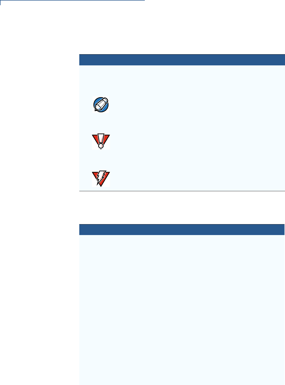
The pencil icon is used to
highlight important information.
If exchanging cables, use a
Verifone-approved cable.
The caution symbol indicates
possible hardware or software
failure, or loss of data.
Using an incorrectly rated power
supply can damage the unit or
cause it to malfunction.
The lightning symbol is used as
a warning when bodily injury
might occur.
For safety, do not string cables
or cords across a walkway.
NOTE
CAUTION
WARNING
Table 2 Acronym Definitions
Acronym Definitions
ATM Automated teller machine
COM Communications port
CTLS Contactless
DDA Dynamic Data Authentication
ECC Elliptic Curve Cryptography
EMV Europay, MasterCard, and Visa
ETH Ethernet
HSM Hardware security module
HW Hardware
I/O Input/Output
ITP Internal thermal printer
LCD Liquid crystal display
LPS Lines per second
MB Mega-bytes
MOD 10 Luhn algorithm or Luhn formula, also known as "mod 10"
MSAM Micromodule-Size Secure Access Module
MSR Magnetic-stripe card reader
PCI Payment Card Industry

PREFACE
Conventions and Acronyms
V200 NON-TOUCH INSTALLATION GUIDE 7
PED PIN-entry device
PIN Personal Identification Number
QVGA Quarter Video Graphics Array
RF Radio Frequency
RJ45 Registered Jack 45 modular connector
RS-232 Recommended Standard 232
SAM Secure Access Module
SC Smart card
SCR Smart card reader
SD Secure Digital
SDA Static Data Authentication
SDHC Secure Digital High Capacity
SIM Subscriber Identity Module
SMA SubMiniature version A connector
SRED Secure Reading and Exchange of Data
TFT Thin-film transistor
TQM Terminal Quality Management
UI User interface
USB Universal Serial Bus
VM Vending Machine
WAN Wide Area Networks
Table 2 Acronym Definitions (continued)
Acronym Definitions

PREFACE
Conventions and Acronyms
8V200 NON-TOUCH INSTALLATION GUIDE

V200 NON-TOUCH INSTALLATION GUIDE 9
CHAPTER 1
Device Overview
This chapter provides a brief description of the V200 Non-Touch terminal.
The V200 Non-Touch offers several communication options, enhanced display,
increased processing power and two USB peripheral ports.
The V200 Non-Touch terminal uses a robust, sleek, and highly functional design.
Features and
Benefits
The V200 Non-Touch is an all-in-one countertop payment system that provides
quick contactless (CTLS), magnetic-stripe card reader (MSR) and smart card
(SC) payment processing with a fast internal thermal printer (ITP) and clear color
TFT LCD display.
Connectivity
•2 SAM ports (standard size)
•MOD 10 2-in-1 I/O port
•Host USB port
•Client USB port
•Telco port (56K modem)
•Ethernet Port
Performance
•600 MHz, 32-bit processor (CPU)
•Increased memory
•V200 Non-Touch: 128MB RAM
•V200 Non-Touch Plus: 512MB RAM
•Both products use 256MB Flash
•2.8-inch QVGA LCD (240RGB x 320 dots)
•Fastest encryption/decryption appliance on the market
•Backlit keypad with tactile and audible feedback.
Security
•PCI 4.0 compliant
•Direct key injection using industry standard HSMs
•VeriShield Retain
NOTE
The connectivity ports are easily accessible from the underside of the terminal.

DEVICE OVERVIEW
Features and Benefits
10 V200 NON-TOUCH INSTALLATION GUIDE
•VeriShield Remote Key
•Verifone Secure Data
•VeriShield Total Protect
•MasterCard TQM
•IPP8 functionality plus multiple DUKPT engines
•EMV L1 and L2
•ISO7816-3, ISO7816-10 and EMV 4.3 standards
Form Factor
•The V200 Non-Touch is ergonomically designed to fit both the traditional
countertop and hand-over models.
Exceptional Ease of
Use
•Four-way navigation button with two selection keys for UI access.
•The contactless functionality offers a convenient payment option for
consumers.
•The bold design is sleek, stylish, and lightweight for conveniently handing the
terminal to the consumer for PIN entry or other input.
•An intuitive ATM-style interface, a large 8-line by 21-character backlit display
with backlit keypad, and extra-size menu prompts, simplify training and reduce
help desk calls.
•The multiple font-capable integrated thermal printer simplifies paper loading
and reduces paper jams. Uses 57 mm wide x 40 mm diameter paper rolls,
prints at 30 lines per second (LPS).
•The triple-track, high-coercivity card reader handles most magnetic stripe
cards.
Countertop
Performance in a
Hand-Over Design
•The 32-bit processing and multi-tasking capabilities ensures fast processing of
payment, payment-related, and value-added applications.
•Exceptional display and printer graphics-handling capabilities that quickly
render logos, graphical fonts, and character-based languages.
•The V200 Non-Touch ensures uncompromising reliability from Verifone, the
worldwide leader in e-payment.
True Multi-
Application
Capability
•The V200 Non-Touch offers offers 128MB and 512MB for V200 Non-Touch
Plus of random access memory, and 256MB dynamic memory allocation for
operating system, which supports multiple applications on a single terminal.
•The primary smart card reader and the MSAMs safeguard sensitive financial
data and support multiple smart card schemes.
•V200 Non-Touch units are certified for ISO7816-3, ISO7816-10 and EMV4.3
standards for smart card solutions.

DEVICE OVERVIEW
Features and Benefits
V200 NON-TOUCH INSTALLATION GUIDE 11
•The VeriShield security architecture meets published specifications for PCI
PED and provides sophisticated file authentication to prevent execution of
unauthorized software on V200 Non-Touch devices.
•Biometrics and Barcode reader support via MOD 10 connector.

DEVICE OVERVIEW
Features and Benefits
12 V200 NON-TOUCH INSTALLATION GUIDE

V200 NON-TOUCH INSTALLATION GUIDE 13
CHAPTER 2
Setup
This chapter describes the setup procedures for the V200 Non-Touch terminal,
under the following sections:
•Selecting Unit Location
•Unpacking the Shipping Carton
•Examining the Unit’s Features
•Establishing Communication
•Loading a Paper Roll in the Printer
•Installing or Replacing MSAM Cards
•Connecting Optional Devices
•Connecting the Terminal Power Pack
•Privacy Shield
•Using the CTLS Reader
•Using the Smart Card Reader
•Using the Magnetic Card Reader
Selecting Unit
Location
Use the following guidelines when selecting a location for your device.
Ease of Use
•Select a location convenient for both merchant and cardholder.
•Select a flat support surface, such as a countertop or table.
•Select a location near a power outlet and a telephone/modem line connection.
•For safety, do not string the power cord in a walkway or place it across a
walkway on the floor.
Environmental
Factors
•Do not use the terminal where there is high heat, dust, humidity, moisture, or
caustic chemicals or oils.
•Keep the terminal away from direct sunlight and anything that radiates heat,
such as a stove or motor.
SETUP
Selecting Unit Location
14 V200 NON-TOUCH INSTALLATION GUIDE
•Do not use the terminal outdoors.
Electrical
Considerations
•Avoid using this product during electrical storms.
•Do not place a CTLS device within 10 cm from metallic objects to avoid
interference to the CTLS field.
•Avoid locations near electrical appliances or other devices that cause
excessive voltage fluctuations or emit electrical noise (for example, air
conditioners, electric motors, neon signs, high-frequency or magnetic security
devices, or computer equipment).
•Do not use the terminal near water or in moist conditions.
Ensuring User
Privacy
Use the following guidelines to protect the user’s privacy when he enters his PIN:
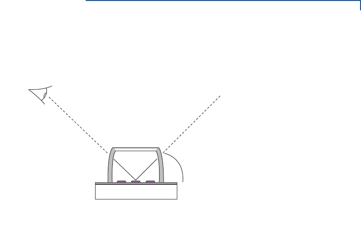
•The area of visibility should be no larger than a cone taken from the number 5
key at an angle of 45° and covering an area of 270° directly in front of the user,
as shown in Figure 1.
Figure 1 Pin Entry Visibility Area
CAUTION
The terminal is not waterproof or dustproof, and is intended for indoor use only.
Any damage to the unit from exposure to rain or dust may void any warranty.
270°
45°
SETUP
Selecting Unit Location
V200 NON-TOUCH INSTALLATION GUIDE 15
•You can secure PIN entry by installing a privacy shield (Figure 2).
Figure 2 PIN Entry Privacy Shield
PIN Protection
Measures
Several techniques can be employed to provide for effective screening of the PIN
entry keypad during the PIN entry process. These methods would typically be
used in combination, though in some cases a method might be used singly.
•Position the unit on the check-stand in such a way as to make visual
observation of the PIN entry process infeasible. Examples here include:
•Visual shields designed into the check-stand. These shields may be solely
for shielding purposes, or may be part of the general check-stand design.
•Position the PED so that it is angled in such a way that PIN spying
isdifficult.
•Installing the PED on an adjustable stand that allows consumers to swivel the
terminal sideways and/or tilt it forwards/backwards to a position that makes
visual observation of the PIN entry process difficult.
•Positioning of in-store security cameras so that the PIN entry keypad isnot
visible.
45° R

SETUP
Unpacking the Shipping Carton
16 V200 NON-TOUCH INSTALLATION GUIDE
The following table shows the combinations of methods that must be used when
installing the MX 900 Series terminal to protect the cardholder's PIN during PIN
entry.
Additionally, you may wish to implement the following to further increase security
during PIN entry.
•Offer PIN security literature at the point of sale
•Use signage to limit the view of the PED to just that of the cardholder
Privacy Shield
In order to comply with PCI, perform visual inspection of the terminal every 24
hours to ensure that the privacy shield is installed.
Unpacking the
Shipping Carton
Open the shipping carton and carefully inspect its contents for possible tampering
or shipping damage. The V200 Non-Touch is a secure product and any tampering
may cause the device to cease to function properly.
To unpack the
shipping carton 1Validate the authenticity of the sender by verifying the shipping tracking
number and other information located on the product order paperwork.
2Remove and inspect the following items:
•Terminal
•Power pack
•Telephone line cord
•Paper roll
Refer to Accessories and Documentation for more information about the
device’s related accessories.
3Remove all plastic wrapping from the terminal and other components.
Table 3 PIN Entry Protection Measures
Method
Observation Corridors
Cashier Customer Queue Customers
Elsewhere On-Site
Cameras
Countertop with
Swivel Stand
No Action Needed. Customer positions PED. No Action
Needed.
Do not install within
view of cameras.
Countertop without
stand
Position unit to face
away from the cashier.
Use signage to block
cashiers view.
Position unit between
customer and the next in
cue. Install the optional
privacy shield.
Privacy Shield
Installed.
Do not install within
view of cameras.
NOTE
The stand swivels to allow the cardholder to position the PED to optimize their
viewing angle. If the stand will be used, you must include prompts in your
application directing the cardholder to position the PED strategically to restrict the
view of others.
SETUP
Examining the Unit’s Features
V200 NON-TOUCH INSTALLATION GUIDE 17
4Remove the clear protective film from the display.
5Save the shipping carton and packing material for future repacking or moving
of the device.
Examining the
Unit’s Features
Before you continue the installation process, review the features of the device
(see Figure 3).
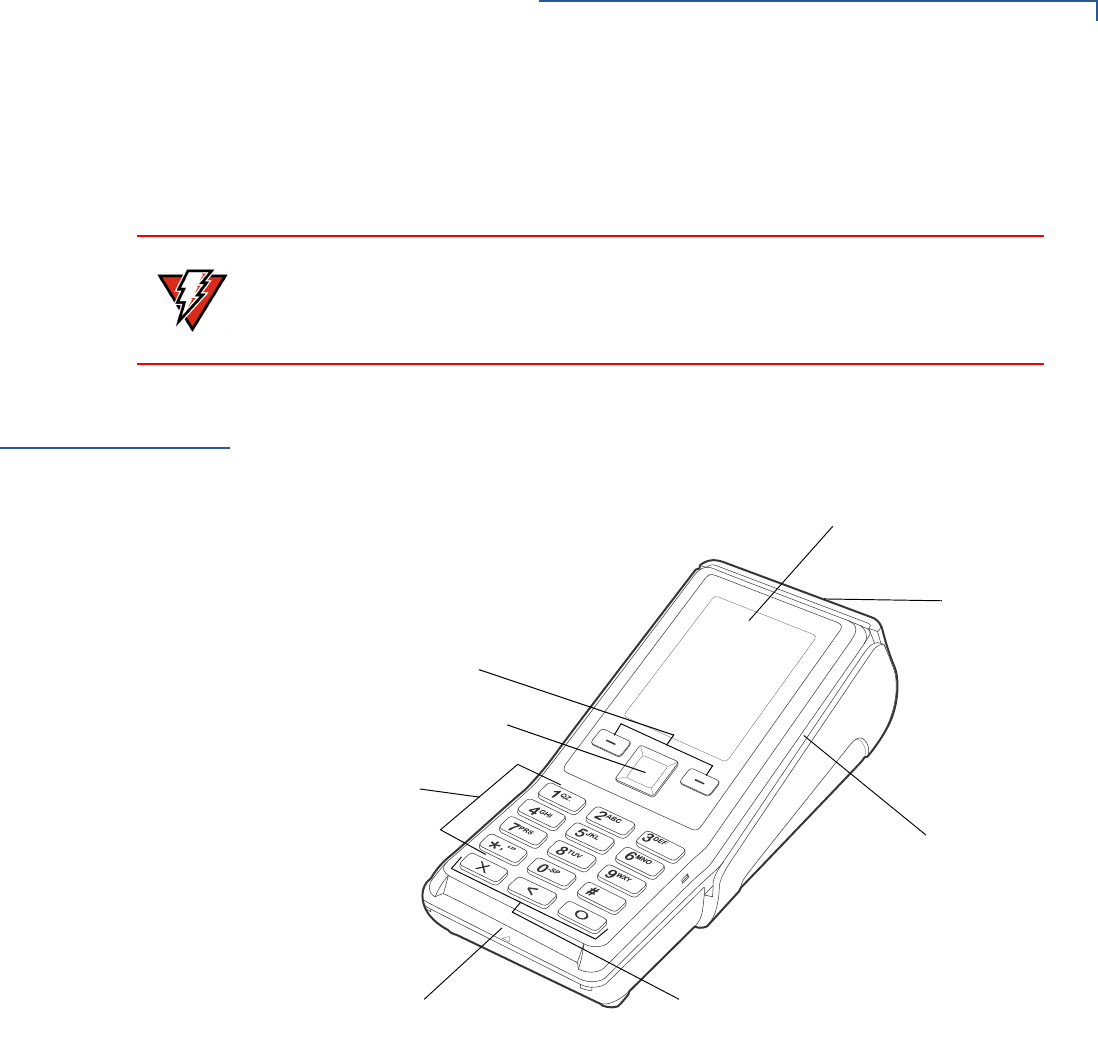
Figure 3 V200 Non-Touch Front View
Front Panel
The front panel includes the following features:
•A terminal display, backlit LCD screen. The screen also acts as the CTLS
tapping area for contactless transactions.
•Four sets of keys:
•A backlit 12-key, telephone-style keypad.
•Three color-coded function keys below the keypad (icons at right; from left
to right: CANCEL, BACKSPACE/CLEAR, ENTER).
•A four-way navigation button centered at the top of the keypad, below the
LCD screen.
WARNING
Do not use a unit that has been tampered with or otherwise damaged. This unit
comes equipped with tamper-evident labels. If a label or component appears
damaged, immediately notify the shipping company and your Verifone
representative or service provider.
NAVIGATION BUTTON
SELECTION KEYS
LCD SCREEN / CTLS TAPPING AREA
MAGNETIC CARD READER
SMART CARD READER
KEYPAD
FUNCTION KEYS
PRINTER
SETUP
Examining the Unit’s Features
18 V200 NON-TOUCH INSTALLATION GUIDE
•Two selection keys on the left and right side of the navigation button.
•A magnetic card reader, built into the right side. The icon shows the proper
swipe direction, with the stripe down and facing inward, toward the keypad.
•A smart card reader, built into the front of the terminal. The icon indicates
proper card position and insertion direction.
•The internal thermal printer opens toward the rear of the unit.
Connection Ports
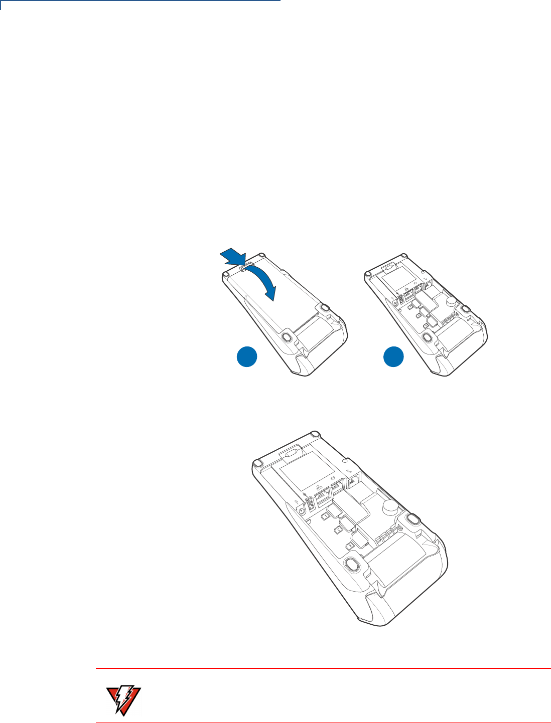
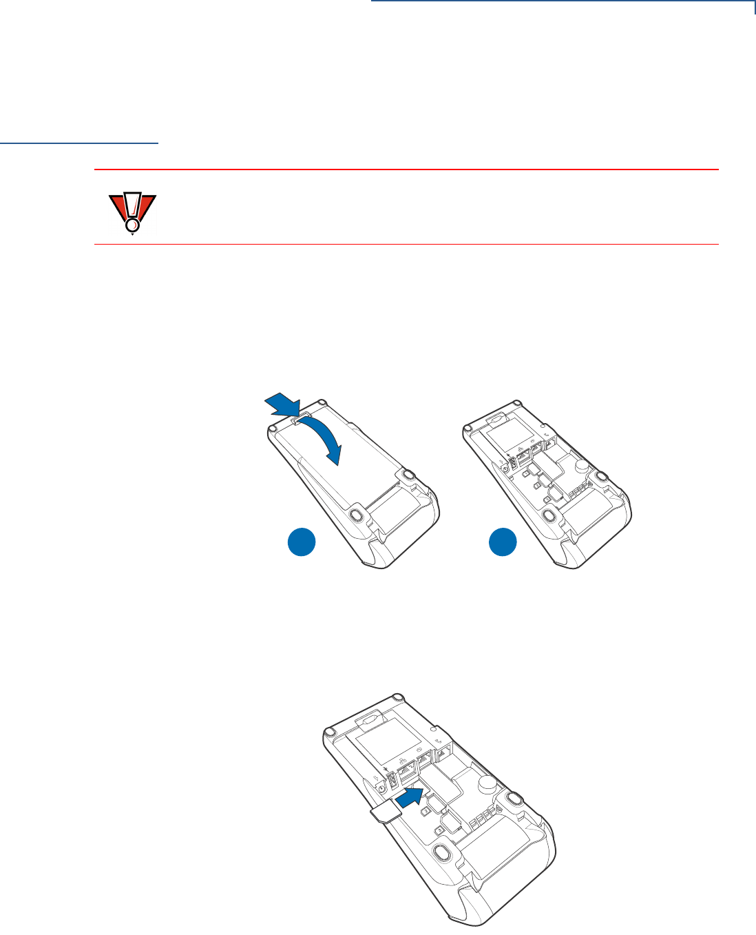
Turn the unit upside down and remove the rear cover to view the connection ports.
Notice that the ports are recessed. Different ports provide connections to a
communications line, optional peripheral devices, and the power supply.
Figure 4 shows how to open the rear cover of the V200 Non-Touch device.
Figure 4 Opening the Rear Cover
Figure 5 shows the power and connection ports for the V200 Non-Touch.
Figure 5 Power and Connection Ports
1
2
3
AB
WARNING
Do not connect the terminal to the power supply until all the peripherals are
attached.

SETUP
Examining the Unit’s Features
V200 NON-TOUCH INSTALLATION GUIDE 19
To use the
connection ports The connection ports offer multiple connectivity for the V200 Non-Touch terminal.
Please refer to the following list of peripheral devices for the connectivity options.
Host USB Port
•PIN Pads
•Barcode readers
•Biometric readers
•USB flash disk
•USB keyboards
Ethernet Port
•Ethernet cable to router, hub or switch
Client USB Port
•PCs
•ECR/Cash registers
Telco Port
•Telephone line with 56K modem
MOD 10 2-in-1 I/O port
•PIN Pads
•Computers
•ECRs
•Check readers
•CTLS readers
•Biometric readers
•Barcode readers
•Keyboards
For information on how to attach peripheral devices, see Connecting Optional
Devices.
NOTE
The MOD 10 2-in-1 I/O port supplies 11.6 V / 365 mA to power accessories (PIN
pads and powered RS-232 devices). It is SW configurable to USB 2.0 High
speed Host and supplies 5 V, 500 mA to external USB devices.
SETUP
Establishing Communication
20 V200 NON-TOUCH INSTALLATION GUIDE
Establishing
Communication
You can connect the V200 Non-Touch using the following options: By telephone
line and by ethernet cable.
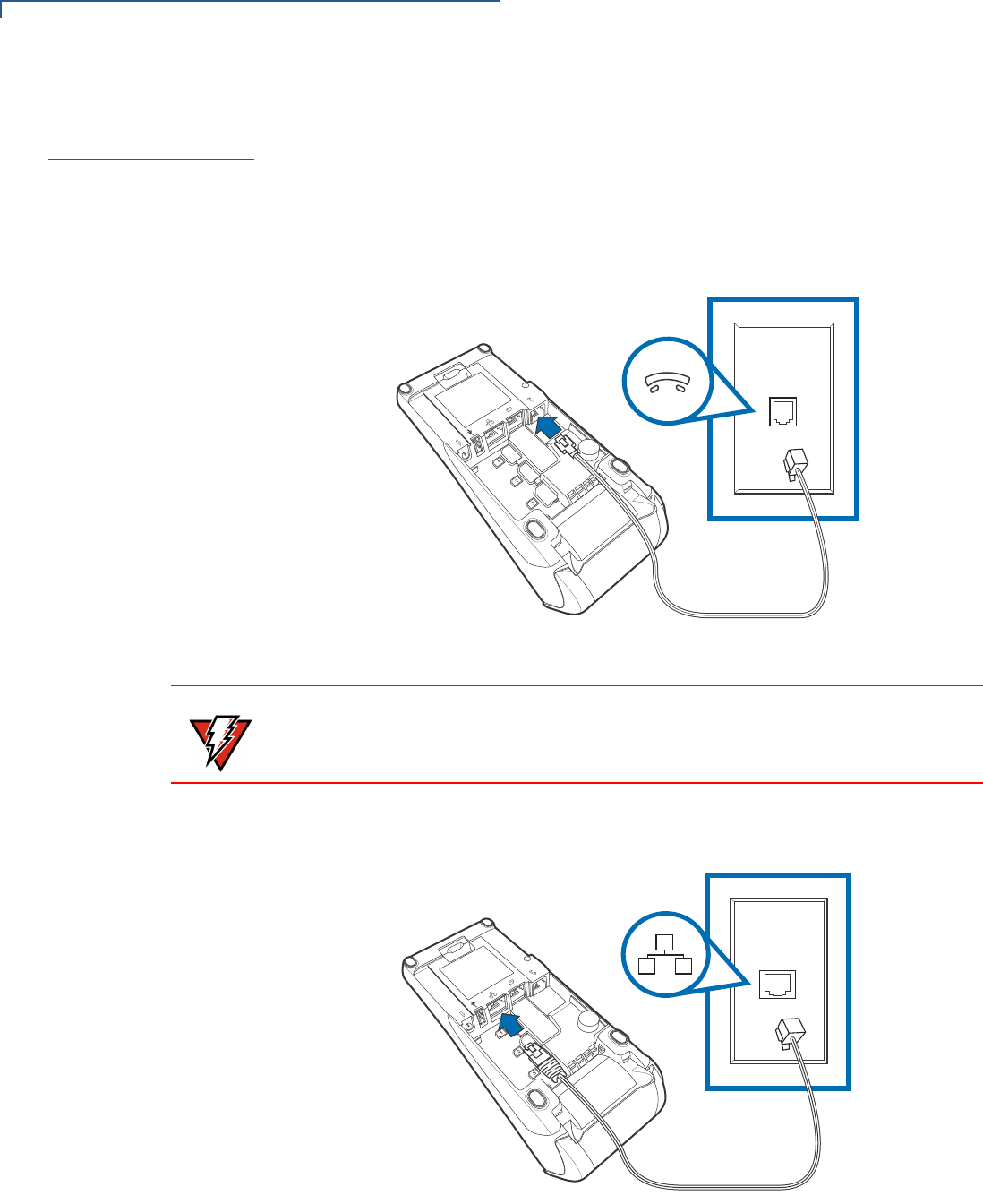
Connecting by
Telephone Line
Connect the telephone cord to the communication port on the terminal, then route
it directly to a telephone wall jack (see Figure 6). This is a direct connection and
the line is dedicated to the terminal.
Figure 6 Direct Telephone Connection
Connecting by
Ethernet Cable
Connect the ethernet cable to the ETH port on the terminal, then route it directly to
a network jack (see Figure 7). This is a direct connection to your network.
Figure 7 Ethernet Connection
WARNING
To reduce the risk of fire, use only No. 26AWG or larger UL Listed or CSA
Certified Telecommunication Line Cord.
SETUP
Loading a Paper Roll in the Printer
V200 NON-TOUCH INSTALLATION GUIDE 21
Loading a Paper
Roll in the
Printer
Before you can process transactions that require a receipt or record, you must
install paper in the printer.
The V200 Non-Touch uses a roll of 57 mm wide x 40 mm, single-ply, thermal
sensitive paper.
A pink out-of-paper indicator line appears on the edge of the paper before the end
of the roll. After this line appears, there is enough paper remaining on the roll to
conclude at least one more transaction.
To install a paper roll 1Hook your finger under the latch and lift up to swing the paper roll cover open
see Figure 8).
Figure 8 Opening the Printer Cover
2Remove any partial roll of paper in the printer tray by lifting it up.
3Loosen the glued leading edge of the new paper roll or remove the protective
strip. Unwind the paper roll past any glue residue.
4Hold the roll so the paper feeds from the bottom of the roll.
CAUTION
Poor-quality paper can jam the printer and create excessive paper dust. To order
high-quality Verifone paper, refer to Accessories and Documentation.
Store thermal paper in a dry, dark area. Handle thermal paper carefully: impact,
friction, temperature, humidity, and oils affect the color and storage
characteristics of the paper.
Never load a roll of paper with folds, wrinkles, tears, or holes at the edges.
)MAGE0LACEHOLDER/NLY
#ORRECT)LLUSTRATIONS#OMING3OON
SETUP
Loading a Paper Roll in the Printer
22 V200 NON-TOUCH INSTALLATION GUIDE
5Drop the paper roll into the printer tray.
Figure 9 Loading Paper Roll
6Pull paper up past the glue residue.
7Close the paper roll cover by gently pressing directly on the cover until it clicks
shut, allowing a small amount of paper past the glue residue to extend outside
the printer door. (see Figure 9).
Figure 10 Closing Paper Roll Cover
8Tear the paper off against the serrated metal strip in the printer.
)MAGE0LACEHOLDER/NLY
#ORRECT)LLUSTRATIONS#OMING3OON
CAUTION
To prevent the paper roll cover from damaging the print roller, always gently
press down on the printer dust cover to close it.
)MAGE0LACEHOLDER/NLY
#ORRECT)LLUSTRATIONS#OMING3OON
NOTE
For paper ordering information, refer to Accessories and Documentation.
SETUP
Installing or Replacing MSAM Cards
V200 NON-TOUCH INSTALLATION GUIDE 23
Installing or
Replacing MSAM
Cards
When you first receive your V200 Non-Touch, you may need to install one or more
MSAM cards or you may need to replace old cards.
To install or replace
MSAMs 1Remove the power pack from the power outlet.
2Place the terminal upside down on a soft, clean surface to protect the display
from scratches.
3Press the unlocking button and then lift the rear cover to access the MSAM
card slots.
Figure 11 Opening the V200 Non-Touch Rear Cover
4Remove any previously installed MSAM cards by sliding the card out from the
cardholder.
5Install an MSAM card by carefully sliding it into the slot until it is fully inserted.
Figure 12 Installing an MSAM Card
6Replace the terminal rear cover.
CAUTION
Observe standard precautions when handling electrostatically sensitive devices.
Electrostatic discharges can damage this equipment. Verifone recommends
using a grounded anti-static wrist strap.
1
2
3
AB
3!-
SETUP
Connecting Optional Devices
24 V200 NON-TOUCH INSTALLATION GUIDE
Connecting
Optional
Devices
The V200 Non-Touch device supports some peripheral devices designed for use
with electronic point-of-sale terminals.
Different terminals support different devices, so for more information about
optional devices, please contact your Verifone distributor.
Optional Device
Connections
The MOD 10 2-in-1 I/O port can operate either as a PIN pad port or an RS-232
port, depending on the power source available.
Connecting a PIN Pad
to the V200 Non-
Touch
Use the following procedures to connect a PIN pad or smart card reader.
1Remove the V200 Non-Touch rear cover.
2Insert the RJ45-type connector of the PIN pad or smart card reader into the
port of the peripheral device.
If a cable is not already connected to the smart card reader or PIN pad, insert
the small modular plug on one end of the interface cable into the optional
device’s modular jack.
3Insert the larger RJ45-type connector on the other end of the PIN pad cable
into the PIN pad serial port on the V200 Non-Touch. Figure 13 provides an
example of a PIN pad connection to the V200 Non-Touch.
Figure 13 Sample PIN Pad Connection
Connecting ECRs to
the V200 Non-Touch
The V200 Non-Touch also supports electronic cash registers (ECR).
CAUTION
Before connecting any peripheral device, remove the power plug from the
terminal. Reconnect the power cord only after you are finished connecting the
peripheral device(s). For complete information about peripheral installation and
use, refer to the user documentation supplied with those devices.
)MAGE0LACEHOLDER/NLY
#ORRECT)LLUSTRATIONS#OMING3OON
NOTE
Make sure you replace the rear cover when all cables are installed. This provides
some protection to the cables and connectors. Do not carry the terminal by the
installed cables or pull the terminal about the by the cables. This may cause a
cable to be removed or damage the cables.
SETUP
Connecting the Terminal Power Pack
V200 NON-TOUCH INSTALLATION GUIDE 25
Contact your Verifone representative or visit the online store at
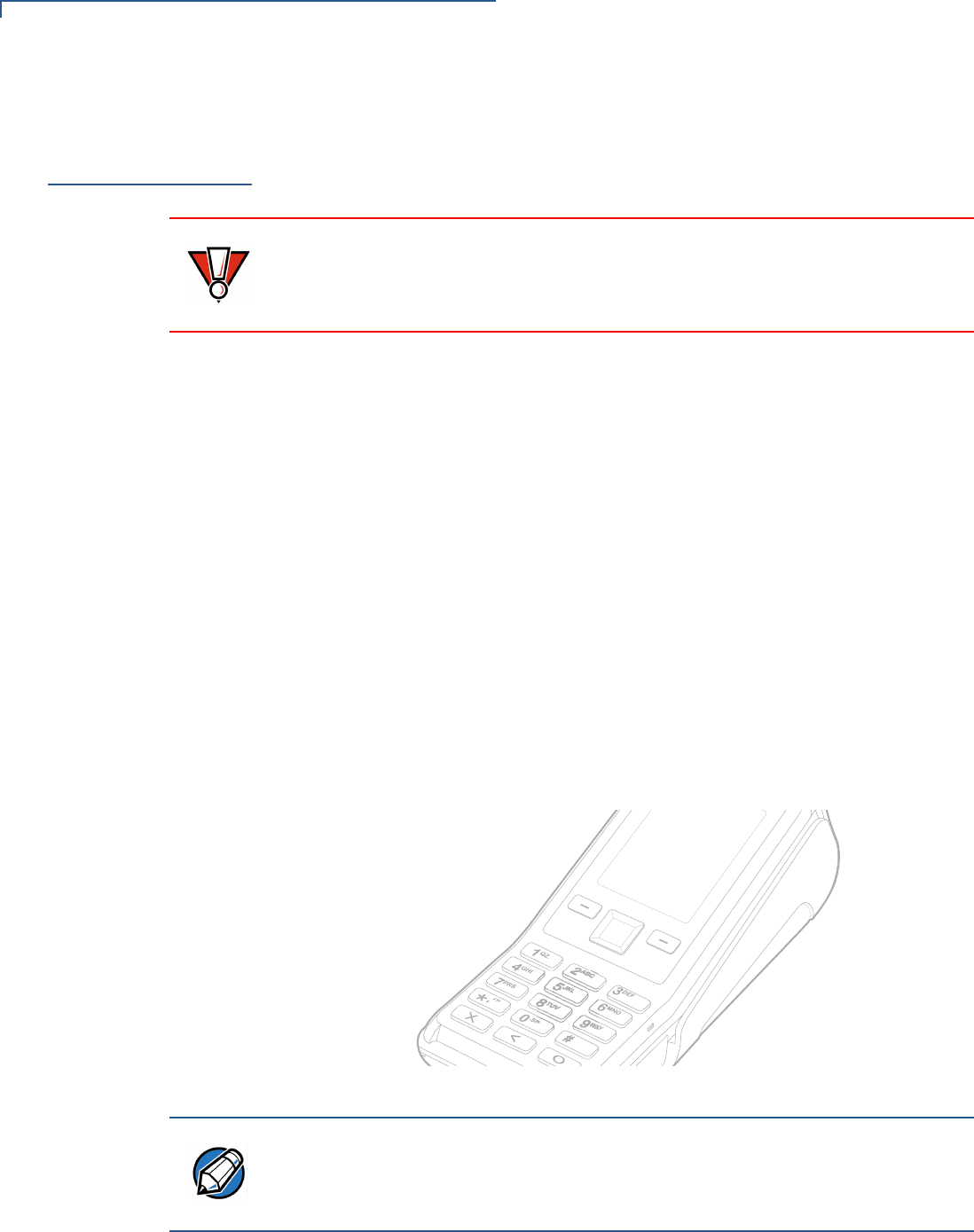
www.store.verifone.com for information on these devices.
The following illustration shows how to make a peripheral connection to the USB
port
Figure 14 Sample ECR Connection
Connecting the
Terminal Power
Pack
When you have finished connecting optional peripheral(s), you are ready to
connect the V200 Non-Touch to the provided power source.
To connect the
terminal power pack 1Remove the terminal rear cover to access the power port.
CAUTION
ECRs require a separate power source. Before connecting to an ECR or similar
device, remove the power cord from the V200 Non-Touch unit.
)MAGE0LACEHOLDER/NLY
#ORRECT)LLUSTRATIONS#OMING3OON
CAUTION
Using an incorrectly rated power supply may damage the terminal or cause it not
to work as specified. Before troubleshooting, ensure that the power supply being
used to power the terminal matches the requirements specified on the bottom of
the terminal. (See Chapter 3, Technical Specifications, for detailed power supply
specifications.) Obtain the appropriately rated power supply before continuing
with troubleshooting.
NOTE
Plugging in the power pack to a power source automatically turns on the
terminal.
SETUP
Connecting the Terminal Power Pack
26 V200 NON-TOUCH INSTALLATION GUIDE
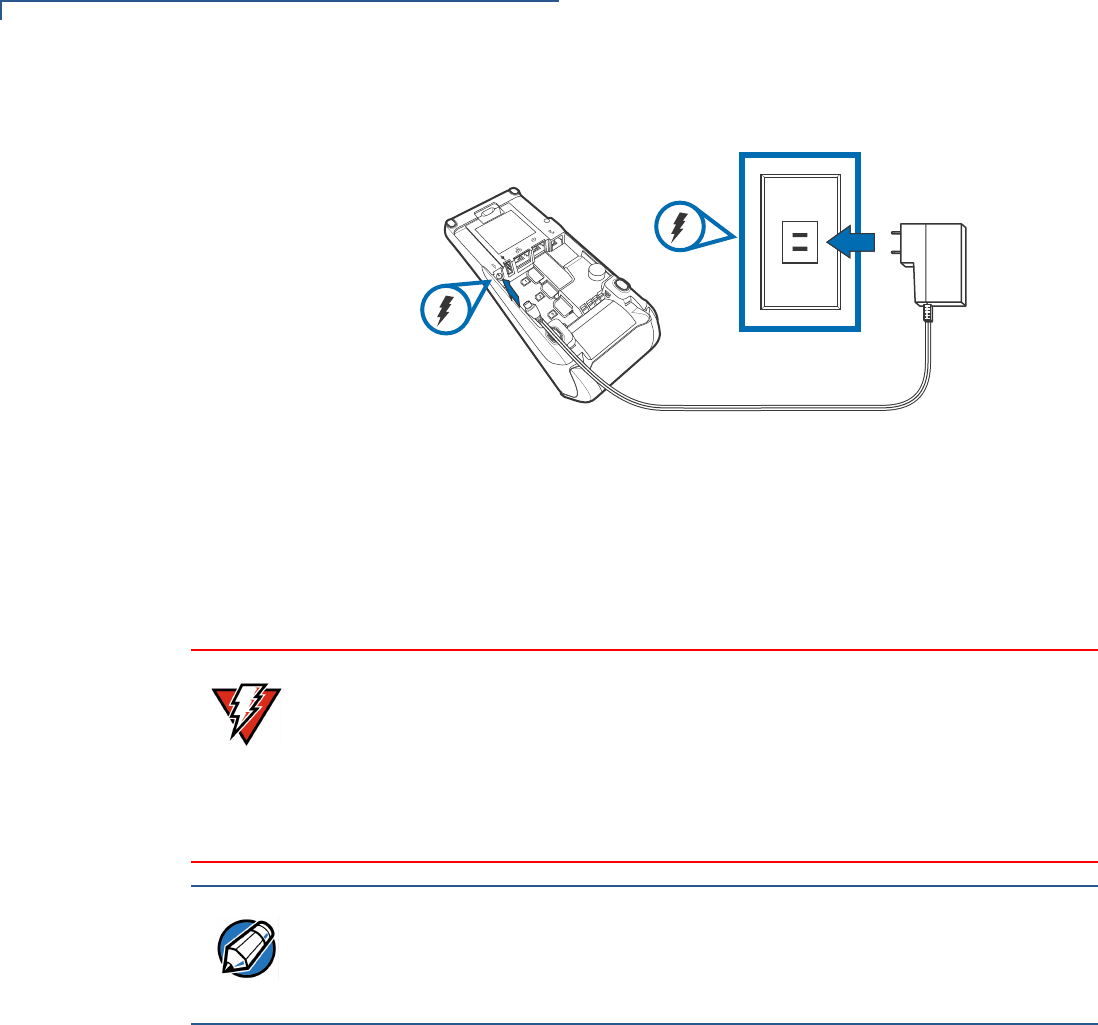
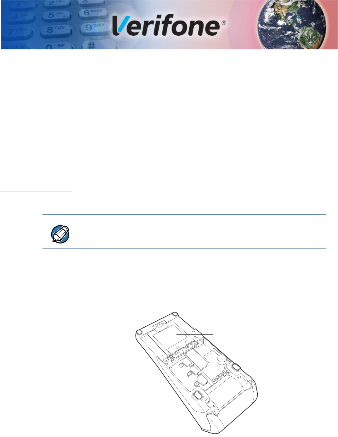
2Insert the round barrel connector (see Figure 15) into the power port.
Figure 15 Power Connection
3Route the cable in the direction of the arrow above the power port and sling
the cable over the underside of the thermal paper container.
4Close the terminal rear cover.
5Plug the AC power pack into a wall outlet or powered surge protector.
The terminal lights activate when the terminal has power.
If an application is loaded in the terminal, it starts after the initial Verifone copyright
screen and usually displays a unique copyright screen. If no application is loaded
in the terminal, DOWNLOAD NEEDED appears on screen after the initial Verifone
copyright screen.
WARNING
Do not plug the power pack into an outdoor outlet or operate the terminal
outdoors.
Disconnecting the power during a transaction may cause transaction data files
not yet stored in terminal memory to be lost.
To protect against possible damage caused by lightning strikes and electrical
surges, consider installing a power surge protector.
NOTE
Verifone recommends connecting wall power in the following order:
1Connect the terminal to the power supply.
2Connect the power supply to the power cord (if applicable).
3Connect the power cord to the wall outlet.
SETUP
Privacy Shield
V200 NON-TOUCH INSTALLATION GUIDE 27
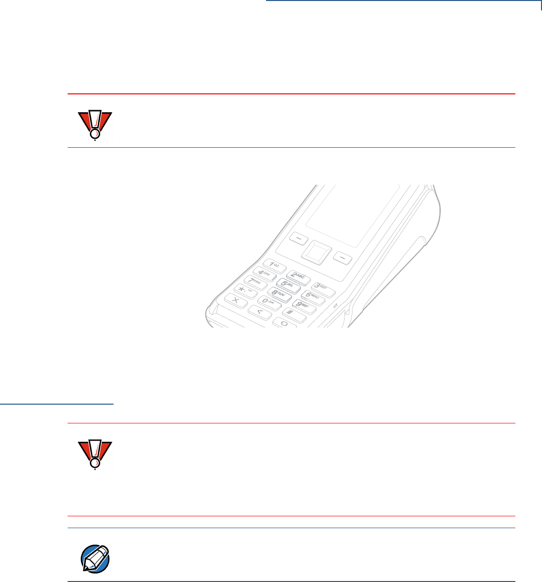
Privacy Shield
The privacy shield protects the customers’ PIN entry from being seen by the
cashier or other customers. The illustration (Figure 16) shows an example of a
V200 Non-Touch unit with a privacy shield.
Figure 16 Privacy Shield
Using the CTLS
Reader
The V200 Non-Touch function is only active when signaled by an application for
the conduction of a contactless smart card transaction.
To perform a
contactless smart
card transaction
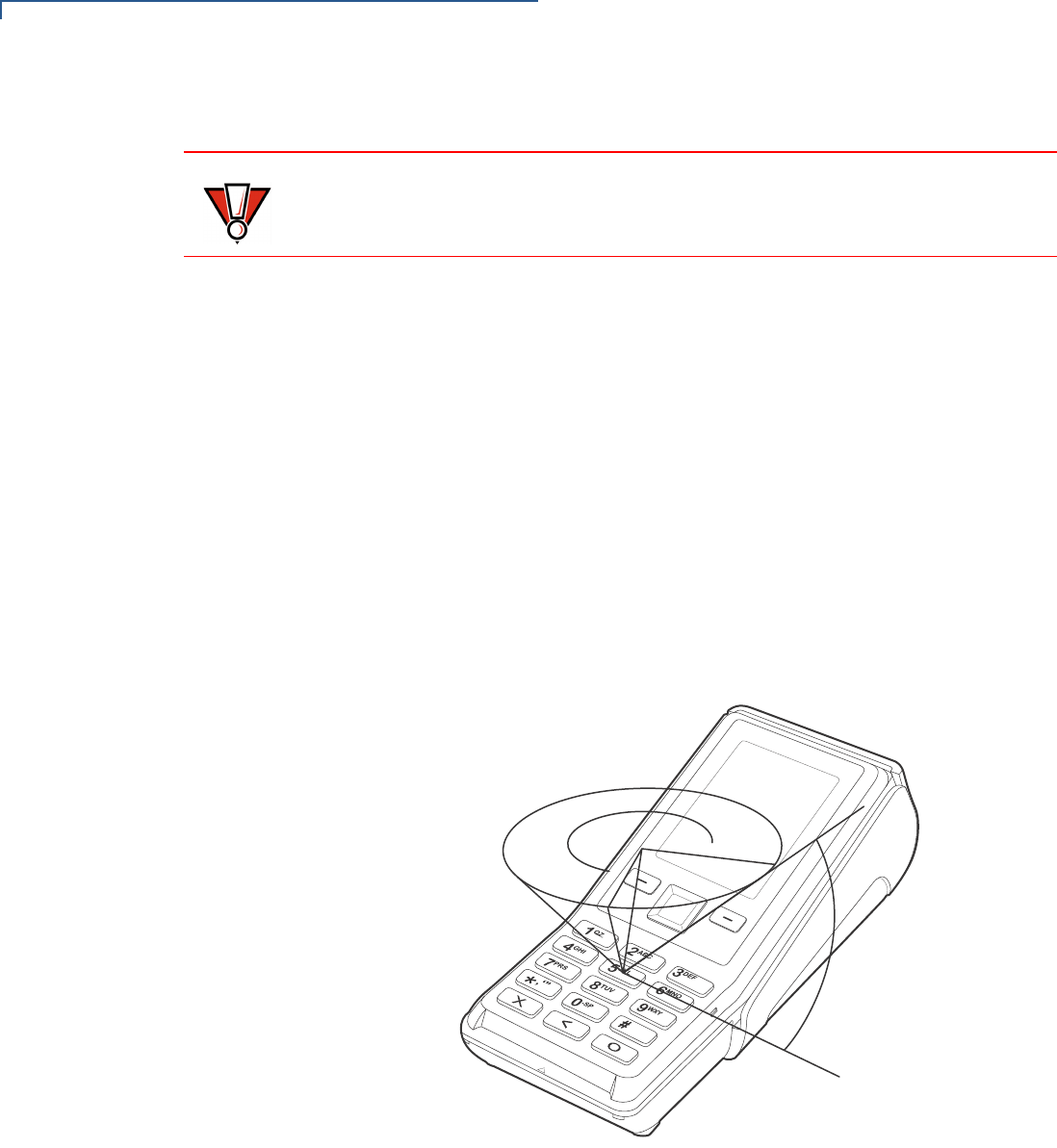
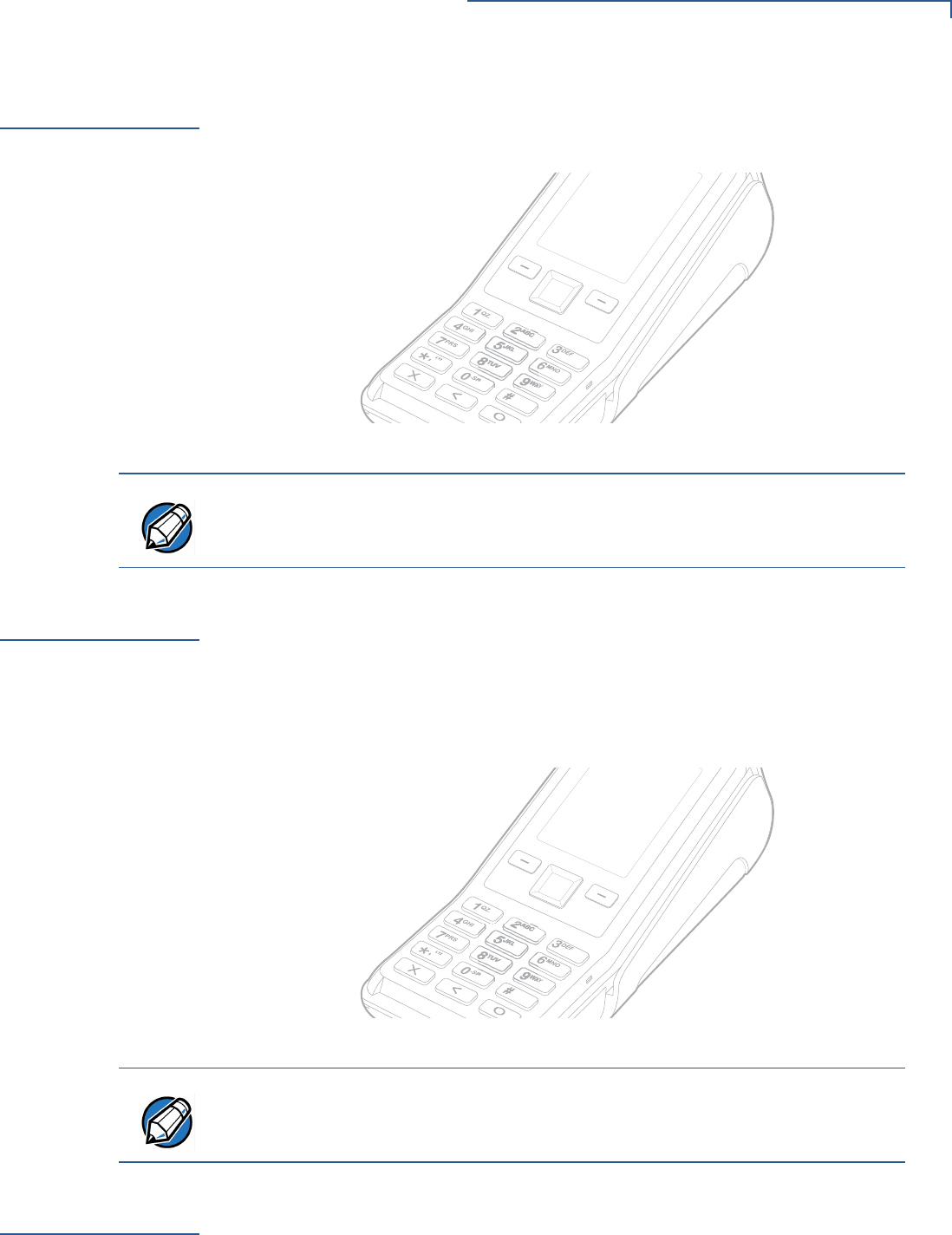
1Gently tap the card onto or hold the card (within 4 cm) against the surface of
the RFID canopy (see Figure 17).
2A short beeping sound indicates a successful transaction.
Figure 17 Using a CTLS Card
Using the Smart
Card Reader
The smart card transaction procedure may vary from one application to another.
Verify the procedure with your application provider before performing a smart card
transaction.
)MAGE0LACEHOLDER/NLY
#ORRECT)LLUSTRATIONS#OMING3OON
NOTE
Merchants who install the terminal without the privacy shield must ensure the
cardholder’s privacy when entering his PIN by positioning the terminal away from
open view.
)MAGE0LACEHOLDER/NLY
#ORRECT)LLUSTRATIONS#OMING3OON
NOTE
Follow proper care procedures to ensure the contactless module continues
working properly. Avoid exposing the module to metallic surfaces while in use.
SETUP
Using the Magnetic Card Reader
28 V200 NON-TOUCH INSTALLATION GUIDE
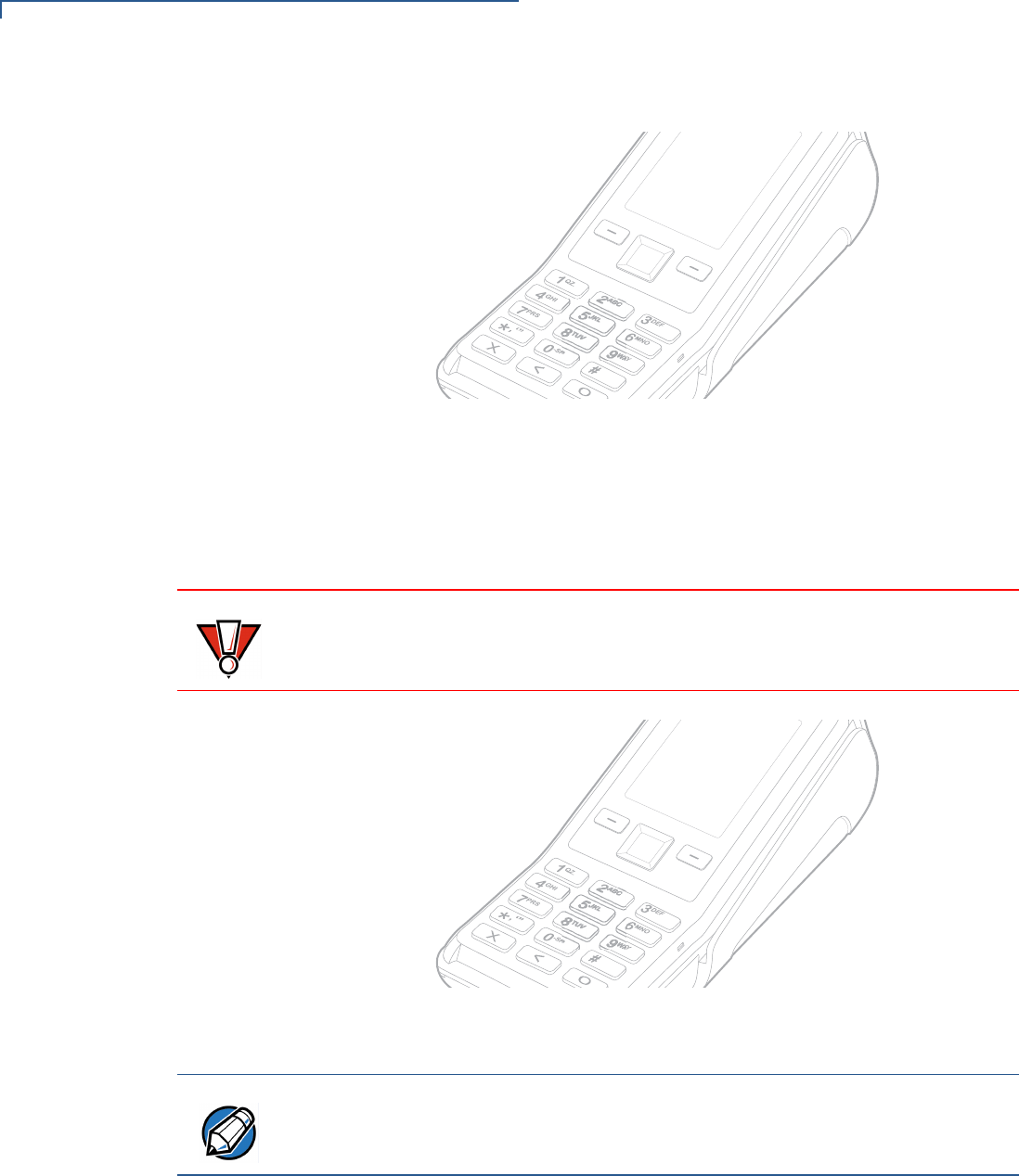
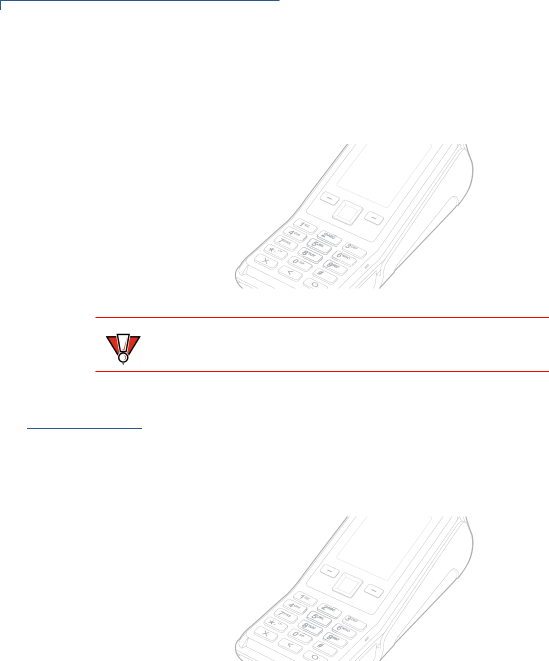
To conduct a smart
card transaction 1Position a smart card with the contacts facing upward (see Figure 18).
2Insert the smart card into the smart card reader slot in a smooth, continuous
motion until it seats firmly.
3Remove the card only when the application indicates the transaction is
complete.
Figure 18 Inserting a Smart Card
Using the
Magnetic Card
Reader
The V200 Non-Touch terminal supports credit or debit card transactions.
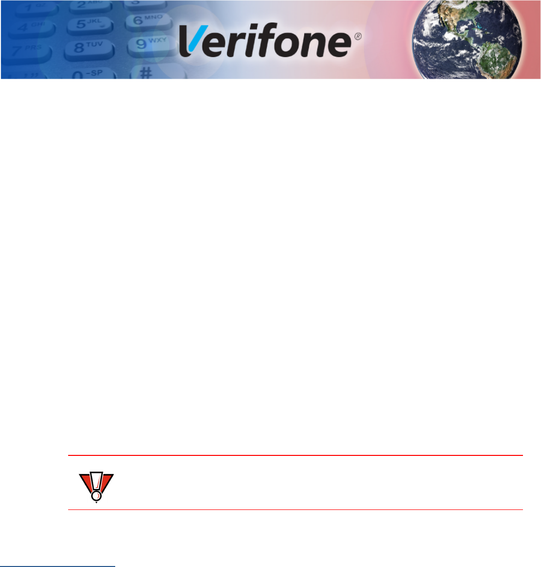
To conduct a credit or
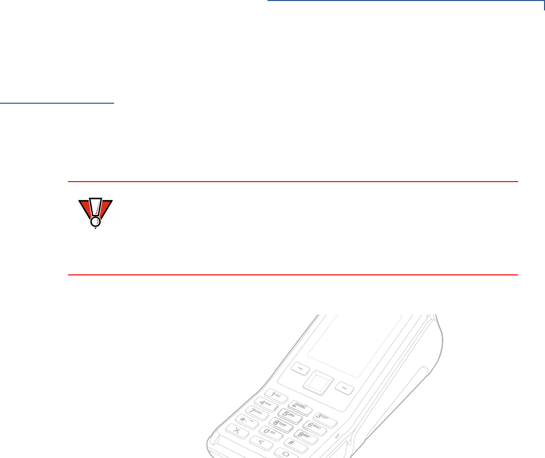
debit card transaction 1Position the card with the stripe in the card reader and facing inward, toward
the keypad.
2To ensure a proper read of the magnetic swipe card, the user should insert the
magnetic card from the top of the unit, as shown in Figure 19.
Figure 19 Using the Magnetic Card Reader
3Swipe the card through the magnetic card reader.
)MAGE0LACEHOLDER/NLY
#ORRECT)LLUSTRATIONS#OMING3OON
CAUTION
Leave the smart card in the card reader until the transaction is complete.
Premature card removal will invalidate the transaction.
)MAGE0LACEHOLDER/NLY
#ORRECT)LLUSTRATIONS#OMING3OON

SETUP
Periodic Inspection
V200 NON-TOUCH INSTALLATION GUIDE 29
Periodic
Inspection
Periodically inspect the terminal for possible tampering. Signs of tampering
include:
•Wires protuding out of the device.
•Foreign objects inserted into the smartcard slot or magnetic stripe slot.
•Signs of damage to the tamper evident labels
•Warning message on the device display
If any device is found in tamper state, please remove it from service immediately,
keep it available for potential forensics investigation, and notify your company
security officer and your local Verifone representative or service provider. For
contacting Verifone, please see section “Service and Support”.
For terminals equipped with a privacy shield, perform daily inspections to ensure
that the privacy shield is installed.

SETUP
Periodic Inspection
30 V200 NON-TOUCH INSTALLATION GUIDE

V200 NON-TOUCH INSTALLATION GUIDE 31
CHAPTER 3
Specifications
This chapter discusses power requirements, dimensions, and other specifications
of the V200 Non-Touch unit.
Technical
Specifications
Refer to the following information on the power, weight, temperature, memory,
ports and other technical details about your V200 Non-Touch unit.
Unit Power
Requirements
•Input power rating: 11.6 V DC, 1.55 A.
•External universal-input 18 W power supply, compliant with Energy Efficiency.
Temperature
•Operating Environment: 0°C to +50 °C (32 °F to 122 °F)
•Non-Operating Environment: -20 °C to +60°C (- 4 °F to 140 °F)
•Relative humidity: 5% to 90% RH non-condensing
Memory
•128MB DDRAM, 256MB NAND-Flash (V200 Non-Touch)
•512MB DDRAM, 256MB NAND-Flash (V200 Non-Touch Plus)
Magnetic Stripe
Card
•Triple-track
•Supports bi-directional card read, swipe speed at 10 IPS to 40 IPS
Smart Card Reader
•Non-sliding
•Card conserving plated landing contacts
•SC voltage 1.8V, 3.0V, 5.0V
SAM Requirements
•2 SAM slots
•ID-000 format
Communication
•Ethernet
•Speed 10 Base-T /100 Base-TX
•Compliant with IEEE802.3 LAN networks.
NOTE
If this device is to be used in the Nordic countries, or in any environment where
the temperature range exceeds the product’s operating temperature, it is the
responsibility of the integrators to ensure that the ambient environment is
controlled in such a way to ensure that the product operates within the specified
temperature range.

SPECIFICATIONS
Technical Specifications
32 V200 NON-TOUCH INSTALLATION GUIDE
•Dial modem
•Modem: Conexant Boulevard CX93040-1X
•DAA: Conexant CX20548
•Host interface SPI
•V.92 standard supported, line speeds from 2400 Kbps to 56 Kbps.
•USB
•USB2.0 high speed
•USB Host/Device configurable by SW
•Supports 5 V/500 mA to external USB device.
•MOD 10 2-in-1 I/O port
•Integrates RS-232, USB2.0 Host / Device IO ports into a 10-pin RJ45
connector.
•Uses VFI customized extension cable to access USB host port or USB
device port. The extension cable is not a standard in-box accessory.
•Supports Biometrics and Barcode reader via MOD 10 connector.
Display
•2.8 inch portrait mode transmissive TFT LCD, RGB stripe (QVGA, 240 RGB x
320 dots)
•RGB data bus interface, 18 bit Parallel Data
•Software controllable back-light
•SPI interface for LCM controller.
Thermal Printer
•Support 30 LPS for first 30 sec, and then printing speed will slow down to
meet 18 W power budget.
•Supports 57 mm wide x 40 mm diameter paper roll
•Out-of-Paper Sensor.
SD Memory (Media
version only)
•4 bit SDIO interface
•Up to 192 Mbps in High-Speed SD mode, 4 bit data transfer
•Supports card detect and write protect
•Speed Class: SDHC Class 2, 4, 6 and 10
V200 NON-TOUCH INSTALLATION GUIDE 33
CHAPTER 4
Maintenance and Cleaning
Your V200 Non-Touch should be treated with care. It has no user-serviceable
parts.
The following suggestions will help you protect your warranty coverage.
•Do not store the device in hot areas. High temperatures can shorten the
life of electronic devices, damage batteries and warp or melt certain
plastics.
•Do not store the device in cold areas. When the device returns to its
normal temperature, moisture can form inside the device and damage
electronic circuit boards.
•Do not drop, knock, or shake the device. Rough handling can break
internal circuit boards and fine mechanics.
•Do not use harsh chemicals, cleaning solvents or strong detergents to
clean the device. Use only a soft, clean, dry cloth for cleaning.
These suggestions apply equally to your device, or any of its attachments or
accessories. If your device is not working properly, take it to the nearest Verifone-
authorized service provider for servicing or replacement.
Additional
Safety
Information
The following is additional information for your safety in using this device.
Potentially
Explosive
Environments
When using the device in areas with potential risk of explosion, such as petrol
stations, follow the advice of all signs and instructions. If there has been a leak, do
not use this device.
CAUTION
Never use thinner, trichloroethylene, or ketone-based solvents – they can
deteriorate plastic or rubber parts.

MAINTENANCE AND CLEANING
Additional Safety Information
34 V200 NON-TOUCH INSTALLATION GUIDE
V200 NON-TOUCH INSTALLATION GUIDE 35
CHAPTER 5
Service and Support
For V200 Non-Touch problems, contact your local Verifone representative or
service provider.
For device product service and repair information:
•USA – Verifone Service and Support Group, 1-800-834-4366,
Monday - Friday, 8 A.M. - 8 P.M., eastern time.
•International – Contact your Verifone representative.
Service Returns
Before returning the unit to Verifone, you must obtain a Merchandise Return
Authorization (MRA) number. The following procedure describes how to return
one or more card reading units for repair or replacement (U.S. customers only).
1Gather the following information from the printed labels (see Figure 20) on the
underside of each unit to be returned:
•Product ID, including the model and part number. For example,
“Mabx-xxx-xx-xxx” and “PTID xxxxxxxx.”
•Serial number (S/N xxx-xxx-xxx).
Figure 20 Information Labels on Unit
2Within the United States, call Verifone toll-free at 1-800-834-4366.
NOTE
International customers, please contact your local Verifone representative for
assistance with your service, return, or replacement.
SERIAL NUMBERS
MODEL AND

SERVICE AND SUPPORT
Accessories and Documentation
36 V200 NON-TOUCH INSTALLATION GUIDE
3Select the MRA option from the automated message. The MRA department is
open Monday–Friday, 8 A.M.–8 P.M., eastern time.
4Give the MRA representative the information gathered in Step 1.
If the list of serial numbers is long, you can fax the list, along with the
information gathered in Step 1, to the MRA department at 1-727-953-4172
(U.S.).
•Please address the fax clearly to the attention of the “Verifone MRA Dept.”
•Include a telephone number where you can be reached and your fax
number.
•You will be issued MRA number(s) and the fax will be returned to you.
5Describe the problem(s) and provide the shipping address where the repaired
or replacement unit must be returned.
6Keep a record of the following items:
•Assigned MRA number(s).
•Verifone serial number assigned to the unit you are returning for service or
repair (serial numbers are located on the top of the unit,
(see Figure 20).
•Shipping documentation, such as air bill numbers used to trace the
shipment.
•Model(s) returned (model numbers are located on the Verifone label on the
top of the unit).
Accessories and
Documentation
Verifone produces accessories and documentation for the card reader. When
ordering, please refer to the part number in the left column.
Verifone Online Store at www.store.verifone.com
•USA – Verifone Customer Development Center, 1-800-834-4366,
Monday - Friday, 7 A.M. - 8 P.M., eastern time
•International – Contact your Verifone representative
NOTE
One MRA number must be issued for each unit you return to Verifone, even if
you are returning several of the same model.

SERVICE AND SUPPORT
Accessories and Documentation
V200 NON-TOUCH INSTALLATION GUIDE 37
Connection Cables
Power Cables
Cleaning Kit
Documentation
CBL159-312-01-A LAN cable for Ethernet connections.
CBL420-001-01-A RJ45 + USB type A cable
CBL420-002-02-A RJ45 + USB mini B cable
26264-01-R Cash register cable, RJ45-SUBD9f, 1.0m.
26264-02-R Cash register cable, RJ45-SUBD9f, 2.0m.
PWR420-001-01-A 18 W power pack.
02746 Verifone Cleaning Kit.
VPN DOCxxx-xxx-EN V200 Non-Touch Certifications and Regulations Sheet
VPN DOCxxx-xxx-EN V200 Non-Touch Quick Installation Guide
VPN DOCxxx-xxx-EN V200 Non-Touch Reference Guide

SERVICE AND SUPPORT
Accessories and Documentation
38 V200 NON-TOUCH INSTALLATION GUIDE
V200 NON-TOUCH INSTALLATION GUIDE 39
CHAPTER 6
Troubleshooting
Guidelines
This chapter lists possible malfunctions that may occur while operating a V200
Non-Touch device and recommends appropriate corrective actions. If the problem
persists - even after performing the outlined guidelines, or if the problem is not
described, contact your local Verifone representative for assistance.
Blank Display
When the terminal display screen does not show correct or clearly readable
information:
•Check terminal power connection.
•Remove and reapply power to the terminal.
•Check the battery status.
•Check all cable connections and verify that the telephone line is properly
connected.
•If the problem persists, contact your local Verifone service provider.
Terminal Does
Not Dial Out
If the terminal does not dial out:
•Check the telephone line connections.
•Check that the telephone line is working by plugging it into a working
telephone and listening for a dial tone.
•Replace the telephone cable that connects the terminal with a cable you know
is working correctly.
•Verify that a modem profile is present. The modem will not function without a
modem profile.
•If the problem persists, contact your local Verifone service provider.
NOTE
The unit comes equipped with tamper-evident labels. The reader contains no
user-serviceable parts. Do not, under any circumstance, attempt to disassemble
the unit. Perform only those adjustments or repairs specified in this guide. For all
other services, contact your local Verifone service provider. Service conducted by
parties other than authorized Verifone representatives may void any warranty.
CAUTION
Using an incorrectly rated power supply may damage the unit or cause it to not
work properly. Before troubleshooting, ensure that the power supply used to
power the unit matches the specified requirements (see Specifications for
detailed power supply specifications). If not, obtain the appropriately rated power
supply before continuing with troubleshooting.

TROUBLESHOOTING GUIDELINES
Printer Paper Jam
40 V200 NON-TOUCH INSTALLATION GUIDE
Printer Paper
Jam
If paper jams inside the printer:
1Open the paper roll cover.
2Remove the damaged paper from the paper roll and clear the feed
mechanism.
3Install printer paper.
4If the problem persists, it may be due to poor paper quality. Install a new roll of
higher-quality paper.
Keypad Does
Not Respond
If the keypad does not respond properly:
•Check the terminal display. If it displays the wrong character or nothing at all
when you press a key, follow the steps outlined in Transactions Fail To
Process.
•If pressing a function key does not perform the expected action, refer to the
user documentation for that application to ensure you are entering data
correctly.
•If the problem persists, contact your local Verifone representative.
Peripheral
Device Does Not
Work
If any peripheral device (PIN pad or smart card reader) does not work properly:
•Check the power cord connection to the peripheral device.
•Check that the device connected to the proper port has power and is
functioning properly. If possible, perform a self-test on the device in question.
•The cable connecting the optional device to the terminal serial port may be
defective. Try a different serial cable. See Connecting Optional Devices.
•If the problem persists, contact your local Verifone representative.
Transactions
Fail To Process
There are several reasons why the card reader may not be processing
transactions. Use the following steps to troubleshoot failures.
Check the Magnetic Card Reader
•Perform a test transaction using one or more different magnetic stripe cards to
ensure the problem is not a defective card.
•Ensure that you are swiping cards properly. With the card reader, the black
magnetic stripe should face down.
CAUTION
Poor-quality paper may jam the printer. To order high-quality Verifone paper, refer
to Accessories and Documentation.

TROUBLESHOOTING GUIDELINES
Printer Does Not Print
V200 NON-TOUCH INSTALLATION GUIDE 41
•If possible, process a transaction manually, using an external keypad, instead
of the card reader. If the manual transaction works, the problem may be a
defective reader.
•If the manual transaction does not process, proceed to Check the Telephone
Line.
•If the problem persists, contact your local Verifone representative.
Check the Smart Card Reader
•Perform a test transaction using several different smart cards to ensure the
problem is not a defective card.
•Ensure that the card is inserted correctly and that the card is not removed
prematurely.
•Ensure the SAM cards are properly inserted in the cardholders and that the
cardholders are properly secured (see Installing or Replacing MSAM Cards).
•If the manual transaction does not process, proceed to Check the Telephone
Line.
•If the problem persists, contact your local Verifone representative.
Check the Telephone Line
•Disconnect the telephone line from the terminal and connect it to a working
telephone to check for a dial tone. If there is no dial tone, replace the
telephone cable.
•If the problem appears to be with the telephone line, check with the party you
are trying to call to see if their system is operational. If they are not
experiencing difficulties with their line, contact the telephone company and
have your line checked.
•If the telephone line works, contact your local Verifone representative for
assistance.
Printer Does Not
Print
If the printer does not work properly:
•Check terminal power connection.
•Check if the printer is out of paper and that the roll is properly installed. Open
the paper roll cover and install a new roll of printer paper or ensure that the roll
is feeding from the bottom.
•Verify that the printer roller and paper roll dust cover are properly installed.
•If the problem persists, contact your Verifone distributor or service provider.
NOTE
The V200 Non-Touch reads the card upon card removal or withdrawal from the
slot.

TROUBLESHOOTING GUIDELINES
Terminal Display Does not Show Correct or Readable Information
42 V200 NON-TOUCH INSTALLATION GUIDE
Terminal Display
Does not Show
Correct or
Readable
Information
•Connect the terminal in to a known-good power supply (if you have one) to
see if this clears the problem.
•If the problem persists, contact your local Verifone representative for
assistance.
V200 NON-TOUCH INSTALLATION GUIDE 43
CHAPTER 7
Port Pinouts
This section contains port pinout tables for the V200 Non-Touch.
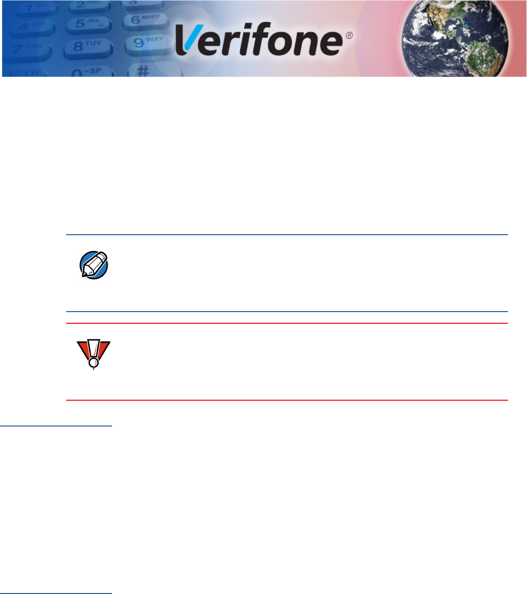
RS-232 Port (COM1)
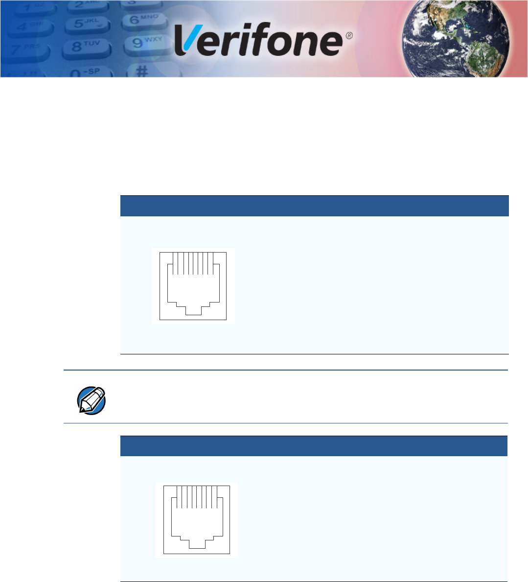
Ethernet Port
(LAN)
Connector PIN Function Description
1Portpwr (9 to12
V DC)
Port power (11.6V typ.,
365mA)
2NC No connection
3NC No connection
4GND Power ground
5RXD Receive data
6TXD Transmit data
7NC No connection
8NC No connection
18
NOTE
The 10-pin download cable (VPN 26264) connects to the 8-Pin RS-232 port of
the device, wherein Pin 2 from the cable corresponds to Pin 1 on the RS-232
port.
Connector PIN Function Description
1TXD+ Transmit data +
2TXD- Transmit data -
3RXD+ Receive data +
4NC No connection
5NC No connection
6RXD- Receive data -
7NC No connection
8NC No connection
18
PORT PINOUTS
44 V200 NON-TOUCH INSTALLATION GUIDE
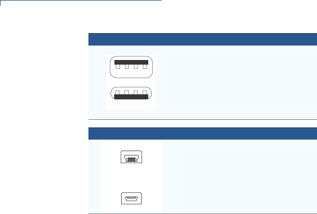
USB Pinout
(Host Port)
USB Pinout
(Client Port)
Connector PIN Function Description
1+5 V 5 V USB Power (500 mA)
2DATA- USB Host Signal -
3DATA+ USB Host Signal +
4GND USB ID pin/Ground
Receptacle
Plug
14
14
Connector PIN Function Description
15 V 0 5 V USB Power
2DATA- USB Device Signal -
3DATA+ USB Device Signal +
4
5GND USB Ground
Receptacle
Plug
15
15

V200 NON-TOUCH INSTALLATION GUIDE 45
APPENDIX A
Caution and Warning Messages
V200 Non-Touch
Caution and
Warning
Messages
Products with UL/cUL certification include French translations of Caution and
Warning notices. The following table lists all notices found in the document, their
location and the equivalent French translations.
Table 4 Caution and Warning Messages
Notice Chapter Page English Text French Text
Caution Setup page
14
The terminal is not waterproof or
dustproof, and is intended for
indoor use only.
Any damage to the unit from
exposure to rain or dust may void
any warranty.
Le terminal est pas étanche ou à la
poussière, et est destiné à une utilisation
en intérieur.
Tout dommage à l'unité de l'exposition à
la pluie ou à la poussière peut annuler la
garantie.
Warning Setup page
15
Do not use a unit that has been
tampered with or otherwise
damaged. This unit comes
equipped with tamper-evident
labels. If a label or component
appears damaged, immediately
notify the shipping company and
your Verifone representative or
service provider.
Ne pas utiliser une unité qui a été altéré
ou endommagé. Cet appareil est équipé
d' étiquettes inviolables. Si une étiquette
ou d'un composant semble endommagé,
avertissez immédiatement la compagnie
de navigation et votre représentant ou du
prestataire de services Verifone.
Warning Setup page
17
Do not connect the terminal to the
power supply until all the
peripherals are attached.
Ne pas connecter le terminal à
l'alimentation jusqu'à ce que tous les
périphériques sont branchés.
Warning Setup page
19
To reduce the risk of fire, use only
No. 26AWG or larger UL Listed or
CSA Certified Telecommunication
Line Cord.
Pour réduire le risque d' incendie, utilisez
uniquement No. 26AWG ou plus cordon
certifiés CSA télécommunications UL ou.

CAUTION AND WARNING MESSAGES
V200 Non-Touch Caution and Warning Messages
46 V200 NON-TOUCH INSTALLATION GUIDE
Caution Setup page
20 Poor-quality paper can jam the
printer and create excessive paper
dust. To order high-quality Verifone
paper, refer to Accessories and
Documentation.
Store thermal paper in a dry, dark
area. Handle thermal paper
carefully: impact, friction,
temperature, humidity, and oils
affect the color and storage
characteristics of the paper.
Never load a roll of paper with
folds, wrinkles, tears, or holes at
the edges.
Papier de mauvaise qualité peut
provoquer un bourrage et de créer
excessive de poussière de papier. Pour
commander - papier de haute qualité
Verifone, consultez Accessoires et
documentation.
Gardez le papier thermique dans un
endroit sombre . Manipulez le papier
thermique attentivement: impact, friction,
la température, l'humidité et les huiles
affectent les caractéristiques de couleur
et de stockage du papier.
Ne jamais charger un rouleau de papier
avec des plis, des larmes, ou des trous
sur les bords.
Caution Setup page
21 To prevent the paper roll cover
from damaging the print roller,
always gently press down on the
printer dust cover to close it.
Pour éviter que le couvercle du rouleau
de papier d'endommager le rouleau
d'impression, toujours appuyez
doucement sur le capot de protection de
l'imprimante pour le fermer.
Caution Setup page
21 Observe standard precautions
when handling electrostatically
sensitive devices. Electrostatic
discharges can damage this
equipment. Verifone recommends
using a grounded anti-static wrist
strap.
Respecter les précautions standard lors
de la manipulation des appareils
sensibles aux décharges électrostatiques.
Les décharges électrostatiques peuvent
endommager cet équipement. Verifone
recommande d'utiliser un bracelet anti-
statique à la terre.
Caution Setup page
22 Before connecting any peripheral
device, remove the power cord
from the terminal and ensure that
the green indicator LED is not lit.
Reconnect the power cord only
after you are finished connecting
the peripheral device(s). For
complete information about
peripheral installation and use,
refer to the user documentation
supplied with those devices.
Avant de connecter un périphérique,
débranchez le cordon d'alimentation de la
borne et de veiller à ce que la LED témoin
verte est pas allumé Rebranchez le
cordon d'alimentation seulement après
que vous avez terminé de connecter le
périphérique (s) périphérique. Pour des
informations complètes sur l'installation et
l'utilisation périphérique, reportez-vous à
la documentation utilisateur fournie avec
ces périphériques.
Caution Setup page
23 ECRs require a separate power
source. Before connecting to an
ECR or similar device, remove the
power cord from the V200 Non-
Touch unit.
ECR nécessitent une source
d'alimentation séparée. Avant la
connexion à un ECR ou un dispositif
similaire, débranchez le cordon d'
alimentation de l'appareil V200 Non-
Touch.
Table 4 Caution and Warning Messages (continued)
Notice Chapter Page English Text French Text

CAUTION AND WARNING MESSAGES
V200 Non-Touch Caution and Warning Messages
V200 NON-TOUCH INSTALLATION GUIDE 47
Caution Setup page
24 Using an incorrectly rated power
supply may damage the terminal or
cause it not to work as specified.
Before troubleshooting, ensure
that the power supply being used
to power the terminal matches the
requirements specified on the
bottom of the terminal. (See
Chapter 3, Technical
Specifications, for detailed power
supply specifications.) Obtain the
appropriately rated power supply
before continuing with
troubleshooting.
Utilisation d'une alimentation mal classé
peut endommager le terminal ou de
l'empêcher de travailler comme spécifié.
Avant de dépannage, assurez-vous que
l'alimentation est utilisé pour alimenter le
terminal correspond aux exigences
spécifiées sur le fond de la borne. (Voir le
chapitre 3, Caractéristiques techniques,
pour les caractéristiques de
l'alimentation.) Obtenir l'alimentation
nominale appropriée avant de continuer
avec le dépannage.
Warning Setup page
25 Do not plug the power pack into an
outdoor outlet or operate the
terminal outdoors.
Disconnecting the power during a
transaction may cause transaction
data files not yet stored in terminal
memory to be lost.
To protect against possible
damage caused by lightning
strikes and electrical surges,
consider installing a power surge
protector.
Ne pas brancher le bloc d'alimentation à
une prise extérieure ou exploiter le
terminal à l'extérieur.
Déconnexion de l' alimentation lors d'une
transaction peut entraîner des fichiers de
données de transaction non encore
stockées dans la mémoire terminal pour
être perdu.
Pour se protéger contre de possibles
dommages causés par la foudre et les
surtensions électriques, pensez à installer
un protecteur de surtension.
Caution Setup page
26 Leave the smart card in the card
reader until the transaction is
complete.
Premature card removal will
invalidate the transaction.
Laissez la carte à puce dans le lecteur de
carte jusqu'à ce que la transaction est
terminée.
Retrait prématuré de la carte d'invalider la
transaction.
Caution Maintenance
and
Cleaning
page
31 Never use thinner,
trichloroethylene, or ketone-based
solvents – they can deteriorate
plastic or rubber parts.
Ne jamais utiliser de diluant, le
trichloréthylène ou des solvants à base
de cétone - ils peuvent détériorer les
pièces en plastique ou en caoutchouc.
Table 4 Caution and Warning Messages (continued)
Notice Chapter Page English Text French Text

CAUTION AND WARNING MESSAGES
V200 Non-Touch Caution and Warning Messages
48 V200 NON-TOUCH INSTALLATION GUIDE
Caution Troubleshoot
ing
Guidelines
37 Using an incorrectly rated power
supply may damage the unit or
cause it to not work properly.
Before troubleshooting, ensure
that the power supply used to
power the unit matches the
specified requirements (see
Specifications for detailed power
supply specifications). If not, obtain
the appropriately rated power
supply before continuing with
troubleshooting.
Utilisation d'une alimentation mal classé
peut endommager l'appareil ou provoquer
sa ne fonctionne pas correctement. Avant
de dépannage, assurez-vous que
l'alimentation utilisée pour alimenter
l'unité correspond aux exigences
spécifiées (voir spécifications pour les
caractéristiques de l'alimentation ). Si
non, obtenir l'alimentation nominale
appropriée avant de continuer avec le
dépannage.
Caution Troubleshoot
ing
Guidelines
page
38 Poor-quality paper may jam the
printer. To order high-quality
Verifone paper, refer to
Accessories and Documentation.
Papier de mauvaise qualité peut
provoquer un bourrage. Pour commander
- papier de haute qualité Verifone,
consultez Accessoires et documentation.
Table 4 Caution and Warning Messages (continued)
Notice Chapter Page English Text French Text