Verifone V200TPLUS Mobile Point of Sale Terminal User Manual DOC470 003 EN A V200t Installation Guide
VeriFone Inc Mobile Point of Sale Terminal DOC470 003 EN A V200t Installation Guide
Verifone >
Contents
- 1. DOC470_001_EN_A_V200t_Certifications_and_Regulations
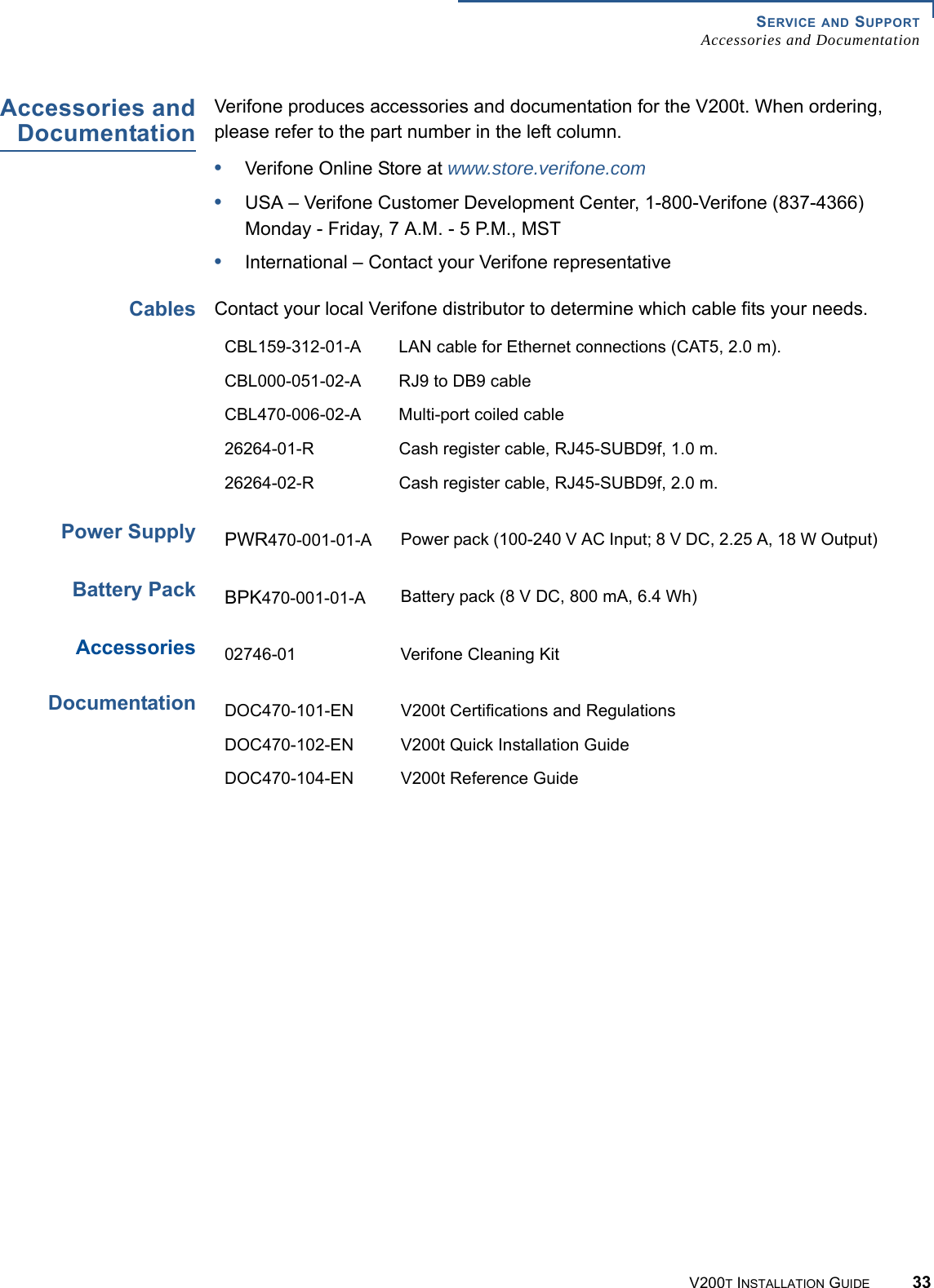
- 2. DOC470-003-EN-A_V200t_Installation_Guide
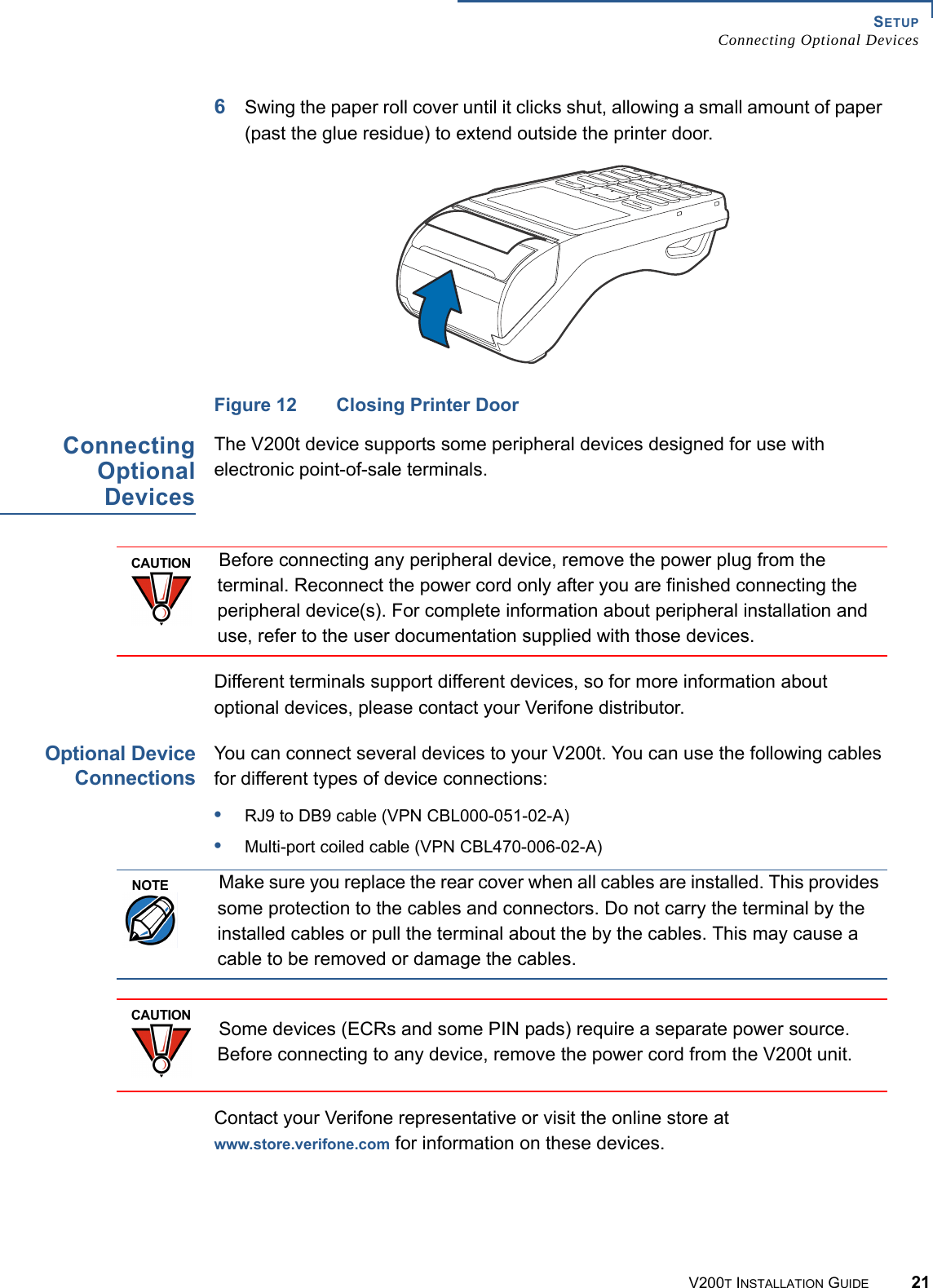
- 3. V200TPlus Label example
DOC470-003-EN-A_V200t_Installation_Guide