Verifone VX670GCR55I Point of Sale Terminal User Manual
VeriFone Inc Point of Sale Terminal
Verifone >
Users Manual
VeriFone Part Number 24003, Revision B
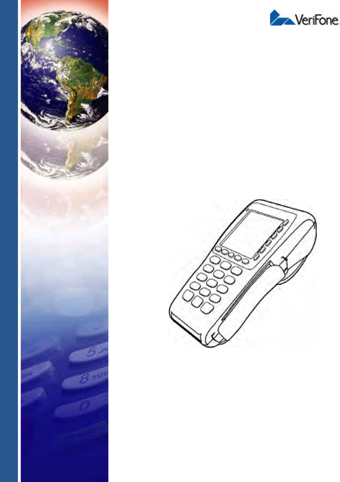
Vx670
Installation Guide

All rights reserved. No part of the contents of this document may be reproduced or transmitted in any form without the written
permission of VeriFone, Inc.
The information contained in this document is subject to change without notice. Although VeriFone has attempted to ensure the
accuracy of the contents of this document, this document may include errors or omissions. The examples and sample programs are
for illustration only and may not be suited for your purpose. You should verify the applicability of any example or sample program
before placing the software into productive use. This document, including without limitation the examples and software programs, is
supplied “As-Is.”
VeriFone, Inc.
2099 Gateway Place, Suite 600
San Jose, CA, 95110 USA
www.verifone.com
VeriFone Part Number 24003, Revision B
Vx670 Installation Guide
© 2007 VeriFone, Inc.
VeriFone, the VeriFone logo, Omni, VeriCentre, Verix, and ZonTalk are registered trademarks of VeriFone. Other brand names or
trademarks associated with VeriFone’s products and services are trademarks of VeriFone, Inc.
All other brand names and trademarks appearing in this manual are the property of their respective holders.
Comments? Please e-mail all comments on this document to your local VeriFone Support Team.
WARNING
Do not dispose of the Vx670 Li-ion smart battery in a fire. Li-ion batteries must be recycled or
disposed of properly. Do not dispose of Li-ion batteries in municipal waste sites.
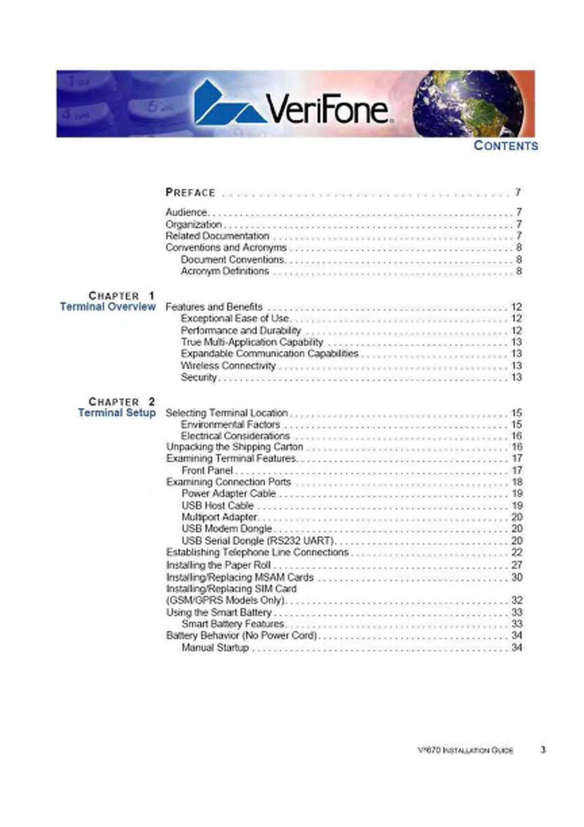

CONTENTS
VX670 INSTALLATION GUIDE 5
Printer Paper Jam . . . . . . . . . . . . . . . . . . . . . . . . . . . . . . . . . . . . . . . . . . . . . . . 55
Keypad Does Not Respond . . . . . . . . . . . . . . . . . . . . . . . . . . . . . . . . . . . . . . . . 56
Transactions Fail To Process. . . . . . . . . . . . . . . . . . . . . . . . . . . . . . . . . . . . . . . 56
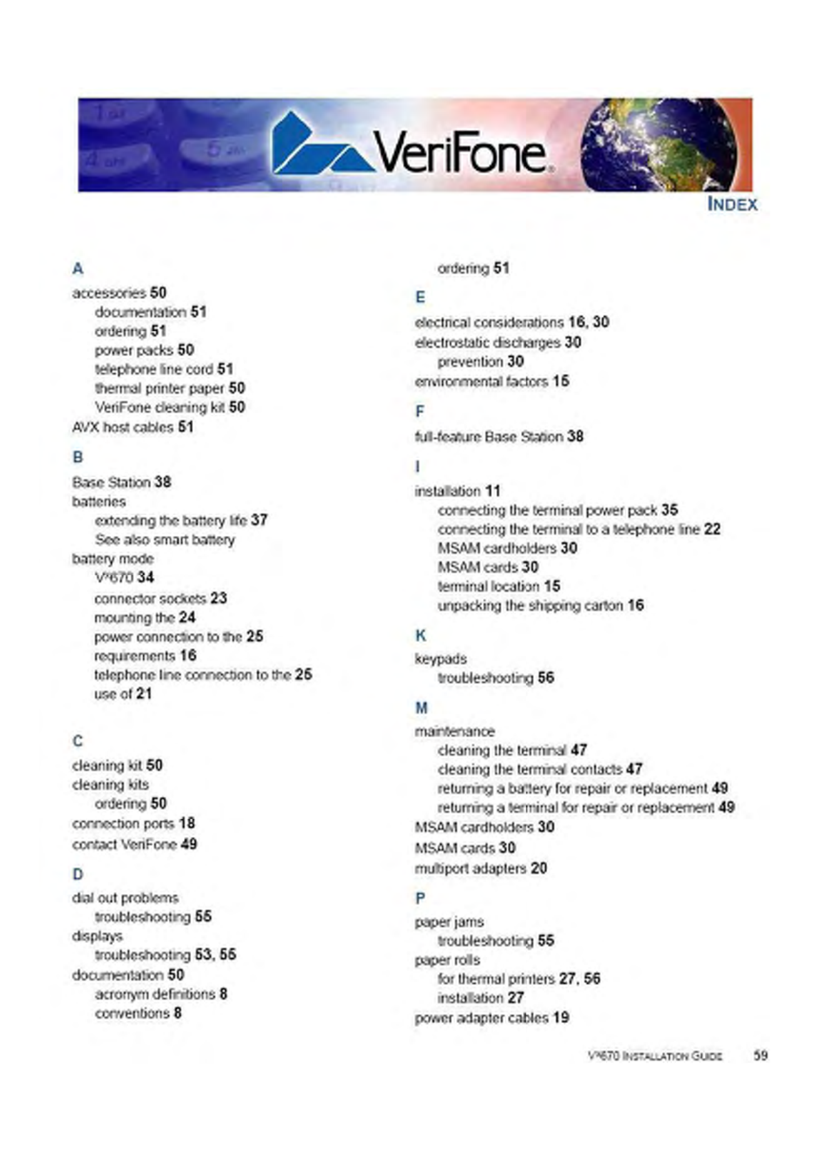
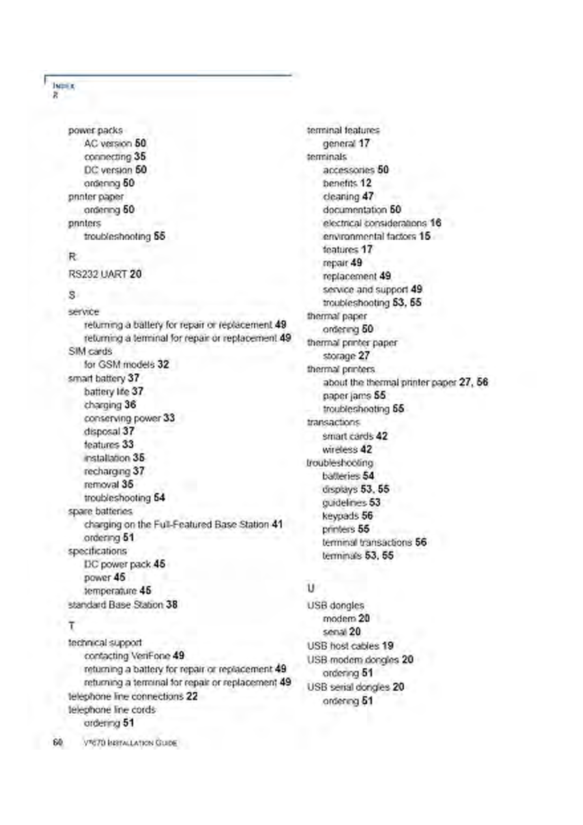
INDEX. . . . . . . . . . . . . . . . . . . . . . . . . . . . . . . . . . . . . . . . . 59

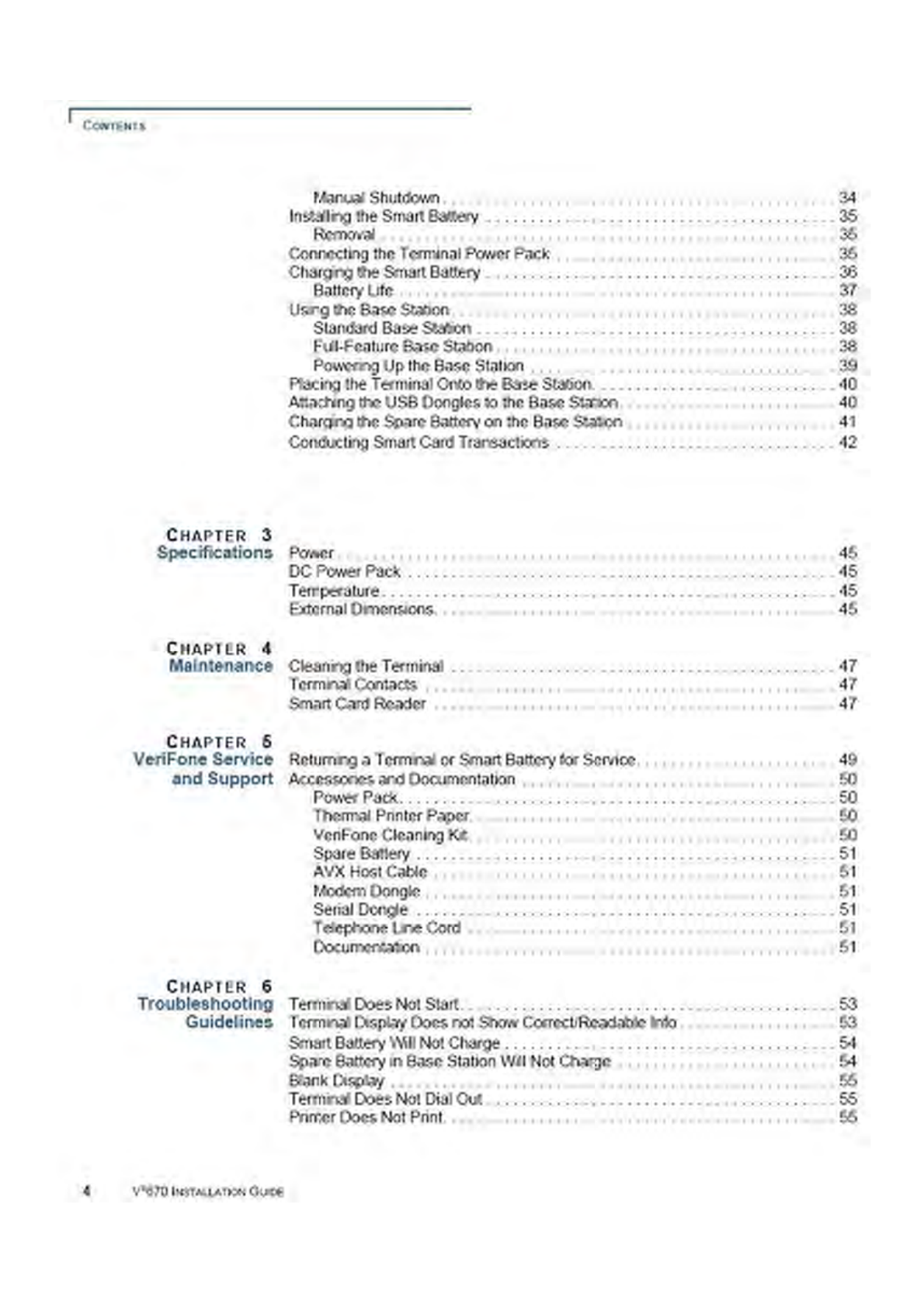
CONTENTS
6VX670 INSTALLATION GUIDE

PREFACE
Conventions and Acronyms
10 VX670 INSTALLATION GUIDE
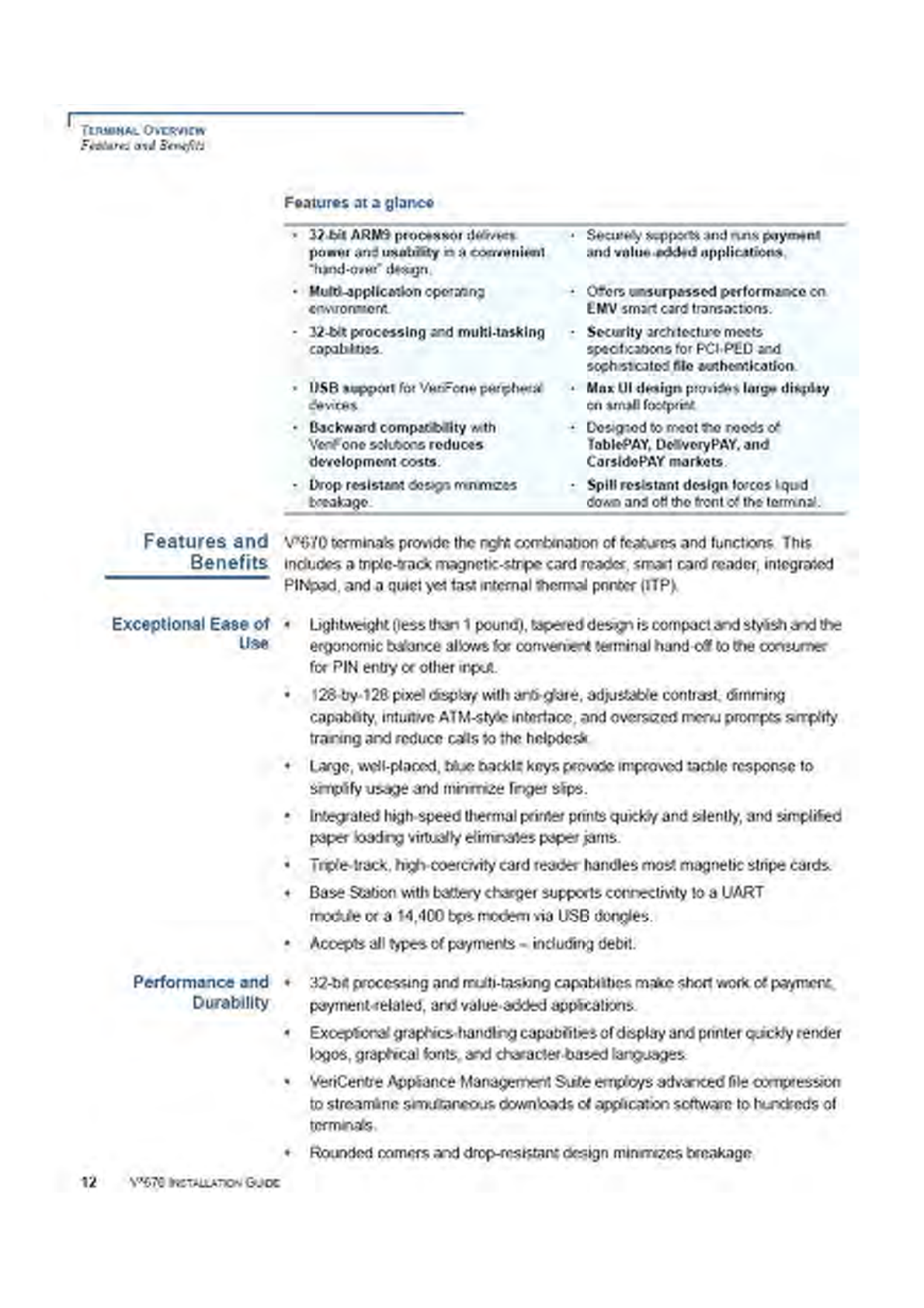
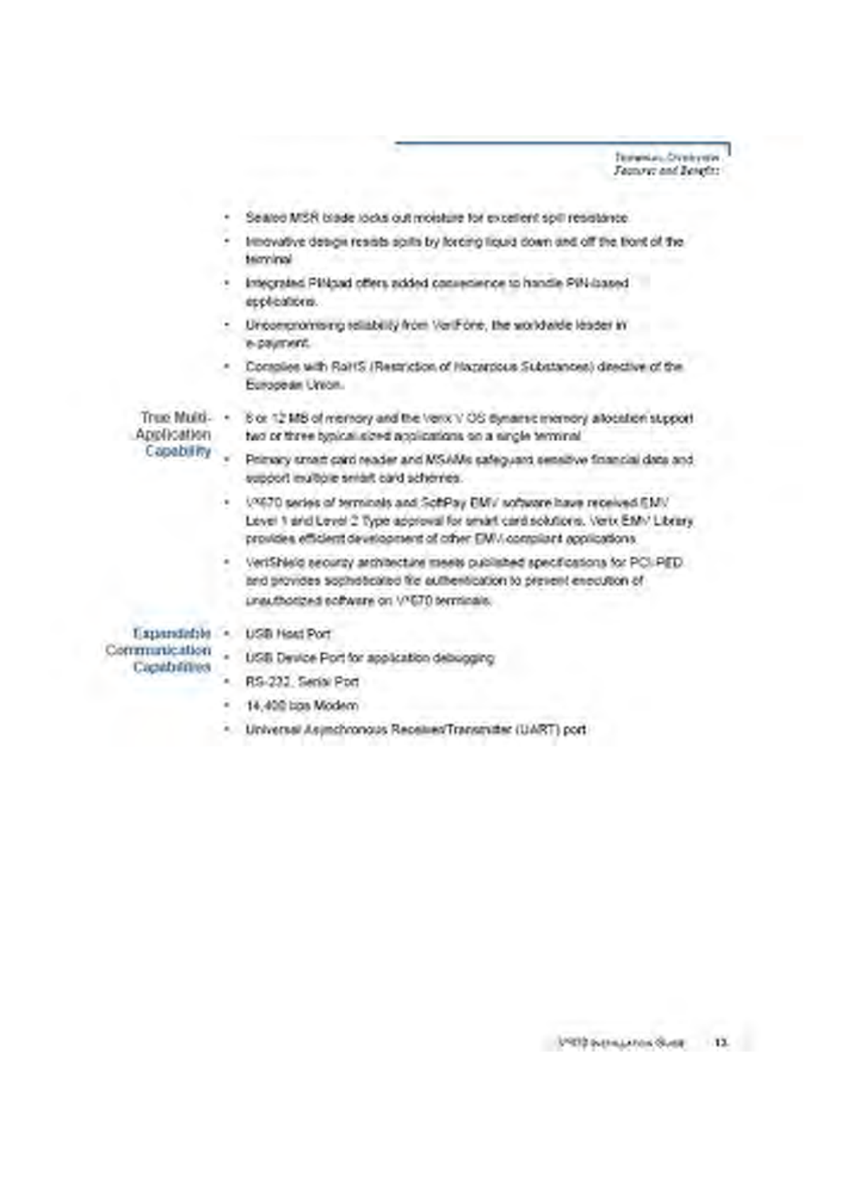

TERMINAL OVERVIEW
Features and Benefits
14 VX670 INSTALLATION GUIDE
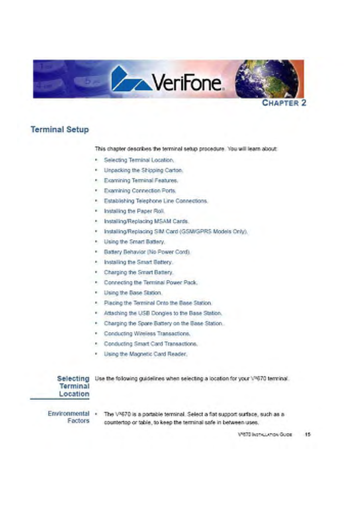
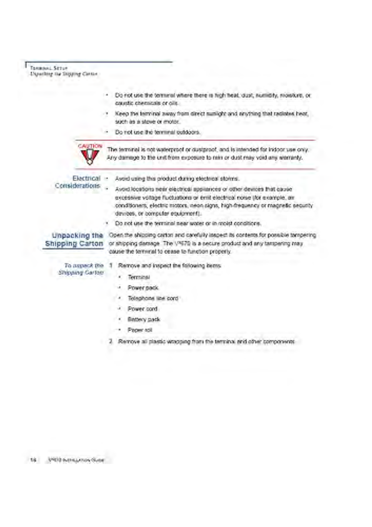
TERMINAL SETUP
Examining Terminal Features
VX670 INSTALLATION GUIDE 17
3Remove the clear protective film from the LCD screen.
4Save the shipping carton and packing material for future repacking or moving
the terminal.
Examining
Terminal
Features
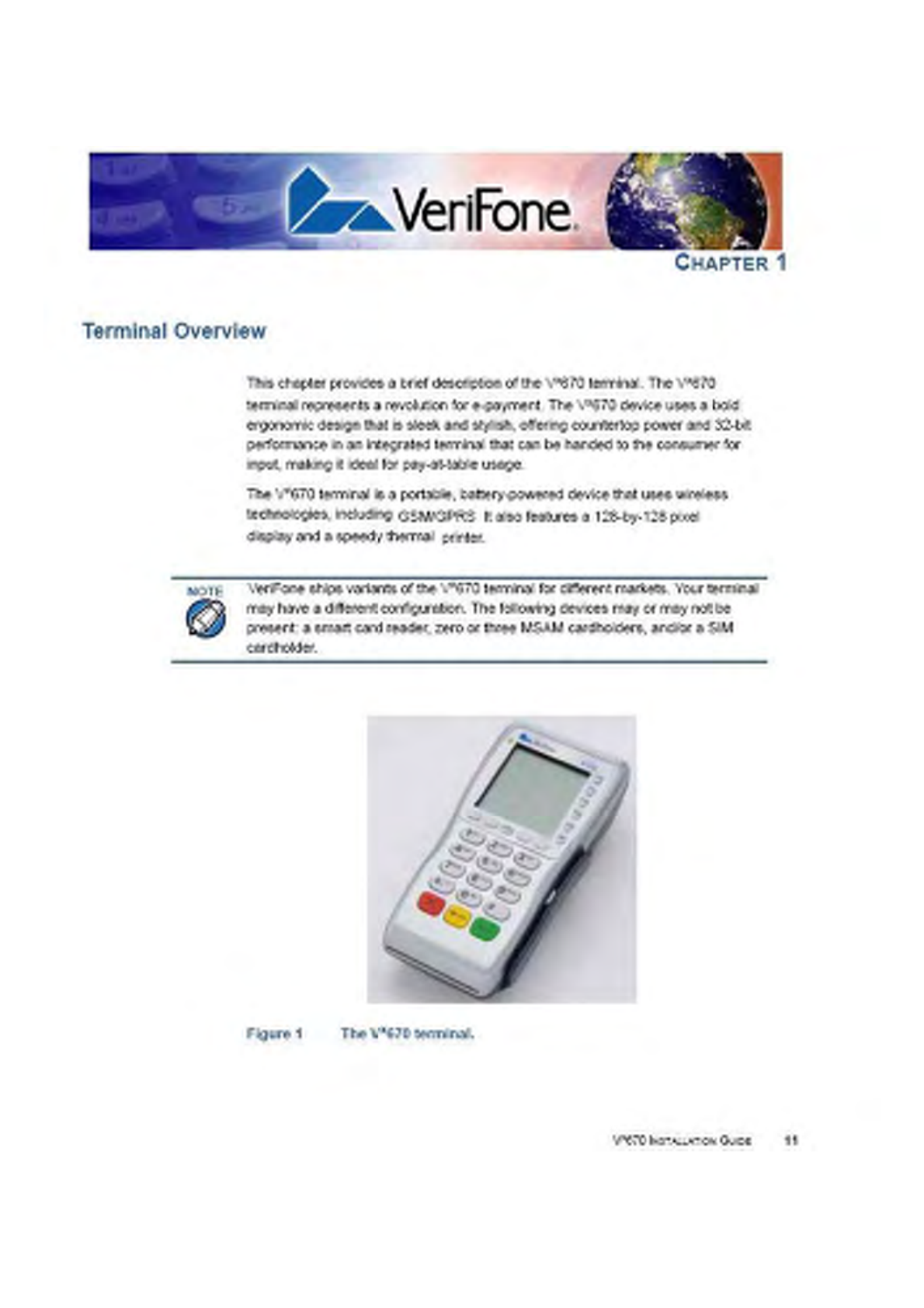
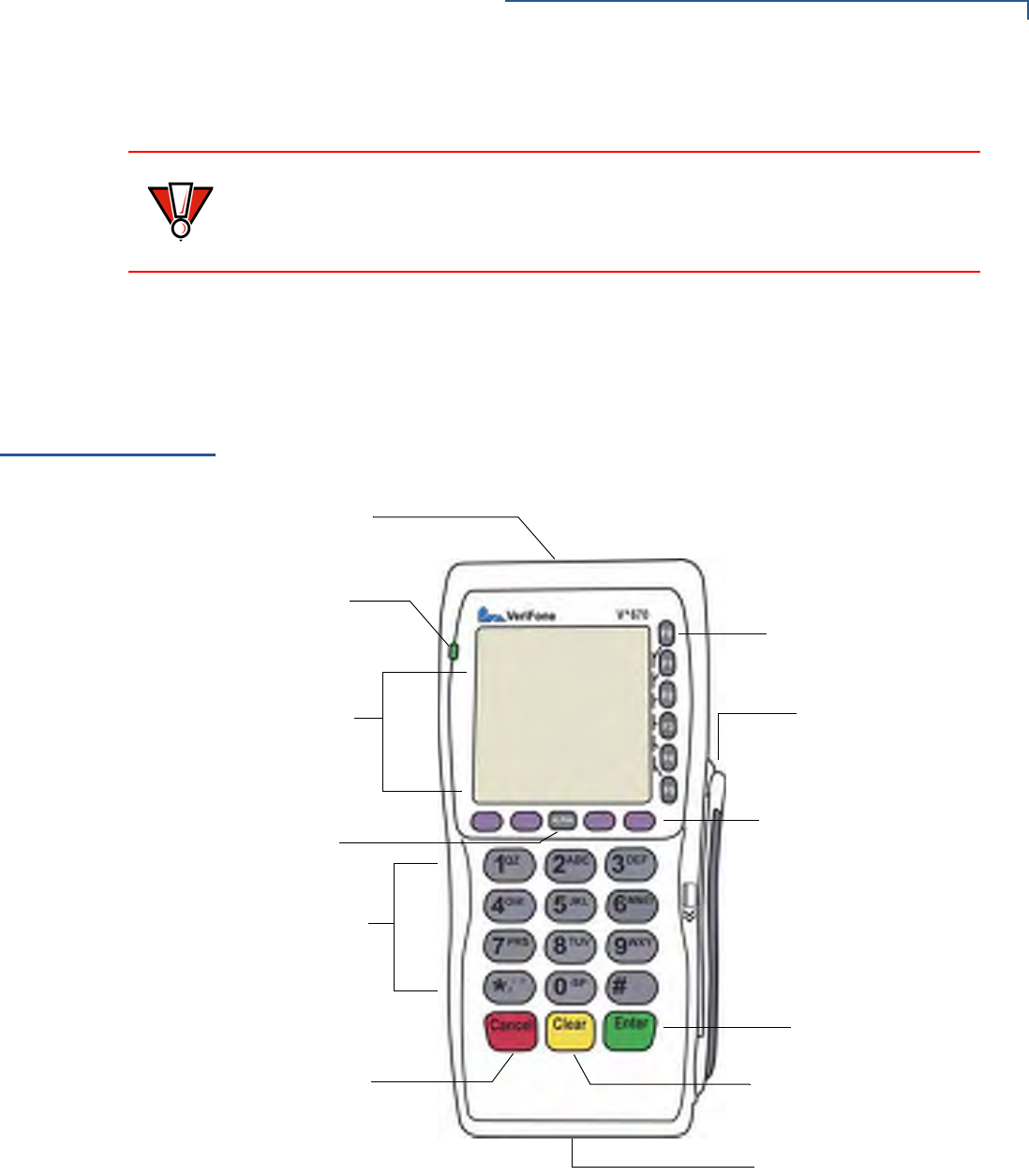
Before you continue the installation process, notice the features of the
Vx670 terminal (see Figure 2).
Figure 2 Vx670 Terminal Features (Front Panel)
Front Panel
The front panel includes the following features:
•A terminal display, backlit LCD screen.
•Five types of keys:
CAUTION
Do not use a terminal that has been damaged or tampered with. The
Vx670 terminal comes equipped with tamper-evident labels. If a label or
component appears damaged, please notify the shipping company and your
VeriFone representative or service provider immediately.
MAGNETIC CARD
TELEPHONE-STYLE
KEYPAD
CLEAR KEY
PROGRAMMABLE
ATM-STYLE FUNCTION
ALPHA KEY
SMART CARD READER
INDICATOR LED
INTERNAL THERMAL
PRINTER (AT THE BACK)
FUNCTION KEYS
KEYS
READER
CANCEL KEY
ENTER KEY
TERMINAL DISPLAY
TERMINAL SETUP
Examining Connection Ports
18 VX670 INSTALLATION GUIDE
aA 12-key, telephone-style keypad (keypads may vary in style).
bSix ATM-style function keys, labeled F0 to F5, to the right of the LCD
screen.
cFour programmable function keys above the keypad.
dThree color-coded function keys below the
keypad (icons at right; from left to right: CANCEL,
CLEAR, ENTER).
eAn ALPHA key centered at the top of the keypad.
•A magnetic card reader, built into the right side. Swipe the card using the
proper direction, with the magnetic stripe down and facing inward, toward the
keypad.
•A green indicator LED indicates power is ON.
•An internal thermal printer at the back of the terminal.
•A smart card reader, built into the front of the terminal. For directions on how
to use a smart card, see Conducting Smart Card Transactions.
•A SAM (security access module) compartment, built into the bottom of the
terminal. The Vx670 terminal contains MSAM cardholders to support multiple
stored-value card programs or other merchant card requirements.
Examining
Connection
Ports
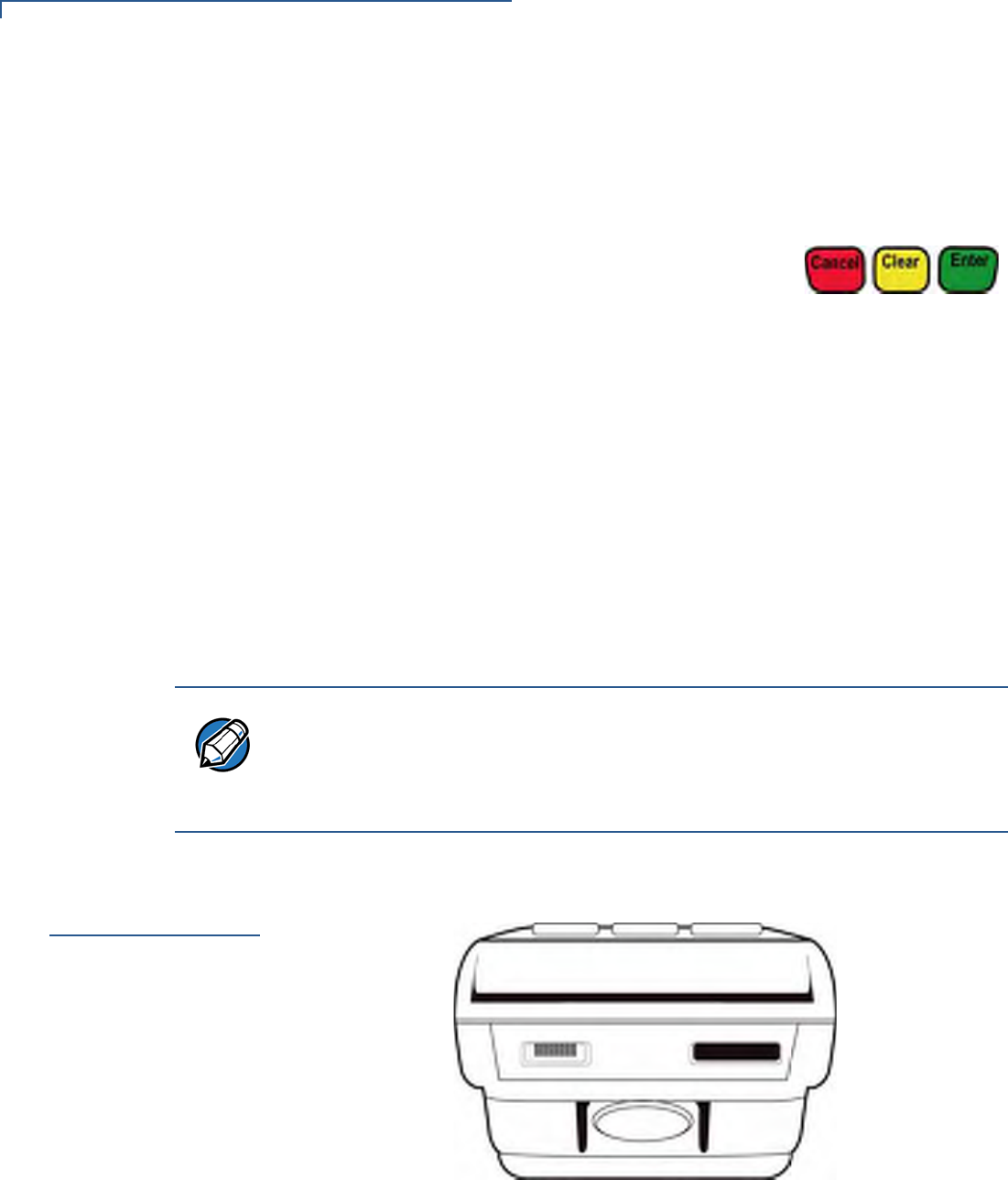
The Vx670 terminal has one primary port that supports different peripherals
through the use of various cables.
Figure 3 The Vx670 Primary Port (Bottom View)
NOTE
VeriFone ships variants of the Vx670 terminal for different markets. Your terminal
may have a different configuration. The following devices may or may not be
present: a smart card reader, or zero or three MSAM cardholders. However, the
basic processes described in this guide remain the same, regardless of terminal
configuration.
TERMINAL SETUP
Examining Connection Ports
VX670 INSTALLATION GUIDE 19
Power Adapter
Cable
Each Vx670 terminal comes with a power adapter cord (VPN 24224-01-R) that
completes the connection between the power pack and the terminal.
Figure 4 Power Adapter Cable Connection to a Vx670 Terminal
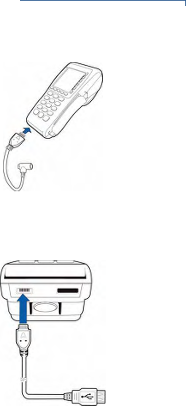
USB Host Cable
A 2-Wire USB Host port (VPN 24223-01-R) for external peripherals. A connector
adaptor provides for standard USB host connection for the Modem Dongle or the
RS232 UART Dongle.
Figure 5 USB Host Cable Connection to a Vx670 Terminal
TERMINAL SETUP
Examining Connection Ports
20 VX670 INSTALLATION GUIDE
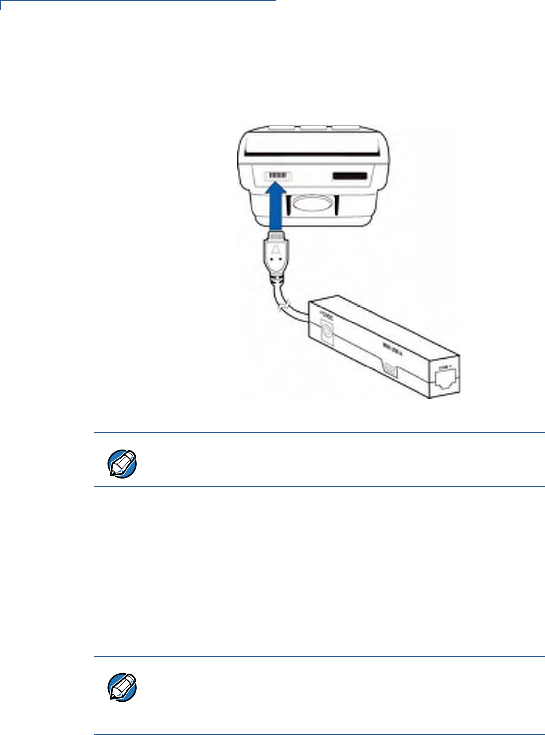
Multiport Adapter
A multiport adapter (VPN 24799-01-R) that provides connectivity for power, USB
Host, USB Device, and COM1 (RS232 UART). This cable is used only for
deployment or development purposes.
Figure 6 Multiport Adapter Connection to a Vx670 Terminal
USB Modem Dongle
A modem in the form of a USB Modem Dongle may be provided with the Vx670
terminal. The M267-D10-00 USB Modem Dongle provides communication via a
telephone line at speeds of up to 14,400 bps. It can also be connected to the full-
feature Base Station when the terminal is in the station (see Attaching the USB
Dongles to the Base Station).
USB Serial Dongle
(RS232 UART)
The USB Serial Dongle (VPN M267-D01-00) may be provided with the Vx670
terminal. It is designed to accommodate the RJ45 connector. The USB Serial
Dongle can also be connected to the full-feature Base Station when the terminal is
placed in the station (see Attaching the USB Dongles to the Base Station).
NOTE
Other cables are available for development purposes. Check with your local
VeriFone representative for further information.
NOTE
A Base Station may be provided with the Vx670 terminal. A full-feature Base
Station has two USB host ports for external dongles as well as a battery charger
slot for charging an extra lithium-ion battery pack. A standard Base Station does
not have any USB ports and is capable of charging the terminal only and not the
extra battery pack.
TERMINAL SETUP
Establishing Telephone Line Connections
22 VX670 INSTALLATION GUIDE
Establishing
Telephone Line
Connections
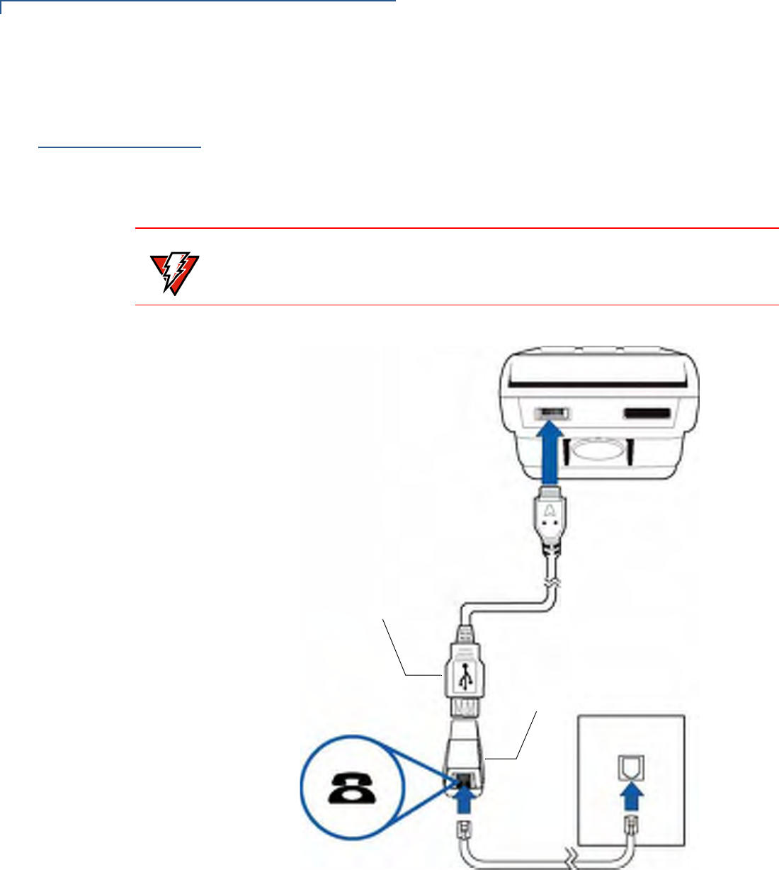
To connect a telephone line:
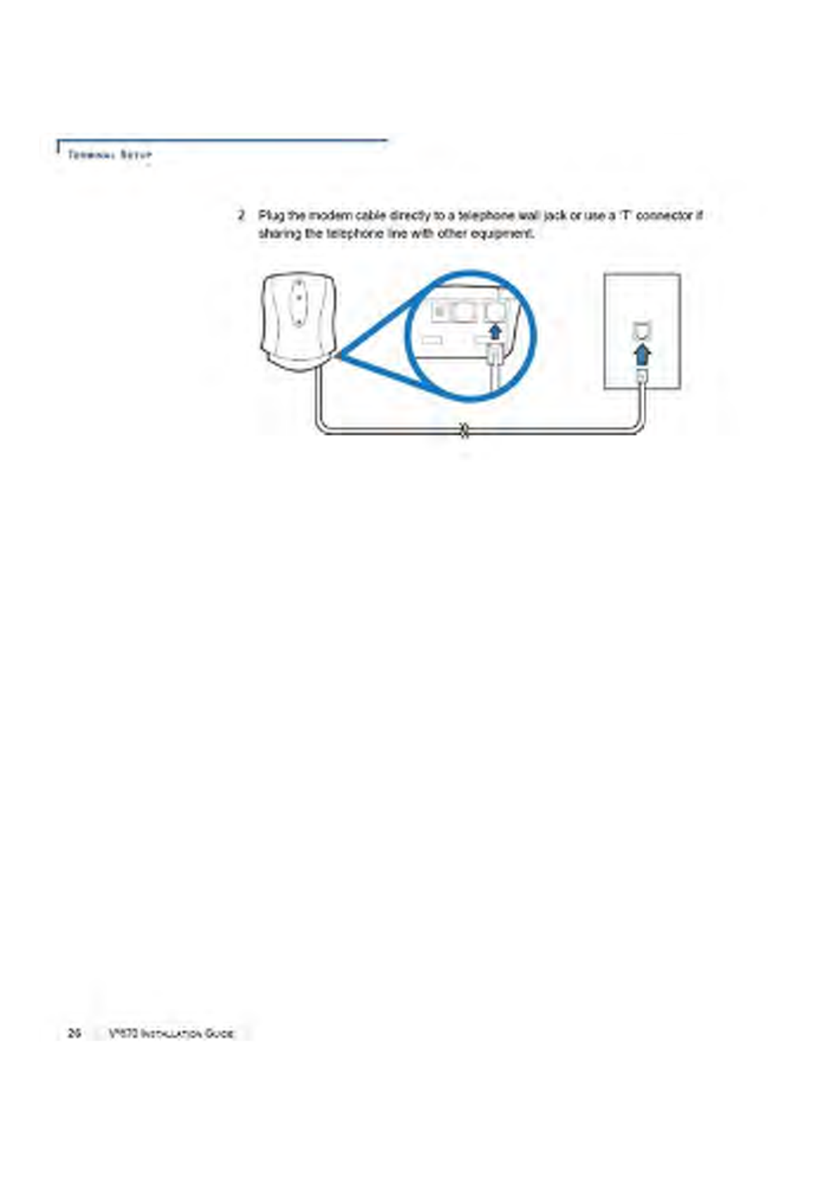
1Connect one end of the telephone cord to the USB Modem Dongle.
2Connect the USB Modem Dongle to the terminal using the AVX Connector
(VPN 24223-01-R).
3Route the other end of the telephone cord directly to a telephone wall jack.
Figure 8 Vx670 USB Modem Dongle Connection
WARNING
To reduce the risk of fire, use only No. 26 AWG or larger UL Listed or CSA
Certified Telecommunication Line Cord.
USB HOST CABLE
USB MODEM DONGLE

TERMINAL SETUP
Installing the Paper Roll
VX670 INSTALLATION GUIDE 27
Installing the
Paper Roll
A fast, quiet thermal printer is built into the Vx670 terminal. Before you can
process transactions that require a receipt or record, you must install a roll of
thermal-sensitive paper in the printer.
The ITP uses a roll of single-ply, thermal-sensitive paper 57 millimeters (2.24
inches) wide and 38 millimeters in diameter. A pink out-of-paper indicator line
appears on the edge of the paper approximately 18 inches before the end of the
roll. After this line appears, there is enough paper remaining on the roll to
conclude at least one transaction.
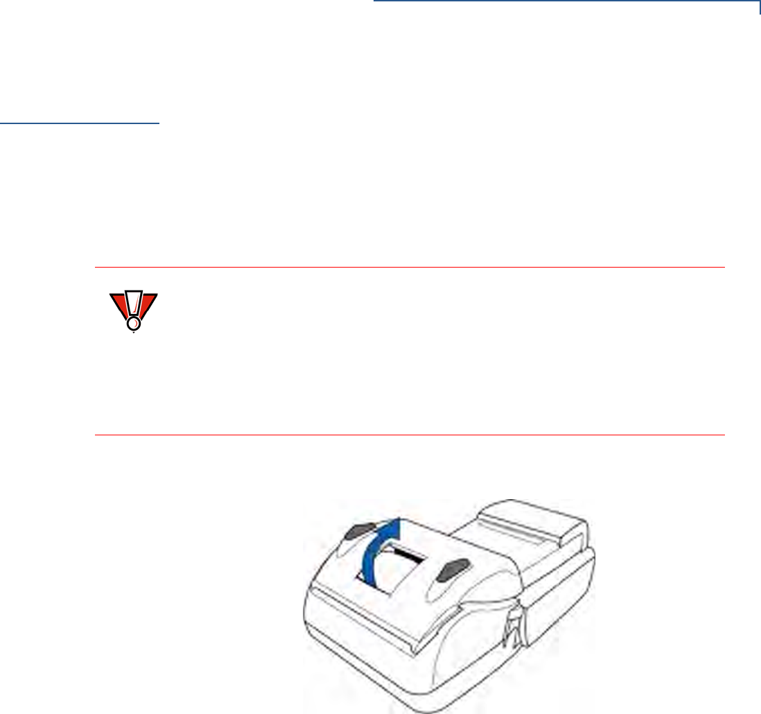
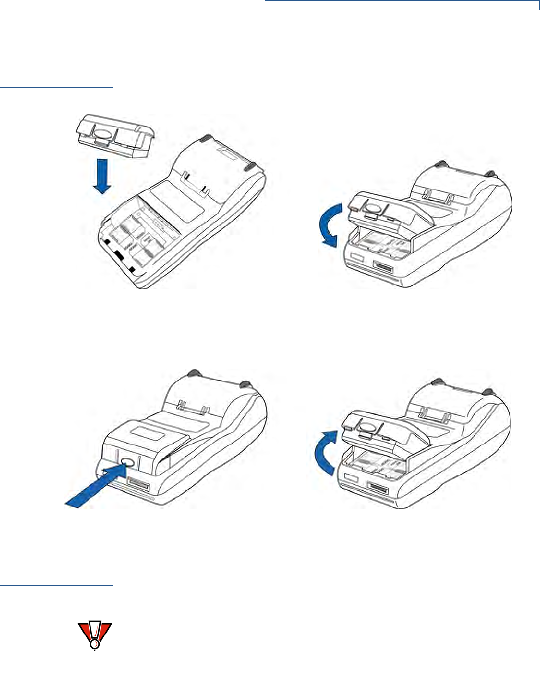
To Install a Paper Roll 1Gently pull the latch located on the bottom of the terminal to unlock the paper
roll cover.
Figure 13 Unlocking the Printer Cover
CAUTION
Poor-quality paper can jam the printer and create excessive paper dust. To order
high-quality VeriFone paper, refer to Accessories and Documentation.
Store thermal paper in a dry, dark area. Handle thermal paper carefully: impact,
friction, temperature, humidity, and oils affect the color and storage
characteristics of the paper.
Never load a roll of paper with folds, wrinkles, tears, or holes at the edges in the
print area.
TERMINAL SETUP
Installing the Paper Roll
28 VX670 INSTALLATION GUIDE
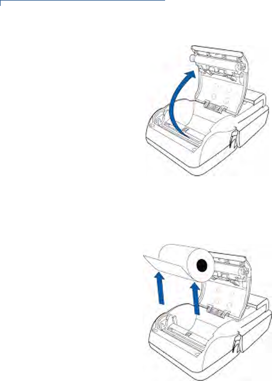
2Lift the printer cover up and back.
Figure 14 Opening the Printer Cover
3Remove any partial roll of paper in the printer tray by lifting it up (see Figure
15).
4Loosen the glued leading edge of the paper or remove the protective strip
from the new roll of paper. Unwind the paper roll past any glue residue.
Figure 15 Removing Partial Paper Roll
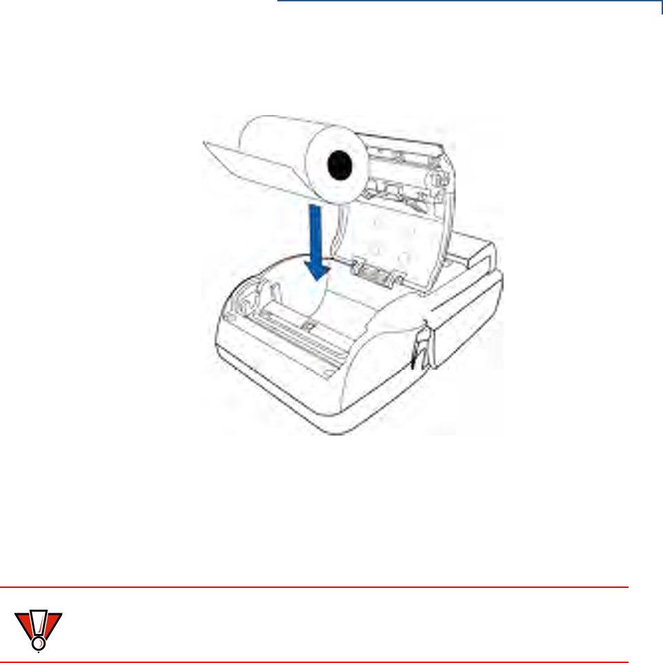
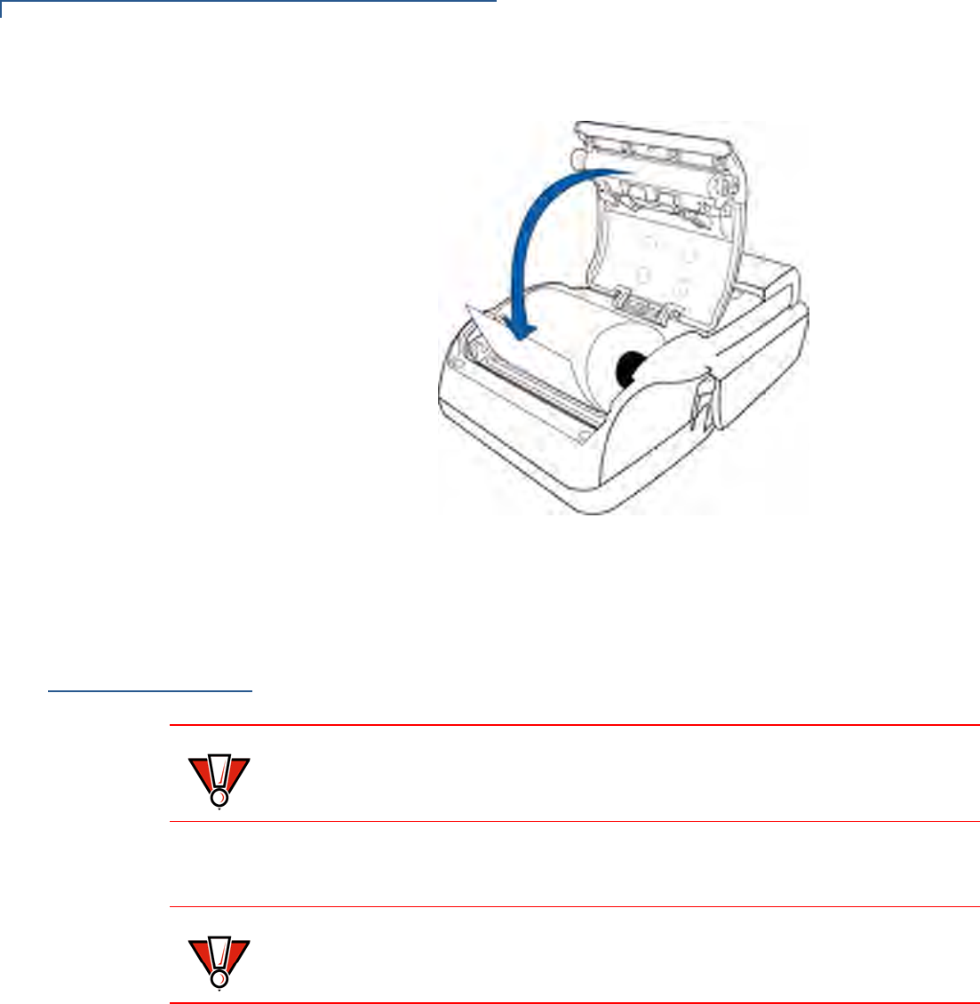
5Hold the roll so the paper feeds from the bottom of the roll when the terminal is
inverted (see Figure 16).
TERMINAL SETUP
Installing the Paper Roll
VX670 INSTALLATION GUIDE 29
6Drop the paper roll into the printer tray.
Figure 16 Loading Paper Roll
7Pull paper up past the glue residue on the paper roll.
8Close the paper roll cover by gently pressing directly on the cover until it clicks
shut, allowing a small amount of paper past the glue residue to extend outside
the printer door.
CAUTION
To prevent damaging the print roller, always gently press down on the paper roll
cover to close it.
TERMINAL SETUP
Installing/Replacing MSAM Cards
30 VX670 INSTALLATION GUIDE
Figure 17 Closing Paper Roll Cover
9Tear the paper off against the serrated plastic strip in the printer.
Installing/
Replacing MSAM
Cards
When you first receive your Vx670 terminal, you may need to install one or more
MSAM cards or you may need to replace old cards.
To Install/Replace
MSAMs 1Power off the terminal.
2Place the terminal upside down on a soft, clean surface to protect the display
from scratches.
CAUTION
Observe standard precautions when handling electrostatically sensitive devices.
Electrostatic discharges can damage this equipment. VeriFone recommends
using a grounded anti-static wrist strap.
CAUTION
It is very important that the terminal is powered off before removing the battery.
TERMINAL SETUP
Installing/Replacing MSAM Cards
VX670 INSTALLATION GUIDE 31
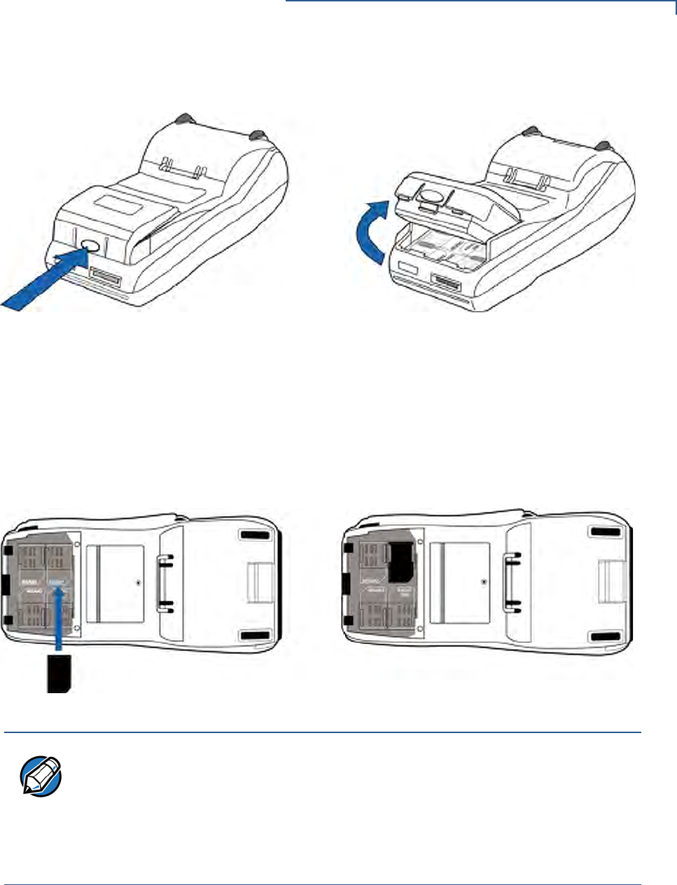
3Remove the battery.
Figure 18 Removing the Smart Battery
4After removing the battery, the MSAM compartments are exposed.
5Remove any previously installed MSAM card by sliding the card from the
MSAM cardholder.
6Install an MSAM card by aligning the card and carefully sliding it within the
guides on the cover until it is fully inserted (see Figure 19). The MSAM card
holders are labeled MSAM1, MSAM2, and MSAM3.
Figure 19 Installing MSAM Card
7Install the battery (see Figure 22).
NOTE
Before inserting the MSAM card, position it as shown in Figure 19, with the card’s
gold contacts facing the smart card reader end of the terminal. The cardholder
connector base has a set of contacts and a notch on one corner to ensure the
MSAM card is positioned correctly. The MSAM card has a notch on one corner to
ensure that it fits into the connector base in only one way. The MSAM
compartment door will not close properly if the MSAM cards are installed
incorrectly.
TERMINAL SETUP
Installing/Replacing SIM Card (GSM/GPRS Models Only)
32 VX670 INSTALLATION GUIDE
Installing/
Replacing SIM
Card
(GSM/GPRS
Models Only)
The Vx670 terminal supports the installation of a SIM (Subscriber Identity Module)
card. Use the following procedure to replace or install a SIM card.
1Place the terminal upside down on a soft, clean surface to protect the lens
from scratches.
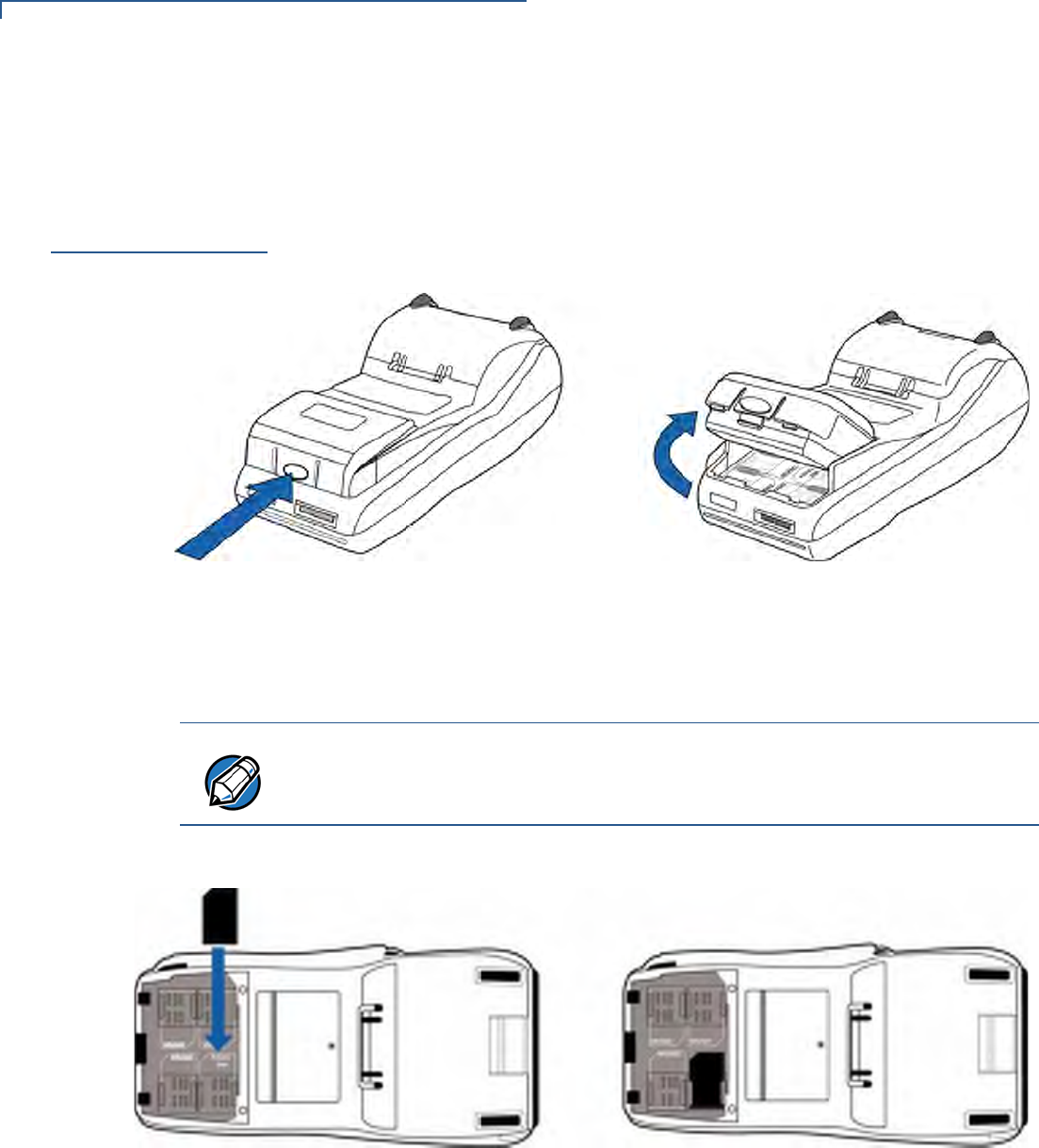
2Remove the battery.
Figure 20 Removing the Smart Battery
3After removing the battery, the SIM compartment is exposed. The SIM card
holder is labeled RADIO SIM.
4Insert the SIM into the cardholder.
Figure 21 Inserting SIM Card
5Install the battery (see Figure 22).
NOTE
There is only one SIM slot, but there are multiple SAM slots. Make sure you insert
the SIM card into the SIM slot, as shown in Figure 21.

TERMINAL SETUP
Using the Smart Battery
VX670 INSTALLATION GUIDE 33
Using the Smart
Battery
The Vx670 terminal uses an Li-ion smart battery (see Accessories and
Documentation for ordering information). The internal logic of the smart battery
prevents both overcharging and undercharging (a fault condition in which the
battery level goes well below the minimum acceptable charge and the battery
becomes unusable).
Smart Battery
Features
The following are features of the smart battery:
•Two Li-ion cells
•A fuel gauge module that:
•monitors state of charge (voltage and percentage of capacity),
•communicates with the terminal (charge parameters and status),
•determines full charge capacity (on charge cycle and uninterrupted
discharge cycle), and
•automatically shuts down when cell voltage is extremely low.
•A safety circuit that:
•prevents cell damage from overcharge, over-discharge, or overheating,
and
•activates when the battery is left in an unused terminal for extended
periods.
NOTE
The Vx670 terminal will operate on battery power or on power pack power. The
smart battery charger in the terminal will be active whenever the power pack is
connected.
NOTE
•Lithium-ion batteries are not affected by shallow charging. Furthermore, when
the terminal has no external power source or smart battery, the coin cell
battery provides power to the security circuit.
•Uninstalling the battery and unplugging the terminal power pack reduce the
life of the coin cell battery, which does not recharge and must be replaced if
drained.
•Conserve battery power by turning the Vx670 terminal off when not in use. If
the terminal is not to be used for an extended period of time, keep the Lithium-
ion battery inserted in the terminal, and power up the terminal periodically to
check the battery charge. Do not let the battery charge fall below 10% for
extended periods of time as this may permanently diminish the battery
capacity. Recharge the battery by attaching the power cord to the terminal and
plugging the power pack into a wall outlet.
TERMINAL SETUP
Battery Behavior (No Power Cord)
34 VX670 INSTALLATION GUIDE
Battery Behavior
(No Power Cord)
If you connect the Vx670 to a non-battery power source, the terminal shifts to
corded power mode and starts up automatically, regardless of the battery charge
state.
Manual Startup
Hold the green key down for about 4 seconds until the terminal displays the
startup screen.
When the terminal has power, the terminal lights are activated and the green LED
indicator remains lit.
Manual Shutdown
Hold the red key down for about 4 seconds until the terminal displays the
shutdown verification screen. Keep holding the red key until the Vx670 terminal
shuts down.
NOTE
The 4-second power-up delay is for preventing terminal startup if the green key is
accidentally held down. The time required to hold the green key down to power up
the terminal is configurable (for more information, see the Vx670 Reference
Manual – VPN 24004).
NOTE
If an application is loaded in the terminal, it starts after the initial VeriFone
copyright screen and usually displays a unique copyright screen. If no application
is loaded in the terminal, DOWNLOAD NEEDED appears on screen after the initial
VeriFone copyright screen.
NOTE
•The 4-second shutdown delay is for preventing terminal shutdown if the red
key is accidentally held down. The time required to hold the red key down to
shut down the terminal is configurable (for more information, see the Vx670
Reference Manual – VPN 24004).
•When the terminal has no power, the screen is blank and the green LED
indicator is not lit.
TERMINAL SETUP
Installing the Smart Battery
VX670 INSTALLATION GUIDE 35
Installing the
Smart Battery
The Vx670 smart battery fits in a slot on the back of the Vx670 terminal, as shown
in Figure 22. The locking tab clicks when the battery is in place. The slot is keyed,
so that there is only one way to insert the battery.
Figure 22 Installing the Smart Battery
Removal
To remove the Vx670 smart battery, press the locking tab and pull the smart
battery from its slot.
Figure 23 Detaching the Smart Battery from the Vx670 Terminal
Connecting the
Terminal Power
Pack
When you have finished installing the smart battery, you are ready to connect the
Vx670 terminal to the provided power source for initial charging.
CAUTION
Using an incorrectly rated power supply may damage the terminal or cause it not
to work as specified. Before troubleshooting, ensure that the power supply being
used to power the terminal matches the requirements specified on the bottom of
the terminal. (See Chapter 3, Specifications, for detailed power supply
specifications.) Obtain the appropriately rated power supply before continuing
with troubleshooting.
TERMINAL SETUP
Charging the Smart Battery
36 VX670 INSTALLATION GUIDE
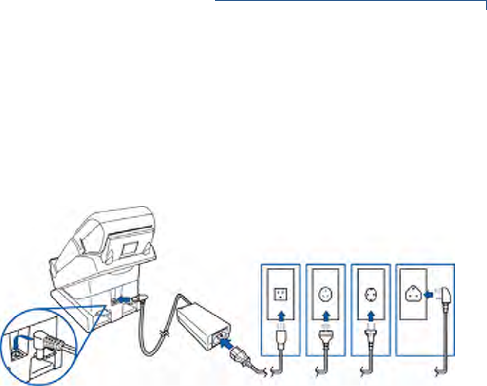
The Vx670 unit comes with a universal input power pack capable of operating
from voltages of 100VAC to 240VAC.
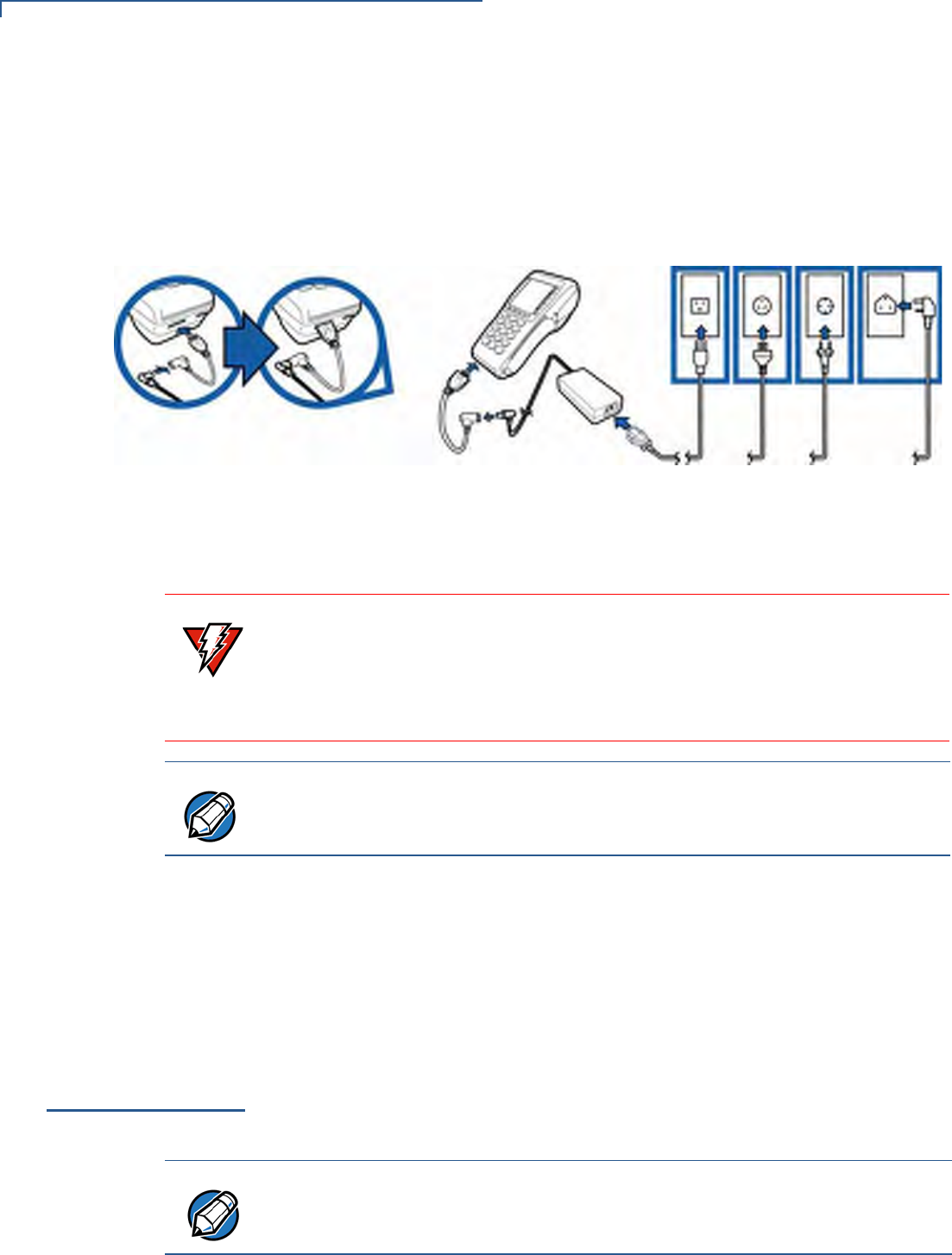
To Connect the
Terminal Power Pack 1Insert the round barrel connector into the power port in the connector, as
shown in Figure 24.
Figure 24 Vx670 Power Pack Connection
2Insert the AC power cord into the power pack.
3Plug the AC power cord into a wall outlet or powered surge protector.
When the terminal has power, the terminal lights are activated and the LED
indicator remains lit.
If an application is loaded in the terminal, it starts after the initial VeriFone
copyright screen and usually displays a unique copyright screen. If no application
is loaded in the terminal, DOWNLOAD NEEDED appears on screen after the initial
VeriFone copyright screen.
Charging the
Smart Battery
After unpacking your Vx670 terminal, install the battery and connect the power
pack to the unit for 6 hours or until fully charged.
WARNING
Do not plug the power pack into an outdoor outlet or operate the terminal
outdoors.
During a transaction, disconnecting the power by removing the battery or
unplugging the terminal from a wall power while at very low battery charge may
cause transaction data files not yet stored in the terminal memory to be lost.
NOTE
To protect against possible damage caused by lightning strikes and electrical
surges, consider installing a power surge protector.
NOTE
The Vx670 terminal’s smart battery is also charged when the terminal is in the
Base Station. For more information, see Placing the Terminal Onto the Base
Station.
TERMINAL SETUP
Charging the Smart Battery
VX670 INSTALLATION GUIDE 37
The smart battery has a safety circuit to protect the Li-ion cells from overcharging
and over-discharging. If the battery is over-discharged, the safety circuit shuts
down the battery. The battery must then be recharged to restore operation.
Battery Life
The Vx670 smart battery can be charged and discharged hundreds of times, but
will eventually wear out. When operating times are noticeably shorter than usual,
it is time to buy a new battery (see Accessories and Documentation for ordering
information).
NOTE
The Vx670 terminal automatically shuts off when the smart battery reaches the
critically low charge state. If this occurs, the smart battery must be recharged for a
minimum of 1/2 hour before it can power the terminal. It may take several
recharge attempts to reset the safety circuit when charging a smart battery that
has been discharged below this critical state.
WARNING
Do not dispose of batteries in a fire. Li-ion batteries must be recycled
or disposed of properly. Do not dispose of Li-ion batteries in municipal
waste sites.
TERMINAL SETUP
Using the Base Station
38 VX670 INSTALLATION GUIDE
Using the Base
Station
The primary purpose of the Base Station is to charge the terminal battery and
provide a docking station for the terminal after being used in pay-at-table
environments. The Base Station can be positioned on a countertop or mounted to
the wall.
There are two types of Base Stations, the standard model and the full-feature
model.
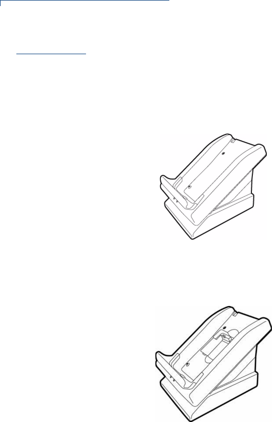
Standard Base
Station
The standard Base Station can charge the Vx670 terminal. However, it does not
have any external ports and has a single LCD to indicate power status.
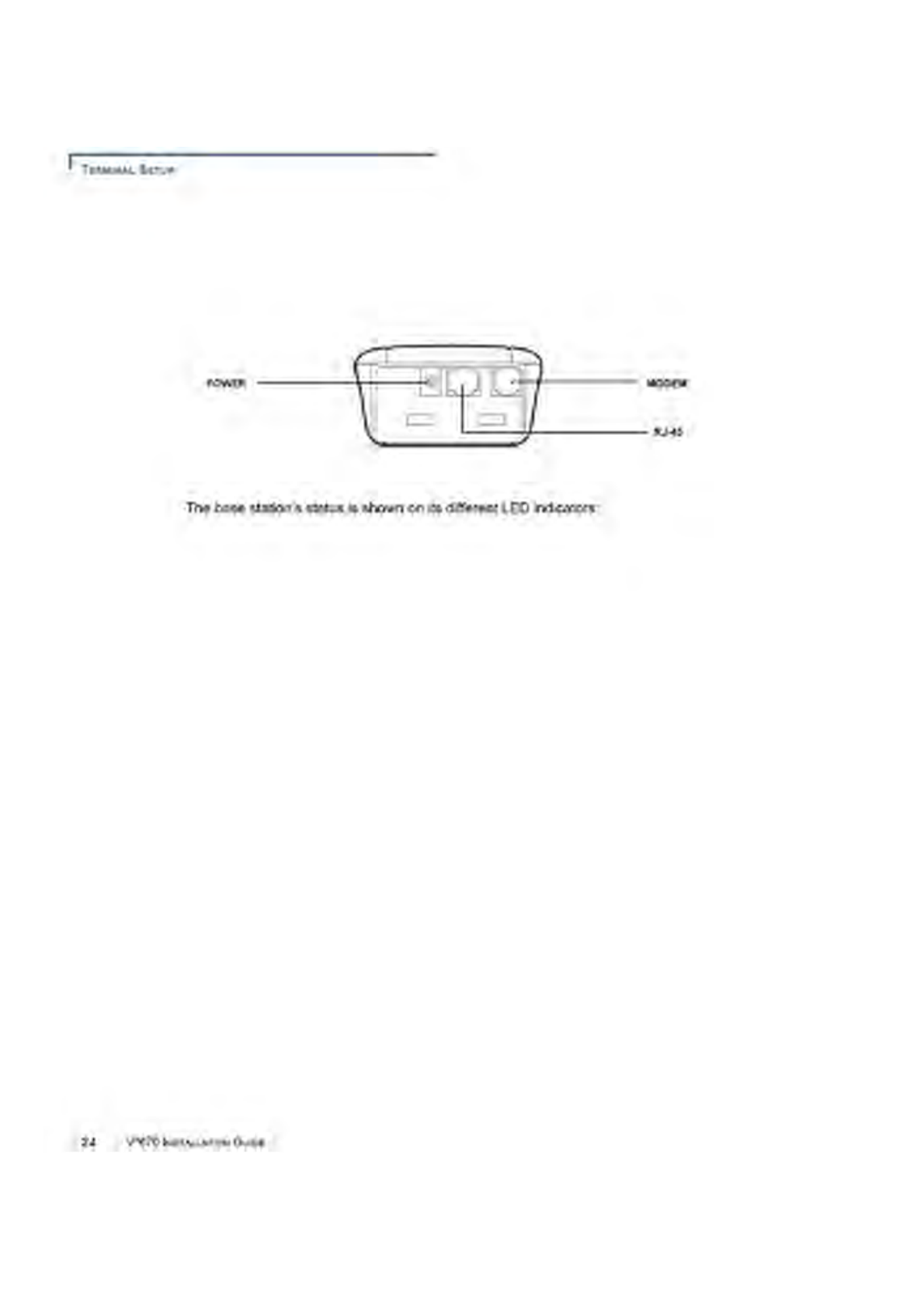
Figure 25 The Vx670 Standard Base Station
Full-Feature Base
Station
The full-feature Base Station can charge the Vx670 terminal while charging an
extra battery pack. In addition, it has two USB ports for external dongles, together
with one LED for power indication and another LED for the charger status.
Figure 26 The Vx670 Full-Feature Base Station
TERMINAL SETUP
Using the Base Station
VX670 INSTALLATION GUIDE 39
For more information on charging the spare battery on the full-feature Base
Station and connecting external dongles to the USB ports, see Charging the
Spare Battery on the Base Station and Attaching the USB Dongles to the Base
Station.
Powering Up the
Base Station
Use the procedure in this section to connect the Vx670 Base Station to a power
source.
1Insert the round barrel connector of the power pack into the power port at the
back of the Base Station.
Figure 27 Connecting the Base Station to a Power Source
2Insert the AC power cord into the power pack.
3Plug the AC power cord into a wall outlet or power surge protector.
4Confirm that the Base Station is powered up as indicated by the solid green
LED.
TERMINAL SETUP
Placing the Terminal Onto the Base Station
40 VX670 INSTALLATION GUIDE
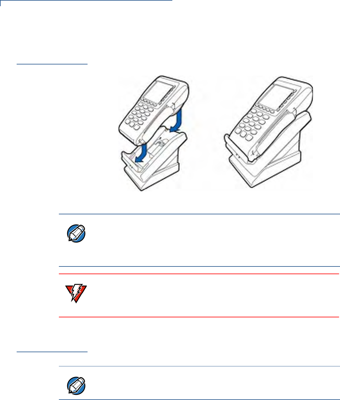
Placing the
Terminal Onto
the Base Station
The Vx670 terminal can be placed on the Base Station when not in use for
continuous charging of its battery. External peripherals can also be attached to
the terminal via USB dongles while it is on the Base Station (see Attaching the
USB Dongles to the Base Station).
Figure 28 Placing the Vx670 onto the Base Station
Attaching the
USB Dongles to
the Base Station
While the Vx670 terminal is resting on the Base Station, you can drive external
peripherals through the use of USB dongles. Only one Modem Dongle and one
Serial Dongle can be connected to the Base Station. A second Modem Dongle or
a second Serial Dongle will be ignored by the terminal.
NOTE
The full-feature Base Station can also charge a spare battery while it charges the
battery attached to the terminal (see Charging the Spare Battery on the Base
Station).
To protect against possible damage caused by lightning strikes and electrical
surges, consider installing a power surge protector.
WARNING
Do not plug the power pack into an outdoor outlet or operate the terminal
outdoors.
Disconnecting the power during a transaction may cause transaction data files
not yet stored in terminal memory to be lost.
NOTE
The full-feature Base Station has USB ports for two external dongles. The
standard Base Station does not have USB ports.
TERMINAL SETUP
Charging the Spare Battery on the Base Station
VX670 INSTALLATION GUIDE 41
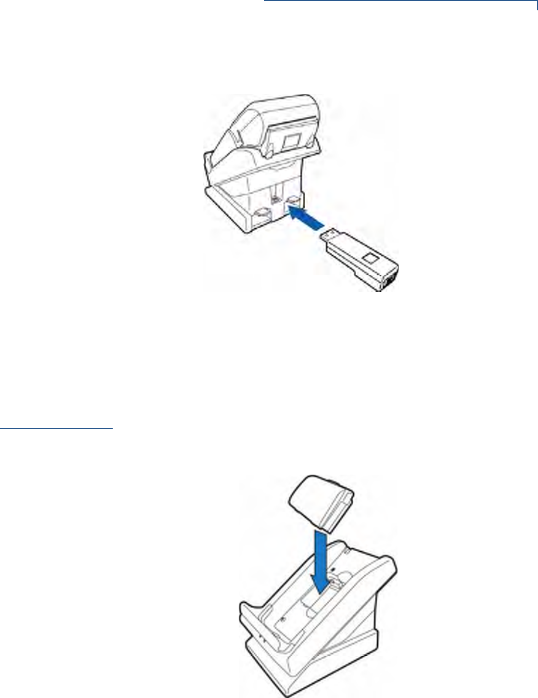
1Insert the USB dongle into the USB port located at the back of the Base
Station.
Figure 29 Inserting External Dongle Into USB Port
2After inserting the external dongle into the USB port, place the Vx670 terminal
onto the Base Station (see Powering Up the Base Station).
3Connect the peripheral to the external dongle.
Charging the
Spare Battery on
the Base Station
The full-feature Base Station can charge the Vx670 terminal while charging an
extra battery pack.
1Connect the Base Station to a power source (see Powering Up the Base
Station)
2Place the spare battery pack onto the Base Station as shown in Figure 30.
Figure 30 Putting Spare Battery Pack Into the Base Station
TERMINAL SETUP
Conducting Wireless Transactions
42 VX670 INSTALLATION GUIDE
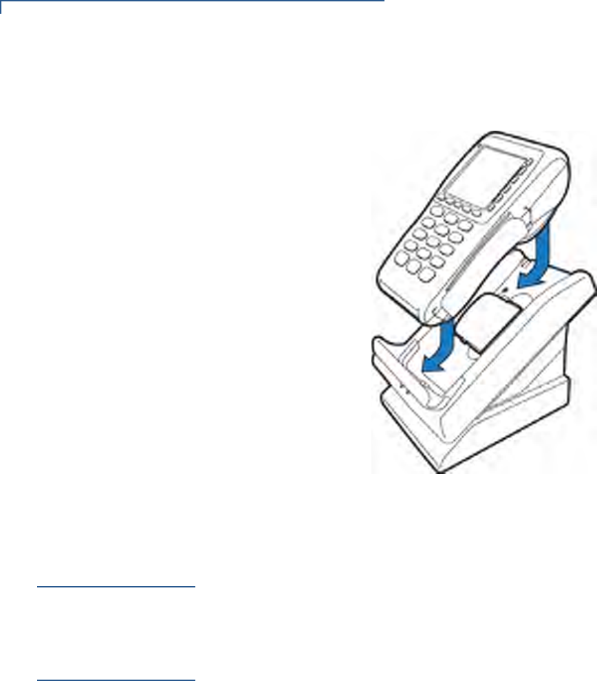
3Place the Vx670 terminal onto the Base Station to charge both the spare and
installed battery packs at the same time.
Figure 31 Charging the Spare and Installed Battery Simultaneously
Conducting
Wireless
Transactions
To conduct a wireless transaction:
•Ensure the terminal is in an optimal position for transmitting.
•Follow the on-screen instructions provided with your application.
Conducting
Smart Card
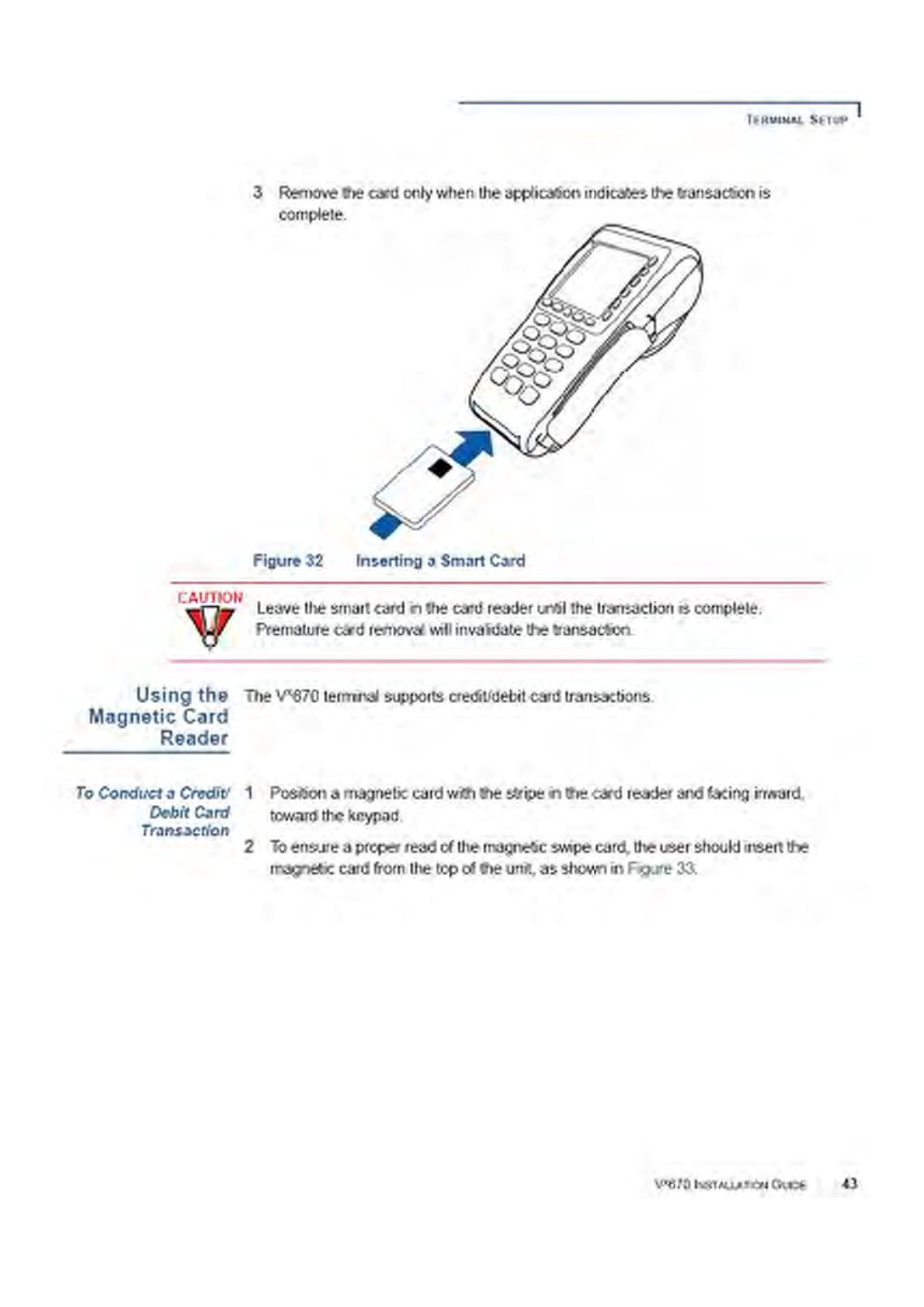
Transactions
The smart card transaction procedure may vary from one application to another.
Verify the procedure with your application provider before performing a smart card
transaction.
To Conduct a Smart
Card Transaction 1Position a smart card with the contacts facing upward (see Figure 32).
2Insert the smart card into the smart card reader slot in a smooth, continuous
motion until it seats firmly.
TERMINAL SETUP
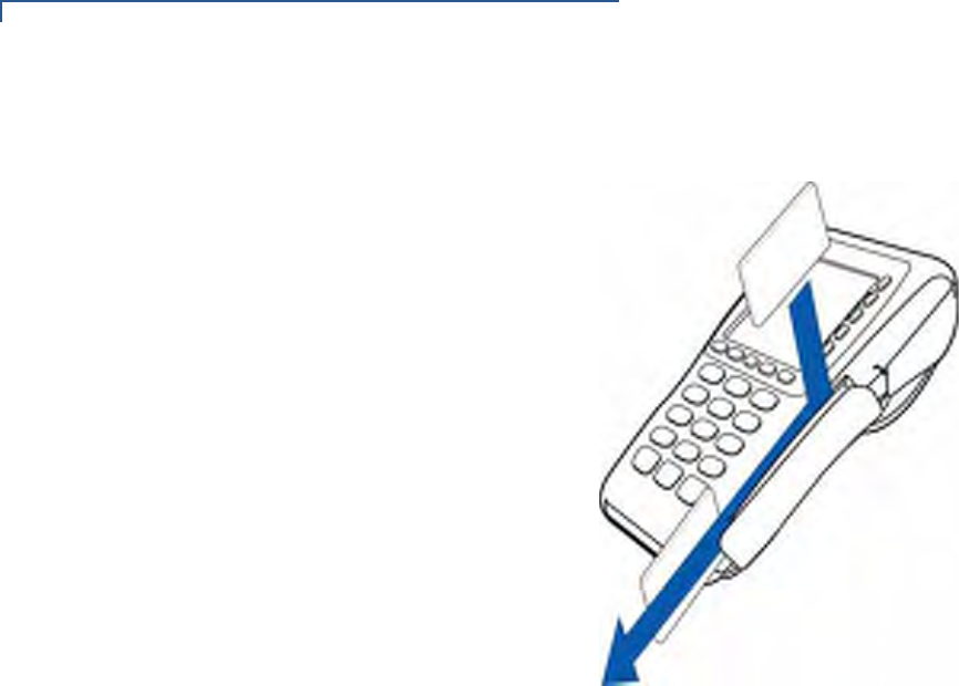
Using the Magnetic Card Reader
44 VX670 INSTALLATION GUIDE
3Swipe the card through the magnetic card reader.
Figure 33 Using the Magnetic Card Reader

VX670 INSTALLATION GUIDE 45
CHAPTER 3
Specifications
This chapter discusses power requirements, dimensions, and other specifications
of the Vx670 terminal.
Power
Vx670 terminal: 12V DC 2.0 A
DC Power Pack
UL, ITE listed, Class 2 power supply:
aInput rated: 100 - 240V AC, 50/60 Hz
bOutput rated: 12V DC 2.0 A
Barrel connector polarity:
Temperature
•Operating temperature: 0° to 40° C (32° to 104° F)
•Storage temperature: -30° to + 60° C (-22° to 140° F)
•Relative humidity: 5% to 90%; non-condensing
External
Dimensions
For Vx670 Terminals:
•Length: 169 mm (6.7 in)
•Width: 81 mm (3.2 in)
•Depth: 60 mm (2.4 in)

SPECIFICATIONS
External Dimensions
46 VX670 INSTALLATION GUIDE
VX670 INSTALLATION GUIDE 47
CHAPTER 4
Maintenance
The Vx670 terminal and base stations have no user-maintainable parts.
Cleaning the
Terminal
To clean the terminal and base station, use a clean cloth slightly dampened with
water and a drop or two of mild soap. For stubborn stains, use alcohol or an
alcohol-based cleaner.
Terminal
Contacts
Gently swab the contacts with alcohol or contact cleaner to remove the dirt. It is
important that the exposed contacts of the Vx670 battery stay clean and unbent.
Smart Card
Reader
Do not attempt to clean the smart card reader. Doing so may void any warranty.
For smart card reader service, contact your VeriFone distributor or service
provider.
CAUTION
Never use thinner, trichloroethylene, or ketone-based solvents – they may cause
deterioration of plastic or rubber parts.
Do not spray cleaners or other solutions directly onto the keypad or terminal
display.
CAUTION
Avoid touching the contacts of the Vx670 battery and the recessed area on the
terminal. Finger oils tarnish contacts, causing bad connections. When operating
on battery power and experiencing a high occurrence of bad or incomplete data
transfers, clean the contacts.

MAINTENANCE
Smart Card Reader
48 VX670 INSTALLATION GUIDE
VERIFONE SERVICE AND SUPPORT
Accessories and Documentation
50 VX670 INSTALLATION GUIDE
cComplete the Inquiry Contact Form at http://www.verifone.com/aboutus/
contact/contact_form.cfm.
•Address the Subject box with to “VeriFone MRA Dept.”
•Reference the model and part number in the Note box.
3Describe the problem(s).
4Provide the shipping address where the repaired or replacement unit must be
returned.
5Keep a record of the following items:
•Assigned MRA number(s).
•VeriFone serial number assigned to the Vx670 terminal, smart battery, or
base station you are returning for service or repair (terminal serial
numbers are located on the bottom of the unit.
•Shipping documentation, such as air bill numbers used to trace the
shipment.
•Model(s) returned (model numbers are located on the VeriFone label on
the bottom of the Vx670 terminal).
Accessories and
Documentation
VeriFone produces the following accessories and documentation for the
Vx670 terminal. When ordering, please refer to the part number in the left column.
•VeriFone online store at www.store.verifone.com
•USA – VeriFone Customer Development Center, 800-VeriFone (837-4366),
Monday - Friday, 7 A.M. - 8 P.M., Eastern time
•International – Contact your VeriFone representative
Power Pack
Contact your local VeriFone distributor to determine which power pack or
power cord fits your needs.
Thermal Printer
Paper
CRM0047-20 Thermal paper in 20-roll bulk package
VeriFone Cleaning
Kit
02746-01 Cleaning Kit
Spare Battery
24016-01-R Vx670 spare battery
NOTE
One MRA number must be issued for each Vx670 terminal you return to VeriFone,
even if you are returning several of the same model.
CPS11224-3B-R DC power pack (universal)
21973-01 AC power cord (US)

VERIFONE SERVICE AND SUPPORT
Accessories and Documentation
VX670 INSTALLATION GUIDE 51
AVX Host Cable
24223-01-R Vx670 AVX Host Cable
Modem Dongle
24123-01-R Vx670 Modem Dongle
Serial Dongle
24122-01-R Vx670 Serial Dongle
Telephone Line
Cord
00124-17 2.1-meter (7-foot) telephone line cord, black, with
modular RJ11-type connectors
Documentation
For Vx670 Terminals:
Vx670 Certifications and Regulations Sheet VPN 24000
Vx670 Quick Installation Guide VPN 24001
Vx670 Reference Manual VPN 24004
Vx670 Base and Dongle Quick Installation Guide VPN 24005
Vx670 Standard Base Quick Installation Guide VPN 24006

VERIFONE SERVICE AND SUPPORT
Accessories and Documentation
52 VX670 INSTALLATION GUIDE
VX670 INSTALLATION GUIDE 53
CHAPTER 6
Troubleshooting
Guidelines
The troubleshooting guidelines provided in the following section are included to
help you install and configure your Vx670 terminal successfully. Typical examples
of malfunction you may encounter while operating your Vx670 terminal and steps
you can take to resolve them are listed in this chapter.
If the problem persists even after performing the outlined guidelines or if the
problem is not described below, contact your local VeriFone representative for
assistance.
Terminal Does
Not Start
•Ensure that the smart battery charge state is not below the critically low level.
•Recharge or replace the smart battery.
•Ensure that you pressed the green ENTER/ON key for approximately 4
seconds, until the unit lights up.
Terminal Display
Does not Show
Correct/
Readable Info
•Recharge or replace the battery.
•Connect the Vx670 terminal into a known-good power supply (if you have one)
to see if this clears the problem.
•If the problem persists, contact your local VeriFone representative for
assistance.
NOTE
The Vx670 terminal comes equipped with tamper-evident labels. The Vx670 unit
contains no user serviceable parts. Do not, under any circumstance, attempt to
disassemble the terminal. Perform only those adjustments or repairs specified in
this guide. For all other services, contact your local VeriFone service provider.
Service conducted by parties other than authorized VeriFone representatives may
void any warranty.
CAUTION
Use only a VeriFone-supplied power pack. Using an incorrectly rated power
supply may damage the terminal or cause it not to work as specified. Before
troubleshooting, ensure that the power supply being used to power the terminal
matches the requirements specified on the bottom of the terminal. (See Chapter
3, Specifications, for detailed power supply specifications.) Obtain the
appropriately rated power supply before continuing with troubleshooting.

TROUBLESHOOTING GUIDELINES
Blank Display
VX670 INSTALLATION GUIDE 55
Blank Display
When the Vx670 terminal display screen does not show correct or clearly readable
information:
•The battery pack may not be connected properly. Remove and reinstall the
battery pack.
•Check terminal power connection.
•Remove and reapply power to the terminal.
•If the problem persists, contact your local VeriFone service provider.
Terminal Does
Not Dial Out
If the terminal does not dial out:
•Check the telephone line connections.
•Check that the telephone line is working by plugging it into a working
telephone and listening for a dial tone.
•Replace the telephone cable that connects the terminal with a cable you know
is working correctly.
•If the problem persists, contact your local VeriFone service provider.
Printer Does Not
Print
If the printer does not work properly:
•Make sure the battery is properly installed in the terminal. The printer will not
print if there is no battery in the terminal.
•Check battery status or terminal power connection. The printer will not print if
there is an insufficient charge remaining in the battery to complete the print
operation.
•Check if the printer is out of paper (slow red blinking light) and that the roll is
properly installed. Open the paper roll cover and install a new roll of printer
paper or ensure that the roll is feeding correctly. A solid red indicator light
indicates a printer error.
•Verify that the printer door is properly latched.
•If the problem persists, contact your VeriFone distributor or service provider.
Printer Paper
Jam
If paper jams inside the printer:
•Press the button at the bottom of the terminal to unlatch the paper roll cover,
then open the cover.
•Remove the damaged paper from the paper roll and clear the feed
mechanism.
•Install a roll of printer paper, as described in Installing the Paper Roll.

TROUBLESHOOTING GUIDELINES
Keypad Does Not Respond
56 VX670 INSTALLATION GUIDE
•If the problem persists, it may be due to poor paper quality. Install a new roll of
higher-quality paper.
Keypad Does
Not Respond
If the keypad does not respond properly:
•Check the terminal display. If it displays the wrong character or nothing at all
when you press a key, follow the steps outlined in Transactions Fail To
Process.
•If pressing a function key does not perform the expected action, refer to the
user documentation for that application to ensure you are entering data
correctly.
•If the problem persists, contact your local VeriFone representative.
Transactions
Fail To Process
There are several reasons why the terminal may not be processing transactions.
Use the following steps to troubleshoot failures.
Check the Magnetic Card Reader
•Perform a test transaction using one or more different magnetic stripe cards to
ensure the problem is not a defective card.
•Ensure that you are swiping cards properly. With the Vx670 card reader, the
black magnetic stripe on the card should face down and inward, toward the
keypad and must be inserted from the top of the terminal (see Figure 33).
•Process a transaction manually, using the keypad instead of the card reader. If
the manual transaction works, the problem may be a defective card reader.
•Contact your VeriFone distributor or service provider.
•If the manual transaction does not work, proceed to Check the Telephone
Line.
Check the Smart Card Reader
•Perform a test transaction using several different smart cards to ensure the
problem is not a defective card.
•Ensure that the card is inserted correctly and that the card is not removed
prematurely.
•Ensure the MSAM cards are properly inserted in the cardholders and that the
cardholders are properly secured (see Installing/Replacing MSAM Cards).
•Contact your VeriFone distributor or service provider.
•If the manual transaction does not process, proceed to Check the Telephone
Line.
WARNING
Poor-quality paper may jam the printer. To order high-quality VeriFone paper,
refer to Accessories and Documentation.