Verifone VX675GPRSCTLS POINT OF SALE TERMINAL User Manual
VeriFone Inc POINT OF SALE TERMINAL Users Manual
Verifone >
Users Manual
VeriFone Part Number DOC265-003-EN-A, Revision A.2
VERIFONE
CONFIDENTIAL
REVISION A.2
VX 675
Installation Guide
3
DEF
2
ABC
1
QZ.
4
GHI
7
PRS
*
5
JKL
8
TUV
0
-SP
X
6
MNO
9
WXY
#
’ ”
’

All rights reserved. No part of the contents of this document may be reproduced or transmitted in any form without the written
permission of VeriFone, Inc.
The information contained in this document is subject to change without notice. Although VeriFone has attempted to ensure the
accuracy of the contents of this document, this document may include errors or omissions. The examples and sample programs are
for illustration only and may not be suited for your purpose. You should verify the applicability of any example or sample program
before placing the software into productive use. This document, including without limitation the examples and software programs, is
supplied “As-Is.”
VeriFone, Inc.
2099 Gateway Place, Suite 600
San Jose, CA, 95110 USA
1-800-VERIFONE
www.verifone.com
VeriFone Part Number DOC265-003-EN-A, Revision A.2
VX 675 Installation Guide
© 2012 VeriFone, Inc.
VERIFONE
CONFIDENTIAL
REVISION A.2
VeriFone, the VeriFone logo, Omni, VeriCentre, and Verix are registered trademarks of VeriFone. Other brand names or trademarks
associated with VeriFone’s products and services are trademarks of VeriFone, Inc.
All other brand names and trademarks appearing in this manual are the property of their respective holders.
Comments? Please e-mail all comments on this document to your local VeriFone Support Team.

VX 675 INSTALLATION GUIDE 3
VERIFONE
CONFIDENTIAL
REVISION A.2
CONTENTS
PREFACE . . . . . . . . . . . . . . . . . . . . . . . . . . . . . . . . . . . . . . . 5
Audience. . . . . . . . . . . . . . . . . . . . . . . . . . . . . . . . . . . . . . . . . . . . . . . . . . . . . . . . 5
Organization . . . . . . . . . . . . . . . . . . . . . . . . . . . . . . . . . . . . . . . . . . . . . . . . . . . . . 5
Related Documentation . . . . . . . . . . . . . . . . . . . . . . . . . . . . . . . . . . . . . . . . . . . . 5
Conventions and Acronyms . . . . . . . . . . . . . . . . . . . . . . . . . . . . . . . . . . . . . . . . . 6
Document Conventions. . . . . . . . . . . . . . . . . . . . . . . . . . . . . . . . . . . . . . . . . . 6
Acronym Definitions . . . . . . . . . . . . . . . . . . . . . . . . . . . . . . . . . . . . . . . . . . . . 7
CHAPTER 1
Terminal Overview Features at a Glance . . . . . . . . . . . . . . . . . . . . . . . . . . . . . . . . . . . . . . . . . . . 9
Features and Benefits . . . . . . . . . . . . . . . . . . . . . . . . . . . . . . . . . . . . . . . . . . . . 10
Exceptional Ease of Use. . . . . . . . . . . . . . . . . . . . . . . . . . . . . . . . . . . . . . . . 10
Performance and Durability . . . . . . . . . . . . . . . . . . . . . . . . . . . . . . . . . . . . . 11
Security . . . . . . . . . . . . . . . . . . . . . . . . . . . . . . . . . . . . . . . . . . . . . . . . . . . . . 11
Communication Technology . . . . . . . . . . . . . . . . . . . . . . . . . . . . . . . . . . . . . 11
CHAPTER 2
Terminal Setup Selecting Terminal Location . . . . . . . . . . . . . . . . . . . . . . . . . . . . . . . . . . . . . . . . 14
Environmental Factors . . . . . . . . . . . . . . . . . . . . . . . . . . . . . . . . . . . . . . . . . 14
Electrical Considerations . . . . . . . . . . . . . . . . . . . . . . . . . . . . . . . . . . . . . . . 14
Unpacking the Shipping Carton . . . . . . . . . . . . . . . . . . . . . . . . . . . . . . . . . . . . . 15
Examining Terminal Features. . . . . . . . . . . . . . . . . . . . . . . . . . . . . . . . . . . . . . . 16
Front Panel . . . . . . . . . . . . . . . . . . . . . . . . . . . . . . . . . . . . . . . . . . . . . . . . . . 16
Examining Connection Ports . . . . . . . . . . . . . . . . . . . . . . . . . . . . . . . . . . . . . . . 17
Power Supply . . . . . . . . . . . . . . . . . . . . . . . . . . . . . . . . . . . . . . . . . . . . . . . . 17
Installing the Paper Roll . . . . . . . . . . . . . . . . . . . . . . . . . . . . . . . . . . . . . . . . . . . 18
Installing the SIM Card . . . . . . . . . . . . . . . . . . . . . . . . . . . . . . . . . . . . . . . . . . . . 20
Using the Smart Battery . . . . . . . . . . . . . . . . . . . . . . . . . . . . . . . . . . . . . . . . . . . 21
Smart Battery Features. . . . . . . . . . . . . . . . . . . . . . . . . . . . . . . . . . . . . . . . . 21
Battery Behavior (No Power Cable) . . . . . . . . . . . . . . . . . . . . . . . . . . . . . . . . . . 22
Manual Startup . . . . . . . . . . . . . . . . . . . . . . . . . . . . . . . . . . . . . . . . . . . . . . . 22
Manual Shutdown . . . . . . . . . . . . . . . . . . . . . . . . . . . . . . . . . . . . . . . . . . . . . 22
Connecting the Terminal Power Pack . . . . . . . . . . . . . . . . . . . . . . . . . . . . . . . . 22
Charging the Smart Battery . . . . . . . . . . . . . . . . . . . . . . . . . . . . . . . . . . . . . . . . 23
Battery Life . . . . . . . . . . . . . . . . . . . . . . . . . . . . . . . . . . . . . . . . . . . . . . . . . . 24
Using the Base Station. . . . . . . . . . . . . . . . . . . . . . . . . . . . . . . . . . . . . . . . . . . . 25
Standard Base Station . . . . . . . . . . . . . . . . . . . . . . . . . . . . . . . . . . . . . . . . . 25
Powering Up the Base Station . . . . . . . . . . . . . . . . . . . . . . . . . . . . . . . . . . . . . . 26
Mounting the Terminal Onto the Base Station . . . . . . . . . . . . . . . . . . . . . . . . . . 27
Conducting Wireless Transactions. . . . . . . . . . . . . . . . . . . . . . . . . . . . . . . . . . . 28
Conducting Smart Card Transactions . . . . . . . . . . . . . . . . . . . . . . . . . . . . . . . . 28
Using the Magnetic Card Reader . . . . . . . . . . . . . . . . . . . . . . . . . . . . . . . . . . . . 29

CONTENTS
4VX 675 INSTALLATION GUIDE
VERIFONE
CONFIDENTIAL
REVISION A.2
CHAPTER 3
Specifications Power . . . . . . . . . . . . . . . . . . . . . . . . . . . . . . . . . . . . . . . . . . . . . . . . . . . . . . . . . 31
DC Power Pack . . . . . . . . . . . . . . . . . . . . . . . . . . . . . . . . . . . . . . . . . . . . . . . . . 31
Operating Environment. . . . . . . . . . . . . . . . . . . . . . . . . . . . . . . . . . . . . . . . . . . . 31
External Dimensions. . . . . . . . . . . . . . . . . . . . . . . . . . . . . . . . . . . . . . . . . . . . . . 31
CHAPTER 4
Maintenance Cleaning the Terminal . . . . . . . . . . . . . . . . . . . . . . . . . . . . . . . . . . . . . . . . . . . . 33
Terminal Contacts . . . . . . . . . . . . . . . . . . . . . . . . . . . . . . . . . . . . . . . . . . . . . . . 33
Smart Card Reader . . . . . . . . . . . . . . . . . . . . . . . . . . . . . . . . . . . . . . . . . . . . . . 33
CHAPTER 5
VeriFone Service
and Support
Returning a Terminal or Smart Battery for Service. . . . . . . . . . . . . . . . . . . . . . . 35
Accessories and Documentation . . . . . . . . . . . . . . . . . . . . . . . . . . . . . . . . . . . . 37
Power Pack. . . . . . . . . . . . . . . . . . . . . . . . . . . . . . . . . . . . . . . . . . . . . . . . . . 37
Printer Paper. . . . . . . . . . . . . . . . . . . . . . . . . . . . . . . . . . . . . . . . . . . . . . . . . 37
VeriFone Cleaning Kit . . . . . . . . . . . . . . . . . . . . . . . . . . . . . . . . . . . . . . . . . . 37
Documentation . . . . . . . . . . . . . . . . . . . . . . . . . . . . . . . . . . . . . . . . . . . . . . . 38
CHAPTER 6
Troubleshooting
Guidelines
Terminal Does Not Start . . . . . . . . . . . . . . . . . . . . . . . . . . . . . . . . . . . . . . . . . . . 39
Terminal Display Does Not Show Correct/Readable Info. . . . . . . . . . . . . . . . . . 39
Smart Battery Does Not Charge. . . . . . . . . . . . . . . . . . . . . . . . . . . . . . . . . . . . . 40
Spare Battery in Base Station Does Not Charge . . . . . . . . . . . . . . . . . . . . . . . . 40
Blank Display . . . . . . . . . . . . . . . . . . . . . . . . . . . . . . . . . . . . . . . . . . . . . . . . . . . 40
Terminal Does Not Dial Out . . . . . . . . . . . . . . . . . . . . . . . . . . . . . . . . . . . . . . . . 41
Printer Does Not Print. . . . . . . . . . . . . . . . . . . . . . . . . . . . . . . . . . . . . . . . . . . . . 41
Printer Paper Jam. . . . . . . . . . . . . . . . . . . . . . . . . . . . . . . . . . . . . . . . . . . . . . . . 41
Keypad Does Not Respond . . . . . . . . . . . . . . . . . . . . . . . . . . . . . . . . . . . . . . . . 42
Transactions Fail to Process . . . . . . . . . . . . . . . . . . . . . . . . . . . . . . . . . . . . . . . 42
INDEX . . . . . . . . . . . . . . . . . . . . . . . . . . . . . . . . . . . . . . . . .45

VX 675 INSTALLATION GUIDE 5
VERIFONE
CONFIDENTIAL
REVISION A
PREFACE
This guide is your primary source of information for setting up and installing the
VX 675 terminal.
Audience
This guide is useful for anyone installing and configuring a VX 675 terminal. Basic
descriptions of the terminal features are also provided.
Organization
This guide is organized as follows:
Chapter 1, Terminal Overview. Provides an overview of the VX 675 terminal.
Chapter 2, Termi nal Set up. Explains how to set up and install the VX 675 terminal.
Provides information on how to select a location, establish power and telephone
line connections, and how to configure optional peripheral devices.
Chapter 3, Specifications. Discusses power requirements and dimensions of the
VX 675 terminal.
Chapter 4, Maintenance. Explains how to maintain your VX 675 terminal.
Chapter 5, VeriFone Service and Support. Provides information on contacting
your local VeriFone representative or service provider, and information on how to
order accessories or documentation from VeriFone.
Chapter 6, Troubleshooting Guidelines. Provides troubleshooting guidelines,
should you encounter a problem in terminal installation and configuration.
Related
Documentation
To learn more about the VX 675 terminal, refer to the following set of documents:
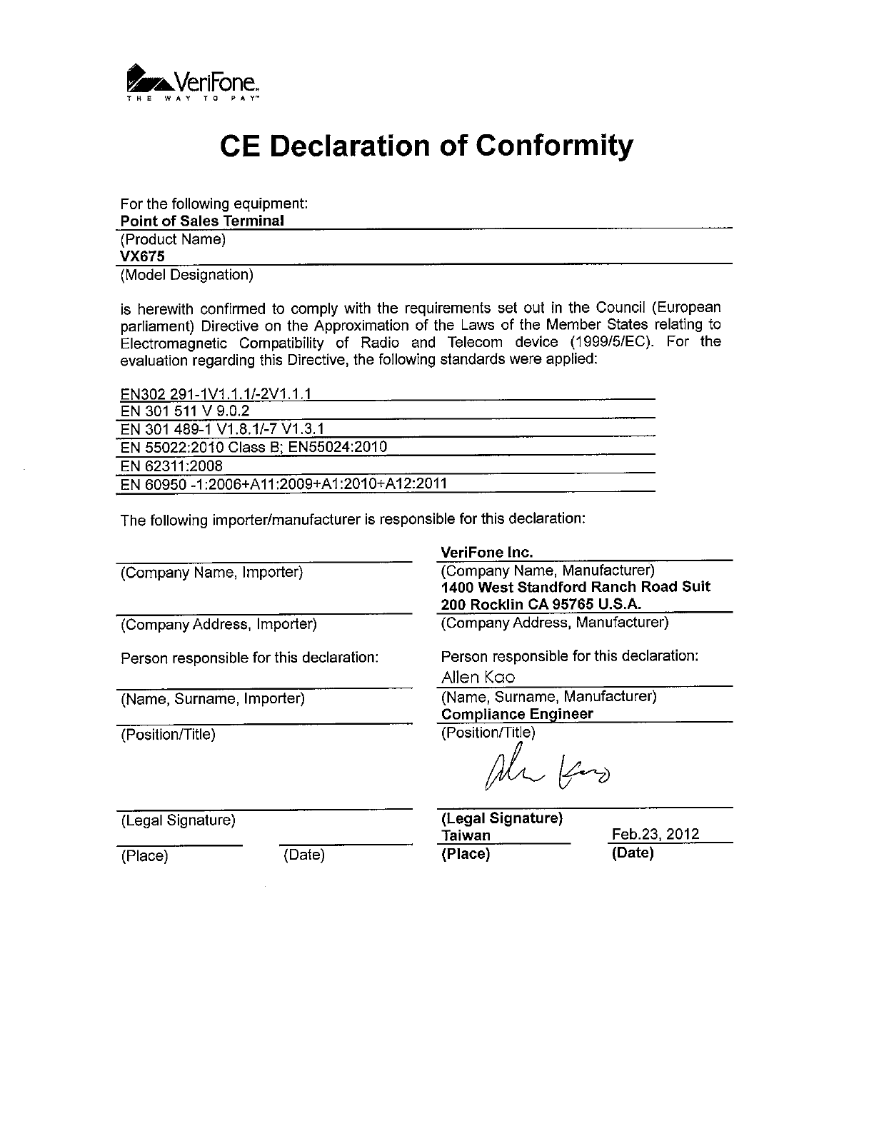
VX 675 Certifications and Regulations Sheet VPN DOC265-001-EN-A
VX 675 Quick Installation Guide VPN DOC265-002-EN-A
VX 675 Reference Guide VPN DOC265-004-EN-A
Verix eVo Volume I: Operating System
Programming Manual
VPN DOC00301
Verix eVo Volume II: Operating System and
Communications Programmers Manual
VPN DOC00302
Verix eVo Volume III: Operating System
Programming Tools Reference Manual
VPN DOC00303
PREFACE
Conventions and Acronyms
6VX 675 INSTALLATION GUIDE
VERIFONE
CONFIDENTIAL
REVISION A
Conventions and
Acronyms
This section describes the conventions and acronyms used in this guide.
Document
Conventions
Various conventions are used to help you quickly identify special formatting. Table
1 describes these conventions and provides examples of their use.
Table 1 Document Conventions
Convention Meaning Example
Blue Text in blue indicates terms
that are cross referenced.
See Conventions and Acronyms.
Italics Italic typeface indicates
book titles or emphasis.
You must install a roll of thermal-
sensitive paper in the printer.
Courier The courier type face is
used while specifying
onscreen text, such as text
that you would enter at a
command prompt, or to
provide an URL.
http://www.verifone.com
The pencil icon is used to
highlight important
information.
RS-232-type devices do not work
with the PINpad port.
The caution symbol
indicates possible hardware
or software failure, or loss
of data.
The terminal is not waterproof or
dustproof, and is intended for indoor
use only.
The lightning symbol is
used as a warning when
bodily injury might occur.
Due to risk of shock do not use the
terminal near water.
NOTE
CAUTION
WARNING

PREFACE
Conventions and Acronyms
VX 675 INSTALLATION GUIDE 7
VERIFONE
CONFIDENTIAL
REVISION A
Acronym Definitions
Various acronyms are used in place of the full definition. Table 2 presents
acronyms and their definitions.
Table 2 Acronym Definitions
Acronym Definitions
AC Alternating Current
CDMA Code Division Multiple Access
EMV Joint Europay, MasterCard and Visa Standard
GPRS General Packet Radio Service
GSM Global System for Mobile Communication
HDMI High-Definition Multimedia Interface
ITP Internal Thermal Printer
LCD Liquid Crystal Display
LED Light Emitting Diode
MRA Merchandise Return Authorization
MSAM Micromodule-Size Security Access Module
PED PIN Entry Device
PIN Personal Identification Number
POS Point-of-Sale
QVGA Quarter Video Graphics Array
RJ45 Registered Jack 45
RS-232 Recommended Standard 232
R-UIM Removable User Identity Module
SAM Security Access Module
SD Secure Digital
SIM Subscriber Identity Module
TFT Thin Film Transistor
UART Universal Asynchronous Transmitter/Receiver
USB Universal Serial Bus
VPN VeriFone Part Number

PREFACE
Conventions and Acronyms
8VX 675 INSTALLATION GUIDE
VERIFONE
CONFIDENTIAL
REVISION A
VX 675 INSTALLATION GUIDE 9
VERIFONE
CONFIDENTIAL
REVISION A
CHAPTER 1
Terminal Overview
This chapter provides a brief description of the VX 675 terminal. This terminal
features a large color screen display, fast processor, abundant memory, and PCI
2.0 and PCI 3.0 security.
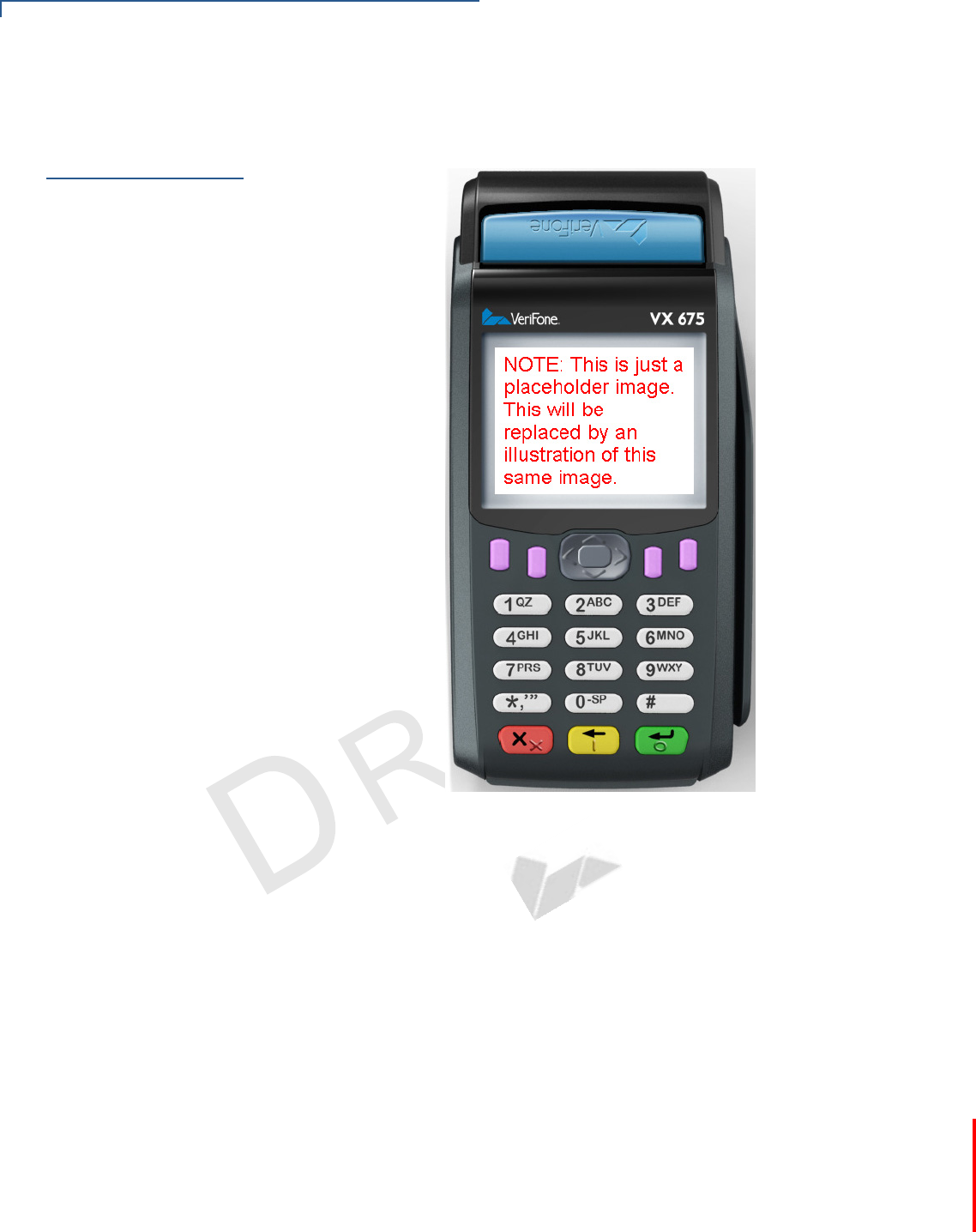
The VX 675 terminal is a portable, battery-powered device designed to fit
comfortably during handheld consumer-facing applications. It features a vibrantly
colored 2.8” TFT QVGA display and a backlit spill-resistant keypad. It supports the
GPRS communications technology.
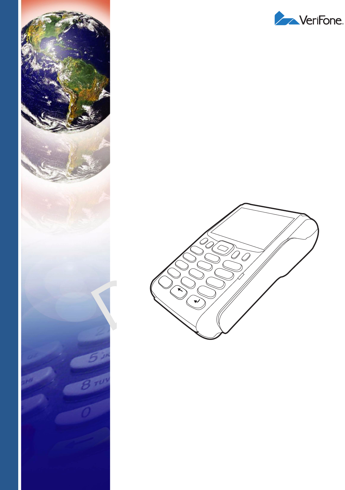
Figure 1 The VX 675 Terminal
Features at a Glance
The following are the features of VX 675:
NOTE VeriFone ships variants of the VX 675 terminal for different markets. Your terminal
may have a different configuration. The following devices may or may not be
present: a smart card reader, none or three MSAM cardholders, and a SIM/R-UIM
cardholder.
3
DEF
2
ABC
1
QZ.
4
GHI
7
PRS
*
5
JKL
8
TUV
0
-SP
X
6
MNO
9
WXY
#
’ ”
’
•400 MHz ARM11 RISC processor
delivers power and usability in a
convenient “hand-over” design.
•Securely supports and runs payment
and value-added applications along
with signature capture.
•Multi-application operating
environment.
•Offers unsurpassed performance on
EMV smart card transactions

TERMINAL OVERVIEW
Features and Benefits
10 VX 675 INSTALLATION GUIDE
VERIFONE
CONFIDENTIAL
REVISION A
Features and
Benefits
VX 675 terminals provide the right combination of features and functions including
a triple-track magnetic stripe card reader, smart card reader, integrated PIN pad,
color screen display, and a quiet yet fast internal thermal printer (ITP).
Exceptional Ease of
Use
•Lightweight, tapered design, compact, stylish and the ergonomic balance
allows convenient terminal hand-off to the consumer for PIN entry or other
input.
•Large 2.8” color TFT display for boundless application possibilities and easy
readability under various lighting conditions.
•Large, blue backlit keys provide tactile response to simplify usage and
minimize finger slips.
•25 mm and 40 mm diameter paper roll support with a trouble-free, drop-in,
“clam shell” loading and dual tear bar that allow receipts to be torn in any
direction.
•Quiet and fast integrated thermal printer with a rear placement to maximize
the user interface area.
•Vertical magnetic stripe card reader with an extended blade for optimal card
reading.
•Optional hands-free holster is available that fits the server’s or clerk’s belt so
that the POS device can be quickly removed and easily handed to the
customer.
•Advanced memory architecture to
meet tomorrow’s needs with support
for 192 MB.
•Max UI design provides large 2.8” color
QVGA display, and large blue backlit
keys for easier viewing.
•Backward compatibility with VeriFone
solutions help reduces development
costs.
•Adds vibrant color screen to the
smallest purpose-built wireless payment
device.
•Drop-resistant design minimizes
breakage.
•Multiple connectivity options.
•32-bit processing and multi-tasking
capabilities.
•Spill-resistant design forces liquid down
and off the front of the terminal.
•Security architecture exceeds
specifications for PCI-PED and
sophisticated file authentication.

TERMINAL OVERVIEW
Features and Benefits
VX 675 INSTALLATION GUIDE 11
VERIFONE
CONFIDENTIAL
REVISION A
Performance and
Durability
•Fast transactions due to powerful 400 MHz ARM11 processor.
•High-capacity 3.7 V 2250 mAH Li-ion battery.
•Standard base station for drop-and-go charging.
•Rounded corners and drop resistant to 3 feet on concrete floor to minimize
breakage.
•192 MB of memory with optional removable SD flash memory.
Security
•PCI PED 2.0 and PCI PED 3.0 approved for debit and other PIN-based
transactions.
•EMV Level 1 and 2 Type Approval.
•Tamper-resistant construction, SSL protocols, and VeriShield file
authentication.
Communication
Technology
•VX 675 GPRS and 3G: Long-range wireless payment for retailers that have no
physical location limitations.

TERMINAL OVERVIEW
Features and Benefits
12 VX 675 INSTALLATION GUIDE
VERIFONE
CONFIDENTIAL
REVISION A

VX 675 INSTALLATION GUIDE 13
VERIFONE
CONFIDENTIAL
REVISION A
CHAPTER 2
Terminal Setup
This chapter describes the terminal setup procedures. You will learn about:
•Selecting Terminal Location.
•Unpacking the Shipping Carton.
•Examining Terminal Features.
•Examining Connection Ports.
•Installing the Paper Roll.
•Installing the SIM Card.
•Using the Smart Battery.
•Battery Behavior (No Power Cable).
•Charging the Smart Battery.
•Connecting the Terminal Power Pack.
•Using the Base Station.
•Mounting the Terminal Onto the Base Station.
•Conducting Wireless Transactions.
•Conducting Smart Card Transactions.
•Using the Magnetic Card Reader.
•Using the Magnetic Card Reader.

TERMINAL SETUP
Selecting Terminal Location
14 VX 675 INSTALLATION GUIDE
VERIFONE
CONFIDENTIAL
REVISION A
Selecting
Terminal
Location
Use the following guidelines when selecting a location for your VX 675 terminal.
Environmental
Factors
•The VX 675 unit is a portable terminal. Select a flat support surface, such as a
countertop or table, to keep the terminal safe in between uses.
•Do not use the terminal where there is high heat, dust, humidity, moisture, or
caustic chemicals or oils.
•Keep the terminal away from direct sunlight and anything that radiates heat,
such as a stove or motor.
•Do not use the terminal outdoors.
Electrical
Considerations
•Avoid using this product during electrical storms.
•Avoid locations near electrical appliances or other devices that cause
excessive voltage fluctuations or emit electrical noise (for example, air
conditioners, electric motors, neon signs, high-frequency or magnetic security
devices, or computer equipment).
•Do not use the terminal near water or in moist conditions.
CAUTION The terminal is not waterproof or dustproof, and is intended for indoor use only.
Any damage to the unit from exposure to rain or dust may void any warranty.
TERMINAL SETUP
Unpacking the Shipping Carton
VX 675 INSTALLATION GUIDE 15
VERIFONE
CONFIDENTIAL
REVISION A
Unpacking the
Shipping Carton
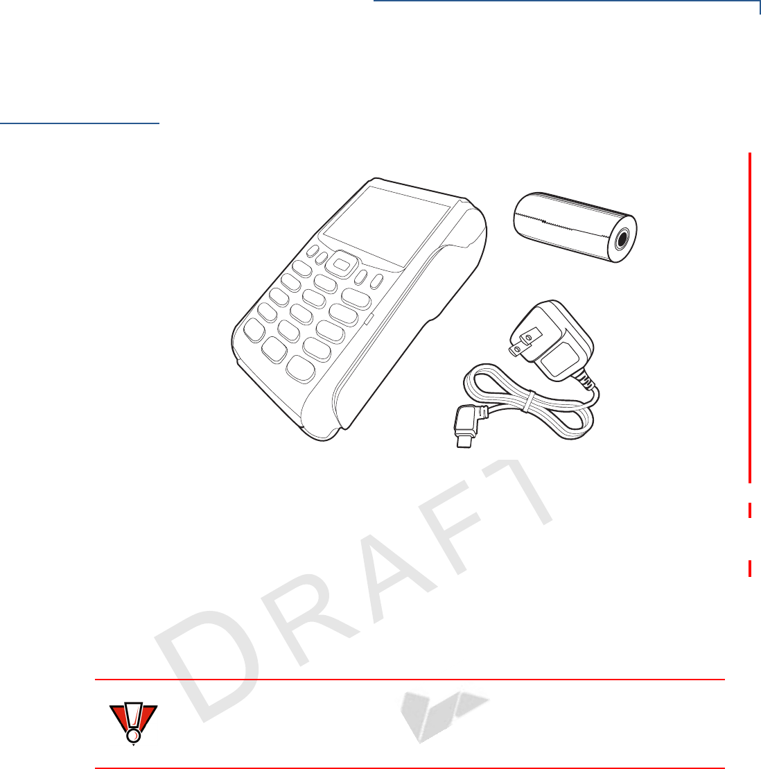
Open the shipping carton and carefully inspect its contents for possible tampering
or shipping damage. The VX 675 device is a secure product and any tampering
may cause the terminal to cease to function properly.
Figure 2 VX 675 Shipping Carton Contents
To unpack the
Shipping Carton
1Remove and inspect the following items:
•Terminal
•Power pack
•Paper roll
2Remove all plastic wrapping from the terminal and other components.
3Remove the clear protective film from the LCD screen.
4Save the shipping carton and packing material for future repacking or moving
the terminal.
CAUTION Do not use a terminal that has been damaged or tampered with. The
VX 675 terminal comes equipped with tamper-evident labels. If a label or
component appears damaged, please notify the shipping company and your
VeriFone representative or service provider immediately.
TERMINAL SETUP
Examining Terminal Features
16 VX 675 INSTALLATION GUIDE
VERIFONE
CONFIDENTIAL
REVISION A
Examining
Terminal
Features
Before you continue the installation process, notice the features of the
VX 675 terminal (see illustration below).
Figure 3 VX 675 Terminal Features (Front Panel)
Front Panel
The front panel includes the following features:
•A Large 3.5” color TFT screen display.
•Two types of keys:
aA 12-key, telephone-style keypad (keypads may vary in style).
bThree color-coded function keys below the keypad (from left to right:
CANCEL, CLEAR, ENTER).
•A magnetic card reader, built into the right side. Swipe the card using the
proper direction, with the magnetic stripe down and facing inward, toward the
keypad.
•An internal thermal printer at the top front of the terminal.
•A smart card reader, built into the bottom of the terminal. For directions on
how to use a smart card, see Conducting Smart Card Transactions.
TERMINAL SETUP
Examining Connection Ports
VX 675 INSTALLATION GUIDE 17
VERIFONE
CONFIDENTIAL
REVISION A
•A SAM (security access module) compartment, built into the bottom of the
terminal inside the back compartment. The VX 675 terminal contains an
MSAM cardholder to support stored-value card programs or other merchant
card requirements.
Examining
Connection
Ports
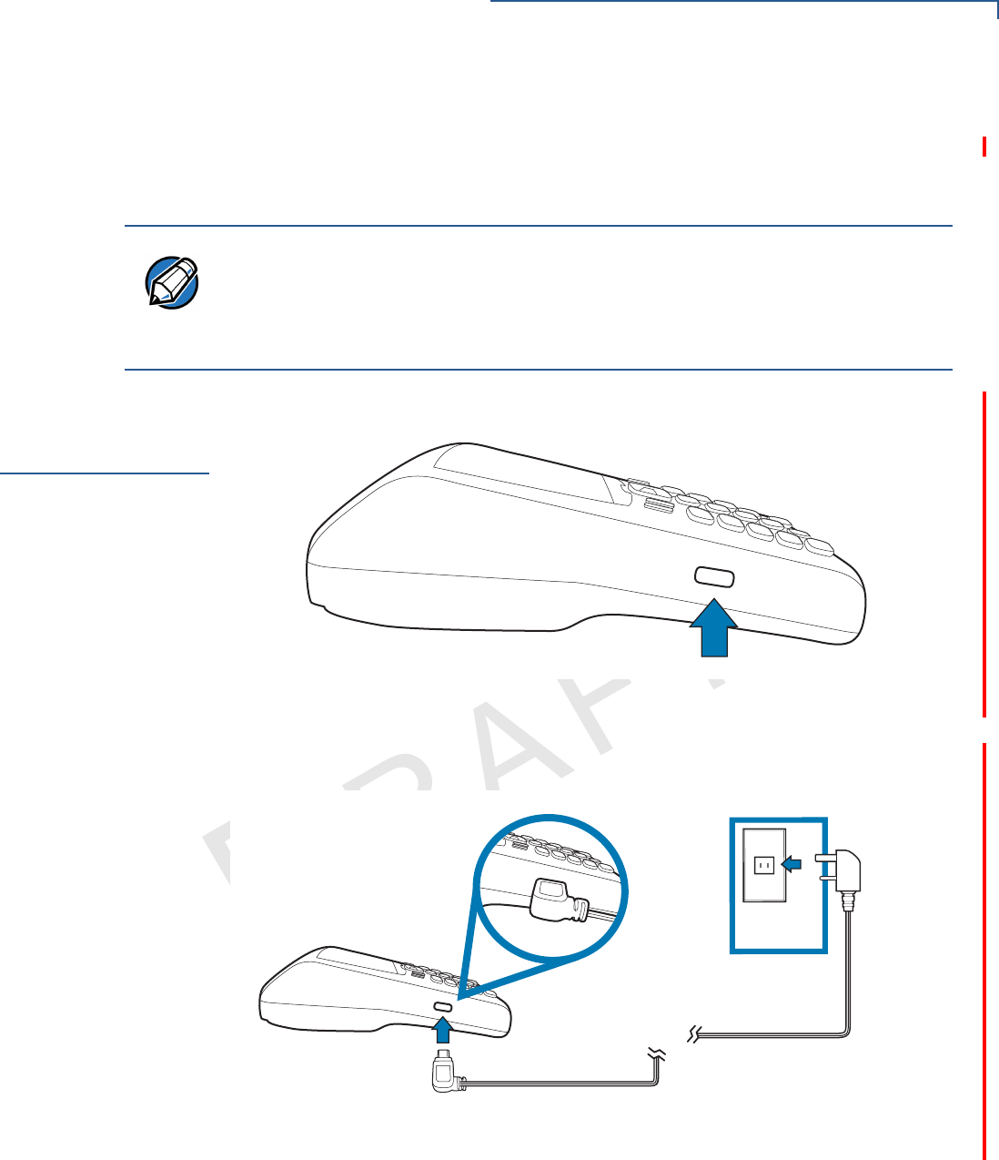
The VX 675 terminal has one primary micro-USB port.
Figure 4 The VX 675 Primary Micro-USB Port
Power Supply
Each VX 675 terminal comes with power supply (VPN CBL268-004-01-A) used to
connect the terminal directly to a power outlet and to charge the battery.
Figure 5 Power Supply Connection to a VX 675 Terminal
NOTE VeriFone ships variants of the VX 675 terminal for different markets. Your terminal
may have a different configuration. The following devices may or may not be
present: a smart card reader, or an MSAM cardholder. However, the basic
processes described in this guide remain the same, regardless of terminal
configuration.
TERMINAL SETUP
Installing the Paper Roll
18 VX 675 INSTALLATION GUIDE
VERIFONE
CONFIDENTIAL
REVISION A
Installing the
Paper Roll
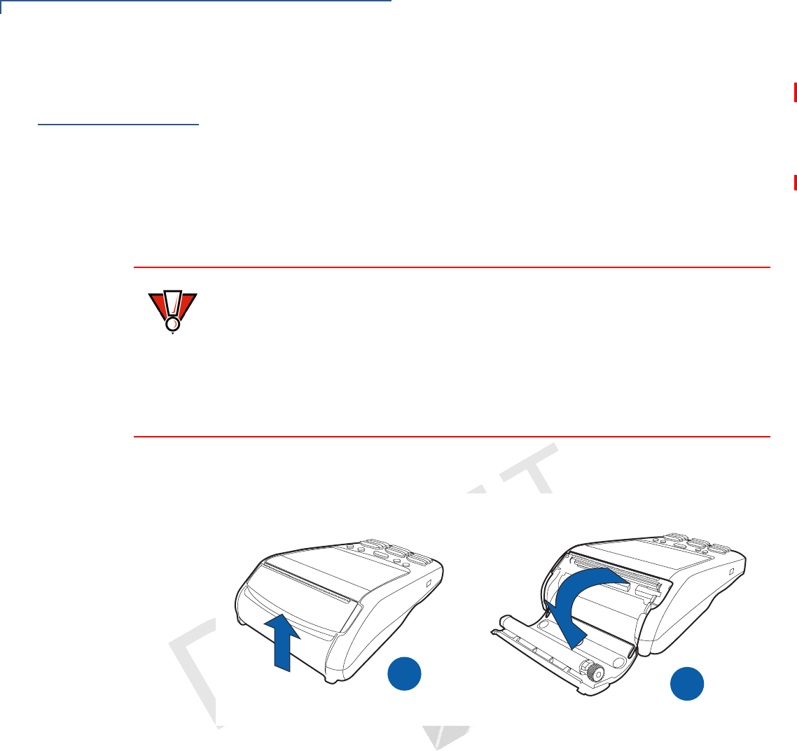
A fast, quiet thermal printer is built into the VX 675 terminal. Before you can
process transactions that require a receipt or record, you must install a roll of
thermal-sensitive paper in the printer.
The ITP uses a roll of single-ply, thermal-sensitive paper 57 millimeters (2.24
inches) wide and 25 or 40 millimeters in diameter. A pink out-of-paper indicator
line appears on the edge of the paper approximately 18 inches before the end of
the roll. After this line appears, there is enough paper remaining on the roll to
conclude at least one transaction.
To Install a Paper Roll 1Gently pull the latch located on the bottom of the terminal to unlock the paper
roll cover.
Figure 6 Unlocking the Printer Cover
2Lift the printer cover up and back.
3Remove any partial roll of paper in the printer tray.
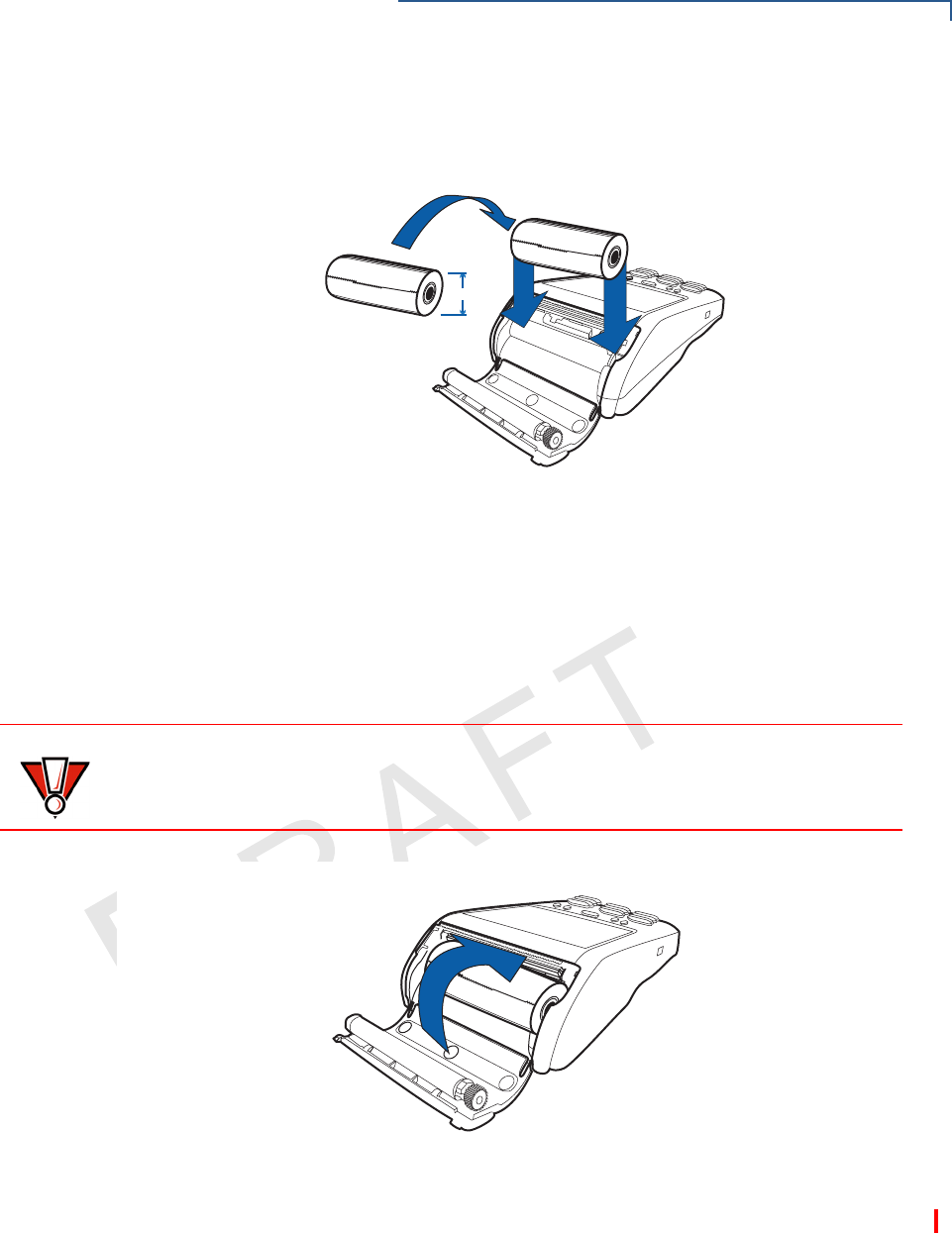
4Loosen the glued leading edge of the new roll of paper or remove the
protective strip, if applicable. Unwind the paper roll past any glue residue.
5Hold the roll so the paper feeds from the bottom of the roll when the terminal is
inverted (see illustration below).
CAUTION Poor-quality paper can jam the printer and create excessive paper dust. To order
high-quality VeriFone paper, refer to Accessories and Documentation.
Store thermal paper in a dry, dark area. Handle thermal paper carefully: impact,
friction, temperature, humidity, and oils affect the color and storage
characteristics of the paper.
Never load a roll of paper with folds, wrinkles, tears, or holes at the edges in the
print area.
B
A
TERMINAL SETUP
Installing the Paper Roll
VX 675 INSTALLATION GUIDE 19
VERIFONE
CONFIDENTIAL
REVISION A
6Drop the paper roll into the printer tray.
Figure 7 Loading Paper Roll
7Pull paper up past the glue residue on the paper roll.
8Close the paper roll cover by gently pressing directly on the cover until it clicks
shut, allowing a small amount of paper past the glue residue to extend outside
the printer door.
Figure 8 Closing Paper Roll Cover
9Tear the paper off against the serrated plastic strip in the printer.
25mm
CAUTION To prevent damaging the print roller, always gently press down on the paper roll
cover to close it.
TERMINAL SETUP
Installing the SIM Card
20 VX 675 INSTALLATION GUIDE
VERIFONE
CONFIDENTIAL
REVISION A
Installing the
SIM Card
The VX 675 terminal for GPRS modems supports the installation of a GSM SIM
(Subscriber Identity Module). Use the following procedure to install a SIM card.
To install or replace
the card
1Turn off the terminal.
2Place the terminal upside down on a soft, clean surface to protect the lens
from scratches.
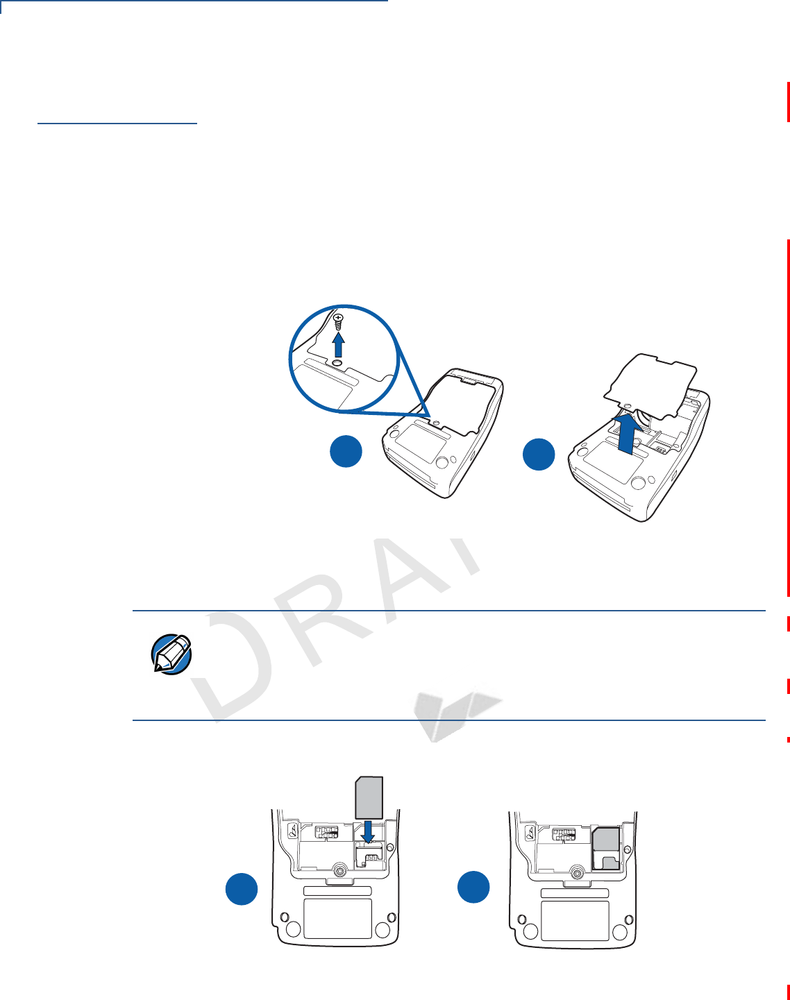
3Unscrew and remove the back compartment cover.
4Lift the battery pack.
Figure 9 Removing the Back Compartment Cover
5Insert the SIM card into the cardholder.
Figure 10 Inserting the SIM Card
AB
NOTE There is only one SIM slot. Before inserting the SIM card, position it as shown in
in the illustration below, with the card’s gold contacts facing the compartment. The
cardholder connector base has a set of contacts and a notch to ensure the SIM/R-
UIM card is positioned correctly. The SIM card has a notch on one corner to
ensure that it fits into the connector base in only one way.
B
A
MIS
M
IS

TERMINAL SETUP
Using the Smart Battery
VX 675 INSTALLATION GUIDE 21
VERIFONE
CONFIDENTIAL
REVISION A
6Return the battery pack to its original position.
7Close and screw the back compartment cover.
Using the Smart
Battery
The VX 675 terminal uses a Li-ion smart battery (see Accessories and
Documentation for ordering information). The internal logic of the smart battery
prevents both overcharging and undercharging (a fault condition in which the
battery level goes well below the minimum acceptable charge and the battery
becomes unusable).
Smart Battery
Features
The following are features of the smart battery:
•Two Li-ion cells
•A fuel gauge module that:
•Monitors state of charge (voltage and percentage of capacity).
•Communicates with the terminal (charge parameters and status).
•Determines full charge capacity (on charge cycle and uninterrupted
discharge cycle).
•Automatically shuts down when the charge is critically low.
•A safety circuit that:
•Prevents cell damage from overcharge, over-discharge, or overheating.
•Activates when the battery is left in an unused terminal for extended
periods.
NOTE The VX 675 terminal will operate on battery power or on power pack power. The
smart battery charger in the terminal will be active whenever the power pack is
connected.
NOTE •VX 675 battery pack is not customer changeable and therefore should not be
disconnected and removed.
•Li-ion batteries are not affected by shallow charging. Furthermore, when the
terminal has no external power source or smart battery, the coin cell battery
provides power to the security circuit.
•Disconnecting and removing the battery, as well as unplugging the terminal
power pack, reduce the life of the coin cell battery, which does not recharge
and must be replaced if drained.
•Conserve battery power by turning the VX 675 terminal off when not in use.
Keep the Li-ion battery inserted in the terminal and power up the terminal
periodically to check the battery charge. Do not let the battery charge fall
below 10% for extended periods of time as this may permanently diminish the
battery capacity. Recharge the battery by attaching the power cable to the
terminal and plugging the power pack into a wall outlet.

TERMINAL SETUP
Battery Behavior (No Power Cable)
22 VX 675 INSTALLATION GUIDE
VERIFONE
CONFIDENTIAL
REVISION A
Battery Behavior
(No Power
Cable)
The terminal shifts to cabled power mode and starts up automatically when the
VX 675 is connected to a non-battery power source, regardless of the battery
charge state.
Manual Startup
Hold the green key down for about 4 seconds until the terminal displays the
startup screen.
The terminal lights up and the green LED indicator activates once the power is on.
Manual Shutdown
Hold the red key down for about 4 seconds until the terminal displays the
shutdown verification screen. Keep holding the red key until the VX 675 terminal
shuts down.
Connecting the
Terminal Power
Pack
After installing the smart battery, connect the VX 675 terminal to the provided
power source for initial charging.
NOTE The 4-second power-up delay prevents terminal startup if the green key is
accidentally held down. The time required to hold the green key down to power up
the terminal is configurable (for more information, see the VX 675 Reference
Guide – VPN DOC265-004-EN-A).
NOTE The VeriFone copyright screen starts and displays a unique copyright screen
once the terminal loads an application. However, DOWNLOAD NEEDED appears on
screen after the initial VeriFone copyright screen if there is no available
application in the terminal.
NOTE •The 4-second shutdown delay that prevents terminal shutdown if the red key
is accidentally held down. The time required to hold the red key down to shut
down the terminal is configurable (for more information, see the VX 675
Reference Guide – VPN DOC265-004-EN-A).
•The screen is blank and the green LED indicator is off when the terminal has
no power.
CAUTION Using an incorrectly rated power supply may damage the terminal or cause it not
to work as specified. Before troubleshooting, ensure that the power supply being
used to power the terminal matches the requirements specified on the bottom of
the terminal. (See Specifications for detailed power supply specifications.) Obtain
the appropriately rated power supply before continuing with troubleshooting.
WARNING Do not plug the power pack into an outdoor outlet or operate the terminal
outdoors.
During a transaction, disconnecting the power by removing the battery or
unplugging the terminal from a wall power while at very low battery charge may
cause transaction data files not yet stored in the terminal memory to be lost.
TERMINAL SETUP
Charging the Smart Battery
VX 675 INSTALLATION GUIDE 23
VERIFONE
CONFIDENTIAL
REVISION A
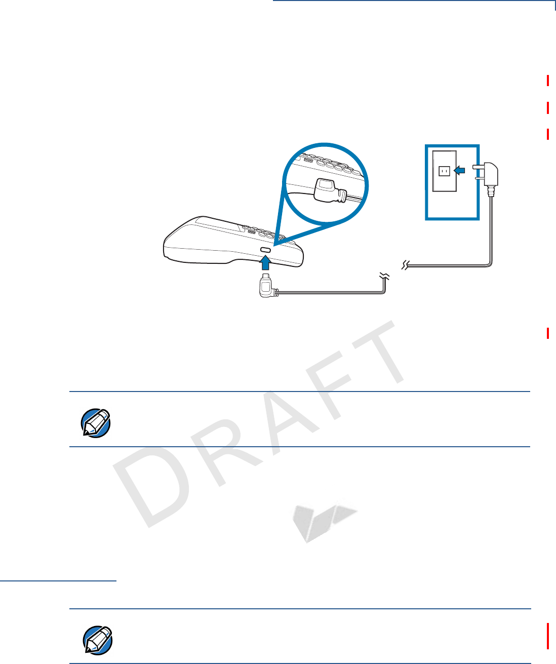
The VX 675 unit comes with a universal input power pack capable of operating
from voltages of 100 V to 240 V AC.
To Connect the
Terminal Power
Supply
1Insert the micro-USB plug into the micro-USB port of the VX 675, as shown in
the figure below.
Figure 11 VX 675 Power Supply Connection
2Insert the AC power cable into the power pack.
3Plug the AC power cable into a wall outlet or powered surge protector.
The light indicators on the VX 675 appear when the terminal receives power.
Once it loads the application, the terminal starts the initial VeriFone copyright
screen and displays a unique copyright screen. If there is no available application
in the terminal, DOWNLOAD NEEDED appears on screen after the initial VeriFone
copyright screen.
Charging the
Smart Battery
After unpacking your VX 675 terminal, install the battery and connect the power
pack to the unit for 6 hours or until fully charged.
The smart battery has a safety circuit to protect the Li-ion cells from overcharging
and over-discharging. If the battery is over-discharged, the safety circuit shuts
down the battery. The battery must then be recharged to restore operation.
NOTE To protect against possible damage caused by lightning strikes and electrical
surges, consider installing a power surge protector.
NOTE The terminal charges the VX 675 smart battery when the terminal is in the base
station. For more information, see Mounting the Terminal Onto the Base Station.
TERMINAL SETUP
Charging the Smart Battery
24 VX 675 INSTALLATION GUIDE
VERIFONE
CONFIDENTIAL
REVISION A
Battery Life
Charging and discharging the VX 675 smart battery hundreds of times will wear
out the battery. Significantly reduced operating times indicate the need for battery
replacement (see Accessories and Documentation for ordering information).
NOTE The VX 675 terminal automatically shuts off when the smart battery reaches the
critically low charge state. If this occurs, the smart battery must be recharged for a
minimum of 1/2 hour before it can power the terminal. It may take several
recharge attempts to reset the safety circuit when charging a smart battery that
has been discharged below this critical state.
WARNING Do not dispose of batteries in a fire. Li-ion batteries must be recycled
or disposed of properly. Do not dispose of Li-ion batteries in municipal
waste sites.

TERMINAL SETUP
Using the Base Station
VX 675 INSTALLATION GUIDE 25
VERIFONE
CONFIDENTIAL
REVISION A
Using the Base
Station
The primary purpose of the base station is to charge the terminal battery and
provide a docking station for the terminal after being used. The Base Station can
be positioned on a countertop or mounted to the wall.
Standard Base
Station
The standard Base Station can charge the VX 675 terminal. However, it does not
have any external ports and has a single LED to indicate power status.
Figure 12 The VX 675 Standard Base Station
TERMINAL SETUP
Powering Up the Base Station
26 VX 675 INSTALLATION GUIDE
VERIFONE
CONFIDENTIAL
REVISION A
Powering Up the
Base Station
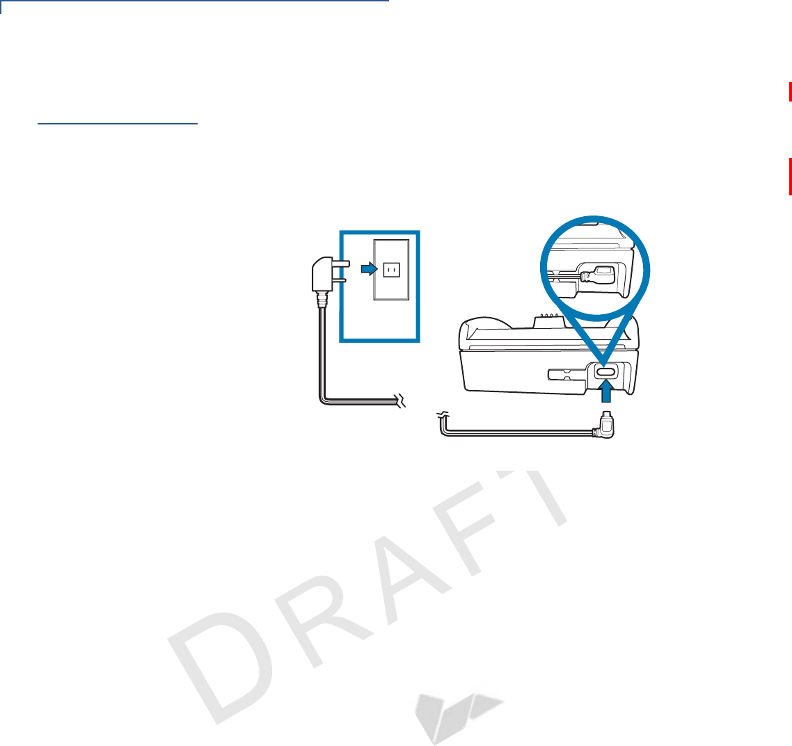
Use the procedure in this section to connect the VX 675 Base Stations to a power
source.
To power up the base
station
1Insert the micro-USB plug into the micro-USB port of the base station, as
shown in the figure below.
Figure 13 Connecting the Base Station to a Power Source
2Insert the AC power cable into the power pack.
3Plug the AC power cable into a wall outlet or power surge protector.
4Confirm that the Base Station is powered up as indicated by the solid green
LED.
TERMINAL SETUP
Mounting the Terminal Onto the Base Station
VX 675 INSTALLATION GUIDE 27
VERIFONE
CONFIDENTIAL
REVISION A
Mounting the
Terminal Onto
the Base Station
The VX 675 terminal can be placed on the Base Station when not in use for
continuous charging of its battery.
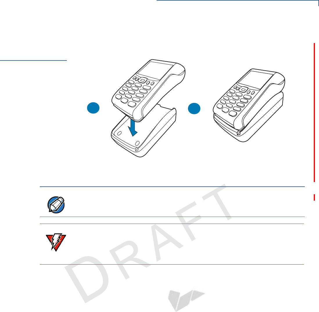
Figure 14 Placing the VX 675 terminal onto the Base Station
AB
NOTE To protect against possible damage caused by lightning strikes and electrical
surges, consider installing a power surge protector.
WARNING Do not plug the power pack into an outdoor outlet or operate the terminal
outdoors.
Disconnecting the power during a transaction may cause transaction data files
not yet stored in terminal memory to be lost.
TERMINAL SETUP
Conducting Wireless Transactions
28 VX 675 INSTALLATION GUIDE
VERIFONE
CONFIDENTIAL
REVISION A
Conducting
Wireless
Transactions
To conduct a wireless transaction:
•Ensure the terminal is in an optimal position for transmitting.
•Follow the on-screen instructions provided with your application.
Conducting
Smart Card
Transactions
The smart card transaction procedure may vary from one application to another.
Verify the procedure with your application provider before performing a smart card
transaction.
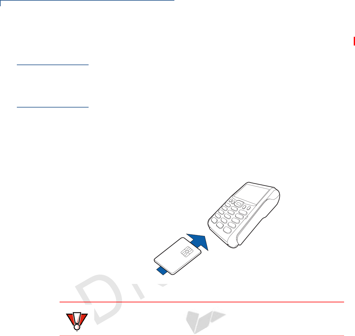
To Conduct a Smart
Card Transaction
1Position a smart card with the contacts facing upward (see illustration below).
2Insert the smart card into the smart card reader slot in a smooth, continuous
motion until it seats firmly.
3Remove the card only when the application indicates the transaction is
complete.
Figure 15 Inserting a Smart Card
CAUTION Do not remove the smart card in the card reader until the transaction is complete.
Premature card removal will invalidate the transaction.
TERMINAL SETUP
Using the Magnetic Card Reader
VX 675 INSTALLATION GUIDE 29
VERIFONE
CONFIDENTIAL
REVISION A
Using the
Magnetic Card
Reader
The VX 675 terminal supports credit/debit card transactions.
To Conduct a Credit
or Debit Card
Transaction
1Position a magnetic card with the stripe in the card reader and facing inward,
toward the keypad.
2To ensure a proper read of the magnetic swipe card, the user should insert the
magnetic card from the top of the unit, as shown in the following illustration.
3Swipe the card through the magnetic card reader.
Figure 16 Using the Magnetic Card Reader

TERMINAL SETUP
Using the Magnetic Card Reader
30 VX 675 INSTALLATION GUIDE
VERIFONE
CONFIDENTIAL
REVISION A
VX 675 INSTALLATION GUIDE 31
VERIFONE
CONFIDENTIAL
REVISION A
CHAPTER 3
Specifications
This chapter discusses power requirements, dimensions, and other specifications
of the VX 675 terminal.
Power
5V DC 1.0 A
DC Power Pack
UL, ITE listed, LPS power supply:
aInput rated: 100-240V AC, 50/60 Hz
bOutput rated: 5V DC 1.0 A
Barrel connector polarity:
Operating
Environment
•Temperature: 0°C to 50° C (32°F to 122° F)
•Relative humidity: 5% to 90%; non-condensing
External
Dimensions
•Length: 148 mm (5.8 in)
•Width: 78 mm (3.1 in)
•Depth: 42 mm (1.6 in)
n

SPECIFICATIONS
External Dimensions
32 VX 675 INSTALLATION GUIDE
VERIFONE
CONFIDENTIAL
REVISION A
VX 675 INSTALLATION GUIDE 33
VERIFONE
CONFIDENTIAL
REVISION A
CHAPTER 4
Maintenance
The VX 675 terminal and Base Stations have no user-serviceable parts.
Cleaning the
Terminal
To clean the terminal and Base Station, use a clean cloth slightly dampened with
water and a drop or two of mild soap. For stubborn stains, use alcohol or an
alcohol-based cleaner.
Terminal
Contacts
Gently swab the contacts with alcohol or contact cleaner to remove the dirt. It is
important that the exposed contacts of the VX 675 battery stay clean and unbent.
Smart Card
Reader
Do not attempt to clean the smart card reader. Doing so may void any warranty.
For smart card reader service, contact your VeriFone distributor or service
provider.
CAUTION Never use thinner, trichloroethylene, or ketone-based solvents – they may cause
deterioration of plastic or rubber parts.
Do not spray cleaners or other solutions directly onto the keypad or terminal
display.
CAUTION Avoid touching the contacts of the VX 675 battery and the recessed area on the
terminal. Finger oils tarnish contacts, causing bad connections. When operating
on battery power and experiencing a high occurrence of bad or incomplete data
transfers, clean the contacts.

MAINTENANCE
Smart Card Reader
34 VX 675 INSTALLATION GUIDE
VERIFONE
CONFIDENTIAL
REVISION A

VX 675 INSTALLATION GUIDE 35
VERIFONE
CONFIDENTIAL
REVISION A
CHAPTER 5
VeriFone Service and Support
For VX 675 terminal problems, contact your local VeriFone representative or
service provider.
For VX 675 product service and repair information:
•USA – VeriFone Service and Support Group, 1-800-VeriFone (837-4366),
Monday - Friday, 8 A.M. - 8 P.M., Eastern time
•International – Contact your VeriFone representative
Returning a
Terminal or
Smart Battery
for Service
Before returning a VX 675 terminal, smart battery, or Base Station to VeriFone,
you must obtain an MRA number. The following procedure describes how to
return one or more VX 675 terminals, smart batteries, or Base Stations for repair
or replacement (U.S. customers only).
To Return a Terminal
for Service
1Get the following information from the printed labels on the bottom of each
VX 675 terminal, smart battery, or sled module to be returned:
•Product ID, including the model and part number. For example, “VX 675”
and “M268-XXX-XX-XXX-2.”
•Serial number (S/N nnn-nnn-nnn)
2Obtain the MRA number(s) by completing one of the following:
aCall VeriFone toll-free within the United States at 1-800-VeriFone and
follow the automated menu options.
•Select the MRA option from the automated message. The MRA
department is open Monday to Friday, 8 A.M.–8 P.M., Eastern Time.
•Give the MRA representative the information you gathered in Step 1.
If the list of serial numbers is long, you can fax the list, along with the
information gathered in Step 1, to the MRA department at 727-953-
4172 (U.S.).
bAddress a fax to “VeriFone MRA Dept.” with the model and part number(s)
•Include a telephone number where you can be reached and your fax
number.
NOTE Customers outside the United States are advised to contact their local VeriFone
representative for assistance regarding service, return, or replacement of
terminals or batteries.

VERIFONE SERVICE AND SUPPORT
Returning a Terminal or Smart Battery for Service
36 VX 675 INSTALLATION GUIDE
VERIFONE
CONFIDENTIAL
REVISION A
cComplete the Inquiry Contact Form at http://www.verifone.com/aboutus/
contact/contact_form.cfm.
•Address the Subject box with to “VeriFone MRA Dept.”
•Reference the model and part number in the Note box.
3Describe the problem(s).
4Provide the shipping address where the repaired or replacement unit must be
returned.
5Keep a record of the following items:
•Assigned MRA number(s).
•VeriFone serial number assigned to the VX 675 terminal, smart battery, or
base station you are returning for service or repair (terminal serial
numbers are located on the bottom of the unit.
•Shipping documentation, such as air bill numbers used to trace the
shipment.
•Model(s) returned (model numbers are located on the VeriFone label on
the bottom of the VX 675 terminal).
NOTE One MRA number must be issued for each VX 675 terminal you return to
VeriFone, even if you are returning several of the same model.

VERIFONE SERVICE AND SUPPORT
Accessories and Documentation
VX 675 INSTALLATION GUIDE 37
VERIFONE
CONFIDENTIAL
REVISION A
Accessories and
Documentation
VeriFone produces the following accessories and documentation for the
VX 675 terminal. When ordering, please refer to the part number in the left
column.
•VeriFone online store at www.store.verifone.com
•USA – VeriFone Customer Development Center, 800-VeriFone (837-4366),
Monday - Friday, 7 A.M. - 8 P.M., Eastern time
•International – Contact your VeriFone representative
Power Pack
Contact your local VeriFone distributor to determine which power pack or
power cable fits your needs.
Printer Paper
VeriFone Cleaning
Kit
VPN PWR268-001-01-B DC Power Pack (Universal)
VPN PPR 000-000-00-A 25 mm (0.98 in) diameter, 57 mm (2.24 in) wide
VPN PPR 000-000-00-A 40 mm (1.57 in) diameter, 57 mm (2.24 in) wide
VPN 02746-01 Cleaning Kit

VERIFONE SERVICE AND SUPPORT
Accessories and Documentation
38 VX 675 INSTALLATION GUIDE
VERIFONE
CONFIDENTIAL
REVISION A
Documentation
VX 675 Certifications and Regulations Sheet VPN DOC265-001-EN-A
VX 675 Quick Installation Guide VPN DOC265-002-EN-A
VX 675 Reference Guide VPN DOC265-004-EN-A
Verix eVo Volume I: Operating System Programming
Manual
VPN DOC00301
Verix eVo Volume II: Operating System and
Communications Programmers Manual
VPN DOC00302
Verix eVo Volume III: Operating System Programming
Tools Reference Manual
VPN DOC00303

VX 675 INSTALLATION GUIDE 39
VERIFONE
CONFIDENTIAL
REVISION A
CHAPTER 6
Troubleshooting
Guidelines
The troubleshooting guidelines provided in the following section are included to
help you install and configure your VX 675 terminal successfully. Typical
examples of malfunction you may encounter while operating your VX 675 terminal
and steps you can take to resolve them are listed in this chapter.
If the problem persists even after performing the outlined guidelines or if the
problem is not described below, contact your local VeriFone representative for
assistance.
Terminal Does
Not Start
•Ensure that the smart battery charge state is not below the critically low level.
•Recharge or replace the smart battery.
•Ensure that you pressed the green ENTER/ON key for approximately 4
seconds, until the unit lights up.
Terminal Display
Does Not Show
Correct/
Readable Info
•Recharge or replace the battery.
•Connect the VX 675 terminal into a known-good power supply (if you have
one) to see if this clears the problem.
•If the problem persists, contact your local VeriFone representative for
assistance.
NOTE The VX 675 terminal comes equipped with tamper-evident labels. The VX 675 unit
contains no user serviceable parts. Do not, under any circumstance, attempt to
disassemble the terminal. Perform only those adjustments or repairs specified in
this guide. For all other services, contact your local VeriFone service provider.
Service conducted by parties other than authorized VeriFone representatives may
void any warranty.
CAUTION Use only a VeriFone-supplied power pack. Using an incorrectly rated power
supply may damage the terminal or cause it not to work as specified. Before
troubleshooting, ensure that the power supply being used to power the terminal
matches the requirements specified on the bottom of the terminal. (See
Specifications, for detailed power supply specifications.) Obtain the appropriately
rated power supply before continuing with troubleshooting.

TROUBLESHOOTING GUIDELINES
Smart Battery Does Not Charge
40 VX 675 INSTALLATION GUIDE
VERIFONE
CONFIDENTIAL
REVISION A
Smart Battery
Does Not Charge
The VX 675 smart battery must initially receive a full charge to ensure proper
operation.
Spare Battery in
Base Station
Does Not Charge
When the spare battery is installed in the base for charging, the Base LED will
flash amber if the battery is charging, or stay solid green if the battery is fully
charged. If the battery is not charged and the LED does not flash amber, check
the contacts on the battery and in the terminal base to make sure they are clean.
Also, try charging a known good battery to see if the problem is with the base or
with the battery. If the problem persists, contact your local VeriFone
representative.
Blank Display
When the VX 675 terminal display screen does not show correct or clearly
readable information:
•The battery pack may not be connected properly. Remove and reinstall the
battery pack.
•Check terminal power connection.
•Remove and reapply power to the terminal.
•If the problem persists, contact your local VeriFone service provider.
NOTE •Allow the VX 675 terminal to remain connected to the power pack for 6 hours
to ensure the battery receives a full charge.
•Li-ion batteries are not affected by shallow charging. Furthermore, when the
terminal has no external power source or battery the coin cell battery provides
power to the security circuit.
•Uninstalling the battery and unplugging the terminal power pack reduce the
life of the coin cell battery, which does not recharge and must be replaced if
drained.
•Conserve battery power by turning the VX 675 terminal off when not in use. If
the terminal will not be used for an extended period of time, keep the Li-ion
battery inserted in the terminal, and power up the terminal periodically to
check the battery charge. Do not let the battery charge fall below 10% for
extended periods of time as this may permanently diminish the battery
capacity. Recharge the battery by attaching the power cable to the terminal
and plugging the power pack into a wall outlet.
•The VX 675 terminal automatically shuts off when the smart battery reaches
the critically low charge state. If this occurs, the smart battery must recharge
a minimum of 1/2 hour before it can power the terminal. It may take several
recharge attempts to reset the safety circuit when charging a smart battery
that has been discharged below this critical state.

TROUBLESHOOTING GUIDELINES
Terminal Does Not Dial Out
VX 675 INSTALLATION GUIDE 41
VERIFONE
CONFIDENTIAL
REVISION A
Terminal Does
Not Dial Out
If the terminal does not dial out:
•Check the telephone line connections.
•Check that the telephone line is working by plugging it into a working
telephone and listening for a dial tone.
•Replace the telephone cable that connects the terminal with a cable you know
is working correctly.
•If the problem persists, contact your local VeriFone service provider.
Printer Does Not
Print
If the printer does not work properly:
•Make sure the battery is properly installed in the terminal. The printer will not
print if there is no battery in the terminal.
•Check battery status or terminal power connection. The printer will not print if
there is an insufficient charge remaining in the battery to complete the print
operation.
•Check if the printer is out of paper (slow red blinking light) and that the roll is
properly installed. Open the paper roll cover and install a new roll of printer
paper or ensure that the roll is feeding correctly. A solid red indicator light
indicates a printer error.
•Verify that the printer door is properly latched.
•If the problem persists, contact your VeriFone distributor or service provider.
Printer Paper
Jam
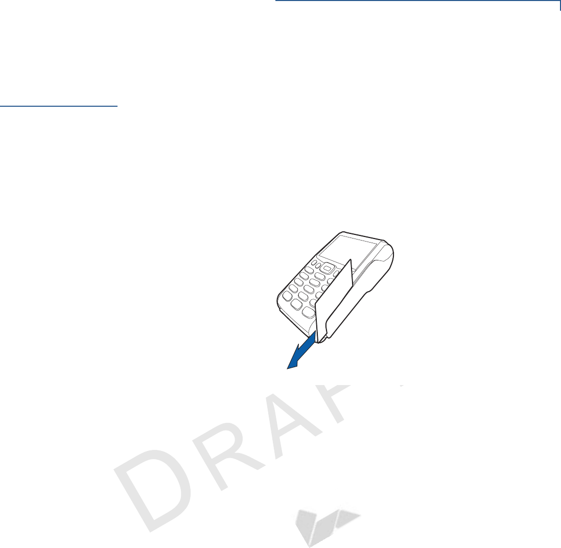
If paper jams inside the printer:
•Press the button at the bottom of the terminal to unlatch the paper roll cover,
then open the cover.
•Remove the damaged paper from the paper roll and clear the feed
mechanism.
•Install a roll of printer paper, as described in Installing the Paper Roll.
•If the problem persists, it may be due to poor paper quality. Install a new roll of
higher-quality paper.
WARNING Poor-quality paper may jam the printer. To order high-quality VeriFone paper,
refer to Accessories and Documentation.

TROUBLESHOOTING GUIDELINES
Keypad Does Not Respond
42 VX 675 INSTALLATION GUIDE
VERIFONE
CONFIDENTIAL
REVISION A
Keypad Does
Not Respond
If the keypad does not respond properly:
•Check the terminal display. If it displays the wrong character or nothing at all
when you press a key, follow the steps outlined in Transactions Fail to
Process.
•If pressing a function key does not perform the expected action, refer to the
user documentation for that application to ensure you are entering data
correctly.
•If the problem persists, contact your local VeriFone representative.
Transactions
Fail to Process
There are several reasons why the terminal may not be processing transactions.
Use the following steps to troubleshoot failures.
Check the Magnetic Card Reader
•Perform a test transaction using one or more different magnetic stripe cards to
ensure the problem is not a defective card.
•Ensure that you are swiping cards properly. With the VX 675 card reader, the
black magnetic stripe on the card should face down and inward, toward the
keypad and must be inserted from the top of the terminal (see Figure 16).
•Process a transaction manually, using the keypad instead of the card reader. If
the manual transaction works, the problem may be a defective card reader.
•Contact your VeriFone distributor or service provider.
•If the manual transaction does not work, proceed to Check the Telephone
Line.
Check the Smart Card Reader
•Perform a test transaction using several different smart cards to ensure the
problem is not a defective card.
•Ensure that the card is inserted correctly and that the card is not removed
prematurely.
•Contact your VeriFone distributor or service provider.
•If the manual transaction does not process, proceed to Check the Telephone
Line.

TROUBLESHOOTING GUIDELINES
Transactions Fail to Process
VX 675 INSTALLATION GUIDE 43
VERIFONE
CONFIDENTIAL
REVISION A
Check the Telephone Line
•Disconnect the telephone line from the VX 675 terminal and connect it to a
working telephone to check for a dial tone. If there is no dial tone, replace the
telephone cable.
•If the problem appears to be with the telephone line, check with the party you
are trying to call to see if their system is operational. If they are not
experiencing difficulties with their line, contact the telephone company and
have your line checked.
•If the telephone line works, contact your local VeriFone representative for
assistance.

TROUBLESHOOTING GUIDELINES
Transactions Fail to Process
44 VX 675 INSTALLATION GUIDE
VERIFONE
CONFIDENTIAL
REVISION A
FCC Regulations:
This device complies with part 15 of the FCC Rules. Operation is subject to the following
two conditions: (1) This device may not cause harmful interference, and (2) this device must
accept any interference received, including interference that may cause undesired operation.
This device has been tested and found to comply with the limits for a Class B digital device,
pursuant to Part 15 of the FCC Rules. These limits are designed to provide reasonable
protection against harmful interference in a residential installation. This equipment generates
uses and can radiate radio frequency energy and, if not installed and used in accordance with
the instructions, may cause harmful interference to radio communications. However, there is
no guarantee that interference will not occur in a particular installation If this equipment does
cause harmful interference to radio or television reception, which can be determined by
turning the equipment off and on, the user is encouraged to try to correct the interference by
one or more of the following measures:
-Reorient or relocate the receiving antenna.
-Increase the separation between the equipment and receiver.
-Connect the equipment into an outlet on a circuit different from that to which the receiver is
connected.
-Consult the dealer or an experienced radio/TV technician for help.
FCC Caution: Any changes or modifications not expressly approved by the party responsible
for compliance could void the user's authority to operate this equipment.
This transmitter must not be co-located or operating in conjunction with any other antenna or
transmitter.

4
44
4RF Exposure Information (SAR)
This device meets the government’s requirements for exposure to radio waves.
This device is designed and manufactured not to exceed the emission limits for exposure to
radio frequency (RF) energy set by the Federal Communications Commission of the U.S.
Government.
The exposure standard for wireless device employs a unit of measurement known as the
Specific Absorption Rate, or SAR. The SAR limit set by the FCC is 1.6W/kg. *Tests for
SAR are conducted using standard operating positions accepted by the FCC with the device
transmitting at its highest certified power level in all tested frequency bands. Although the
SAR is determined at the highest certified power level, the actual SAR level of the device
while operating can be well below the maximum value. This is because the device is
designed to operate at multiple power levels so as to use only the poser required to reach the
network. In general, the closer you are to a wireless base station antenna, the lower the
power output.
The highest SAR value for the device as reported to the FCC when tested for use at the body is
0.694 W/kg and when worn on the body, as described in this user guide, is 0.694 W/kg
(Body-worn measurements differ among device models, depending upon available
accessories and FCC requirements.)
While there may be differences between the SAR levels of various devices and at various
positions, they all meet the government requirement.
The FCC has granted an Equipment Authorization for this model device with all reported
SAR levels evaluated as in compliance with the FCC RF exposure guidelines. SAR
information on this model device is on file with the FCC and can be found under the Display
Grant section of www.fcc.gov/oet/ea/fccid after searching on FCC ID:
B32VX675GPRSCTLS.
For body worn operation, this device has been tested and meets the FCC RF exposure
guidelines for use with an accessory that contains no metal and the positions the handset a
minimum of 1.5 cm from the body. Use of other accessories may not ensure compliance
with FCC RF exposure guidelines. If you do no t use a body-worn accessory and are not
holding the device at the ear, position the handset a minimum of 1.5 cm from your body when
the phone is switched on.
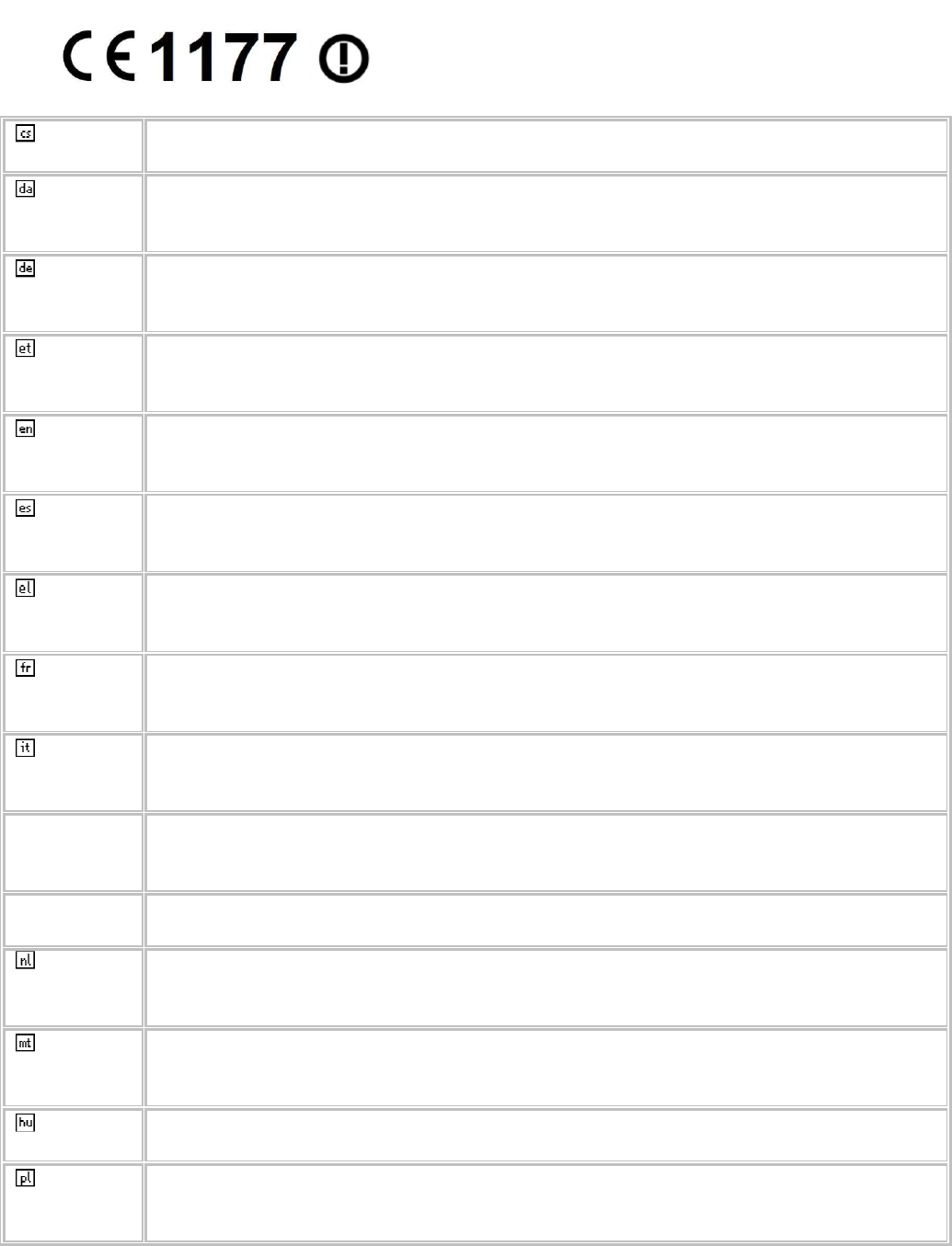
Česky
[Czech]
[Jméno výrobce] tímto prohlašuje, že tento [typ zařízení] je ve shodě se
základními požadavky a dalšími příslušnými ustanoveními směrnice 1999/5/ES.
Dansk
[Danish]
Undertegnede [fabrikantens navn] erklærer herved, at følgende udstyr
[udstyrets typebetegnelse] overholder de væsentlige krav og øvrige relevante
krav i direktiv 1999/5/EF.
Deutsch
[German]
Hiermit erklärt [Name des Herstellers], dass sich das Gerät [Gerätetyp] in
Übereinstimmung mit den grundlegenden Anforderungen und den übrigen
einschlägigen Bestimmungen der Richtlinie 1999/5/EG befindet.
Eesti
[Estonian]
Käesolevaga kinnitab [tootja nimi = name of manufacturer] seadme [seadme
tüüp = type of equipment] vastavust direktiivi 1999/5/EÜ põhinõuetele ja
nimetatud direktiivist tulenevatele teistele asjakohastele sätetele.
English Hereby, [name of manufacturer], declares that this [type of equipment] is in
compliance with the essential requirements and other relevant provisions of
Directive 1999/5/EC.
Español
[Spanish]
Por medio de la presente [nombre del fabricante] declara que el [clase de
equipo] cumple con los requisitos esenciales y cualesquiera otras disposiciones
aplicables o exigibles de la Directiva 1999/5/CE.
Ελληνική
[Greek]
ΜΕ ΤΗΝ ΠΑΡΟΥΣΑ [name of manufacturer] ∆ΗΛΩΝΕΙ ΟΤΙ [type of equipment]
ΣΥΜΜΟΡΦΩΝΕΤΑΙ ΠΡΟΣ ΤΙΣ ΟΥΣΙΩ∆ΕΙΣ ΑΠΑΙΤΗΣΕΙΣ ΚΑΙ ΤΙΣ ΛΟΙΠΕΣ ΣΧΕΤΙΚΕΣ
∆ΙΑΤΑΞΕΙΣ ΤΗΣ Ο∆ΗΓΙΑΣ 1999/5/ΕΚ.
Français
[French]
Par la présente [nom du fabricant] déclare que l'appareil [type d'appareil] est
conforme aux exigences essentielles et aux autres dispositions pertinentes de la
directive 1999/5/CE.
Italiano
[Italian]
Con la presente [nome del costruttore] dichiara che questo [tipo di
apparecchio] è conforme ai requisiti essenziali ed alle altre disposizioni pertinenti
stabilite dalla direttiva 1999/5/CE.
Latviski
[Latvian]
Ar šo [name of manufacturer / izgatavotāja nosaukums] deklarē, ka [type of
equipment / iekārtas tips] atbilst Direktīvas 1999/5/EK būtiskajām prasībām un
citiem ar to saistītajiem noteikumiem.
Lietuvių
[Lithuanian]
Šiuo [manufacturer name] deklaruoja, kad šis [equipment type] atitinka esminius
reikalavimus ir kitas 1999/5/EB Direktyvos nuostatas.
Nederlands
[Dutch]
Hierbij verklaart [naam van de fabrikant] dat het toestel [type van toestel] in
overeenstemming is met de essentiële eisen en de andere relevante
bepalingen van richtlijn 1999/5/EG.
Malti
[Maltese]
Hawnhekk, [isem tal-manifattur], jiddikjara li dan [il-mudel tal-prodott]
jikkonforma mal-ħtiġijiet essenzjali u ma provvedimenti oħrajn relevanti li hemm
fid-Dirrettiva 1999/5/EC.
Magyar
[Hungarian]
Alulírott, [gyártó neve] nyilatkozom, hogy a [... típus] megfelel a vonatkozó
alapvetõ követelményeknek és az 1999/5/EC irányelv egyéb elõírásainak.
Polski
[Polish]
Niniejszym [nazwa producenta] oświadcza, że [nazwa wyrobu] jest zgodny z
zasadniczymi wymogami oraz pozostałymi stosownymi postanowieniami
Dyrektywy 1999/5/EC.

Português
[Portuguese
]
[Nome do fabricante] declara que este [tipo de equipamento] está conforme
com os requisitos essenciais e outras disposições da Directiva 1999/5/CE.
Slovensko
[Slovenian]
[Ime proizvajalca] izjavlja, da je ta [tip opreme] v skladu z bistvenimi zahtevami
in ostalimi relevantnimi določili direktive 1999/5/ES.
Slovensky
[Slovak]
[Meno výrobcu] týmto vyhlasuje, že [typ zariadenia] spĺňa základné požiadavky
a všetky príslušné ustanovenia Smernice 1999/5/ES.
Suomi
[Finnish]
[Valmistaja = manufacturer] vakuuttaa täten että [type of equipment = laitteen
tyyppimerkintä] tyyppinen laite on direktiivin 1999/5/EY oleellisten vaatimusten ja
sitä koskevien direktiivin muiden ehtojen mukainen.
Svenska
[Swedish]
Härmed intygar [företag] att denna [utrustningstyp] står I överensstämmelse
med de väsentliga egenskapskrav och övriga relevanta bestämmelser som
framgår av direktiv 1999/5/EG.

VX 675 INSTALLATION GUIDE 45
VERIFONE
CONFIDENTIAL
REVISION A.2
INDEX
A
accessories 37
documentation 38
power packs 37
VeriFone cleaning kit 37
B
Base Station 25
batteries
See also smart battery
C
cleaning kit 37
connection ports 17
contact VeriFone 35
D
dial out problems
troubleshooting 41
displays
troubleshooting 39, 40
documentation 37
acronym definitions 7
conventions 6
ordering 38
E
electrical considerations 14
environmental factors 14
H
HDMI 7
I
installation 9
connecting the terminal power pack 22
terminal location 14
unpacking the shipping carton 15
K
keypads
troubleshooting 42
M
maintenance
cleaning the terminal 33
cleaning the terminal contacts 33
P
paper jams
troubleshooting 41
paper rolls
for thermal printers 18, 41
installation 18
power adapter cables 17
power packs
AC version 37
connecting 22
DC version 37
ordering 37
printers
troubleshooting 41
S
SIM cards
for GSM models 20
smart battery
battery life 24
charging 23
conserving power 21
disposal 24
features 21
recharging 24
troubleshooting 40
specifications
DC power pack 31
power 31
standard Base Station 25

INDEX
T
46 VX 675 INSTALLATION GUIDE
ERIONE
ONFIDENIA
T
technical support
contacting VeriFone 35
terminal features
general 16
terminals
accessories 37
benefits 10
cleaning 33
documentation 37
electrical considerations 14
environmental factors 14
features 16
repair 35
replacement 35
service and support 35
troubleshooting 39, 40
thermal printer paper
storage 18
thermal printers
about the thermal printer paper 18, 41
paper jams 41
troubleshooting 41
transactions
smart cards 28
troubleshooting
batteries 40
displays 39, 40
guidelines 39
keypads 42
printers 41
terminal transactions 42
terminals 39, 41