Verifone VX675WIFIBT Point of Sale Terminal User Manual
VeriFone Inc Point of Sale Terminal
Verifone >
User Manual.pdf
VeriFone Part Number DOC265-003-EN-F, Revision F
VX 675
Installation Guide
3
DEF
2
ABC
1
QZ.
4
GHI
7
PRS
*
5
JKL
8
TUV
0
-SP
X
6
MNO
9
WXY
#
’ ”
’
All rights reserved. No part of the contents of this document may be reproduced or transmitted in any form without the written
permission of VeriFone, Inc.
The information contained in this document is subject to change without notice. Although VeriFone has attempted to ensure the
accuracy of the contents of this document, this document may include errors or omissions. The examples and sample programs are
for illustration only and may not be suited for your purpose. You should verify the applicability of any example or sample program
before placing the software into productive use. This document, including without limitation the examples and software programs, is
supplied “As-Is.”
VeriFone, Inc.
2099 Gateway Place, Suite 600
San Jose, CA, 95110 USA
1-800-VERIFONE
www.verifone.com
VeriFone Part Number DOC265-003-EN-F, Revision F
VX 675 Installation Guide
© 2013 VeriFone, Inc.
VeriFone, the VeriFone logo, Omni, VeriCentre, and Verix are registered trademarks of VeriFone. Other brand names or trademarks
associated with VeriFone’s products and services are trademarks of VeriFone, Inc.
All other brand names and trademarks appearing in this manual are the property of their respective holders.
Comments? Please e-mail all comments on this document to your local VeriFone Support Team.

VX 675 INSTALLATION GUIDE 3
CONTENTS
PREFACE . . . . . . . . . . . . . . . . . . . . . . . . . . . . . . . . . . . . . . . 5
Audience. . . . . . . . . . . . . . . . . . . . . . . . . . . . . . . . . . . . . . . . . . . . . . . . . . . . . . . . 5
Organization . . . . . . . . . . . . . . . . . . . . . . . . . . . . . . . . . . . . . . . . . . . . . . . . . . . . . 5
Related Documentation . . . . . . . . . . . . . . . . . . . . . . . . . . . . . . . . . . . . . . . . . . . . 5
Conventions and Acronyms . . . . . . . . . . . . . . . . . . . . . . . . . . . . . . . . . . . . . . . . . 6
Document Conventions. . . . . . . . . . . . . . . . . . . . . . . . . . . . . . . . . . . . . . . . . . 6
Acronym Definitions . . . . . . . . . . . . . . . . . . . . . . . . . . . . . . . . . . . . . . . . . . . . 7
CHAPTER 1
Terminal Overview Features at a Glance . . . . . . . . . . . . . . . . . . . . . . . . . . . . . . . . . . . . . . . . . . . . . 10
Features and Benefits . . . . . . . . . . . . . . . . . . . . . . . . . . . . . . . . . . . . . . . . . . . . 10
Exceptional Ease of Use. . . . . . . . . . . . . . . . . . . . . . . . . . . . . . . . . . . . . . . . 10
Performance and Durability . . . . . . . . . . . . . . . . . . . . . . . . . . . . . . . . . . . . . 10
Security. . . . . . . . . . . . . . . . . . . . . . . . . . . . . . . . . . . . . . . . . . . . . . . . . . . . . 11
Communication Technology . . . . . . . . . . . . . . . . . . . . . . . . . . . . . . . . . . . . . 11
CHAPTER 2
Terminal Setup Selecting Terminal Location . . . . . . . . . . . . . . . . . . . . . . . . . . . . . . . . . . . . . . . . 14
Environmental Factors . . . . . . . . . . . . . . . . . . . . . . . . . . . . . . . . . . . . . . . . . 14
Electrical Considerations . . . . . . . . . . . . . . . . . . . . . . . . . . . . . . . . . . . . . . . 14
Bluetooth Base Considerations. . . . . . . . . . . . . . . . . . . . . . . . . . . . . . . . . . . 14
Unpacking the Shipping Carton . . . . . . . . . . . . . . . . . . . . . . . . . . . . . . . . . . . . . 15
Examining Terminal Features. . . . . . . . . . . . . . . . . . . . . . . . . . . . . . . . . . . . . . . 16
Front Panel . . . . . . . . . . . . . . . . . . . . . . . . . . . . . . . . . . . . . . . . . . . . . . . . . . 16
Examining Connection Port . . . . . . . . . . . . . . . . . . . . . . . . . . . . . . . . . . . . . . . . 17
3G Support . . . . . . . . . . . . . . . . . . . . . . . . . . . . . . . . . . . . . . . . . . . . . . . . . . . . . 17
WiFi Bluetooth Support. . . . . . . . . . . . . . . . . . . . . . . . . . . . . . . . . . . . . . . . . . . . 17
Installing the Paper Roll . . . . . . . . . . . . . . . . . . . . . . . . . . . . . . . . . . . . . . . . . . . 18
Installing the SIM Card . . . . . . . . . . . . . . . . . . . . . . . . . . . . . . . . . . . . . . . . . . . . 20
Dual SIM . . . . . . . . . . . . . . . . . . . . . . . . . . . . . . . . . . . . . . . . . . . . . . . . . . . . 21
Installing and Replacing SD Card. . . . . . . . . . . . . . . . . . . . . . . . . . . . . . . . . . . . 21
Using the Battery . . . . . . . . . . . . . . . . . . . . . . . . . . . . . . . . . . . . . . . . . . . . . . . . 21
Battery Features . . . . . . . . . . . . . . . . . . . . . . . . . . . . . . . . . . . . . . . . . . . . . . 21
Battery Behavior (No Power Pack). . . . . . . . . . . . . . . . . . . . . . . . . . . . . . . . . . . 22
Manual Startup . . . . . . . . . . . . . . . . . . . . . . . . . . . . . . . . . . . . . . . . . . . . . . . 22
Manual Shutdown . . . . . . . . . . . . . . . . . . . . . . . . . . . . . . . . . . . . . . . . . . . . . 22
Connecting the Terminal Power Pack . . . . . . . . . . . . . . . . . . . . . . . . . . . . . . . . 23
Charging the Battery. . . . . . . . . . . . . . . . . . . . . . . . . . . . . . . . . . . . . . . . . . . . . . 24
Battery Life . . . . . . . . . . . . . . . . . . . . . . . . . . . . . . . . . . . . . . . . . . . . . . . . . . 24
VX 675 Base Stations. . . . . . . . . . . . . . . . . . . . . . . . . . . . . . . . . . . . . . . . . . . . . 24
USB Base . . . . . . . . . . . . . . . . . . . . . . . . . . . . . . . . . . . . . . . . . . . . . . . . . . . 25
Full-Feature Base . . . . . . . . . . . . . . . . . . . . . . . . . . . . . . . . . . . . . . . . . . . . . 25
Bluetooth Base . . . . . . . . . . . . . . . . . . . . . . . . . . . . . . . . . . . . . . . . . . . . . . . 26
Powering Up the Base . . . . . . . . . . . . . . . . . . . . . . . . . . . . . . . . . . . . . . . . . . . . 26
Docking the Terminal on the Base . . . . . . . . . . . . . . . . . . . . . . . . . . . . . . . . . . . 27
Undocking the Terminal from the Base . . . . . . . . . . . . . . . . . . . . . . . . . . . . . . . 27

CONTENTS
4VX 675 INSTALLATION GUIDE
Connecting to USB Host. . . . . . . . . . . . . . . . . . . . . . . . . . . . . . . . . . . . . . . . . . . 28
Conducting a Bluetooth Transaction . . . . . . . . . . . . . . . . . . . . . . . . . . . . . . . . . 28
Conducting Wireless Transactions. . . . . . . . . . . . . . . . . . . . . . . . . . . . . . . . . . . 29
Conducting Smart Card Transactions . . . . . . . . . . . . . . . . . . . . . . . . . . . . . . . . 29
Using the Magnetic Card Reader . . . . . . . . . . . . . . . . . . . . . . . . . . . . . . . . . . . . 30
ECR (Fiscal Module) Support. . . . . . . . . . . . . . . . . . . . . . . . . . . . . . . . . . . . . . . 30
Customer Display . . . . . . . . . . . . . . . . . . . . . . . . . . . . . . . . . . . . . . . . . . . . . 31
CHAPTER 3
Specifications Power . . . . . . . . . . . . . . . . . . . . . . . . . . . . . . . . . . . . . . . . . . . . . . . . . . . . . . . . . 33
DC Power Pack . . . . . . . . . . . . . . . . . . . . . . . . . . . . . . . . . . . . . . . . . . . . . . . . . 33
Temperature. . . . . . . . . . . . . . . . . . . . . . . . . . . . . . . . . . . . . . . . . . . . . . . . . . . . 33
External Dimensions. . . . . . . . . . . . . . . . . . . . . . . . . . . . . . . . . . . . . . . . . . . . . . 33
CHAPTER 4
Maintenance Cleaning the Terminal . . . . . . . . . . . . . . . . . . . . . . . . . . . . . . . . . . . . . . . . . . . . 35
Terminal Contacts . . . . . . . . . . . . . . . . . . . . . . . . . . . . . . . . . . . . . . . . . . . . . . . 35
Smart Card Reader . . . . . . . . . . . . . . . . . . . . . . . . . . . . . . . . . . . . . . . . . . . . . . 35
CHAPTER 5
VeriFone Service
and Support Returning a Terminal for Service . . . . . . . . . . . . . . . . . . . . . . . . . . . . . . . . . . . . 37
Accessories and Documentation . . . . . . . . . . . . . . . . . . . . . . . . . . . . . . . . . . . . 38
Power Pack. . . . . . . . . . . . . . . . . . . . . . . . . . . . . . . . . . . . . . . . . . . . . . . . . . 38
Printer Paper. . . . . . . . . . . . . . . . . . . . . . . . . . . . . . . . . . . . . . . . . . . . . . . . . 38
VeriFone Cleaning Kit. . . . . . . . . . . . . . . . . . . . . . . . . . . . . . . . . . . . . . . . . . 38
Micro-USB Cable . . . . . . . . . . . . . . . . . . . . . . . . . . . . . . . . . . . . . . . . . . . . . 39
Documentation . . . . . . . . . . . . . . . . . . . . . . . . . . . . . . . . . . . . . . . . . . . . . . . 39
CHAPTER 6
Troubleshooting
Guidelines Terminal Does Not Start. . . . . . . . . . . . . . . . . . . . . . . . . . . . . . . . . . . . . . . . . . . 41
Terminal Display Does Not Show Correct/Readable Info. . . . . . . . . . . . . . . . . . 41
Battery Does Not Charge . . . . . . . . . . . . . . . . . . . . . . . . . . . . . . . . . . . . . . . . . . 42
Blank Display . . . . . . . . . . . . . . . . . . . . . . . . . . . . . . . . . . . . . . . . . . . . . . . . . . . 42
Printer Does Not Print. . . . . . . . . . . . . . . . . . . . . . . . . . . . . . . . . . . . . . . . . . . . . 42
Printer Paper Jam. . . . . . . . . . . . . . . . . . . . . . . . . . . . . . . . . . . . . . . . . . . . . . . . 43
Keypad Does Not Respond . . . . . . . . . . . . . . . . . . . . . . . . . . . . . . . . . . . . . . . . 43
Transactions Fail to Process . . . . . . . . . . . . . . . . . . . . . . . . . . . . . . . . . . . . . . . 43

VX 675 INSTALLATION GUIDE 5
PREFACE
This guide is your primary source of information for setting up and installing the
VX 675 terminal.
Audience
This guide is useful for anyone installing and configuring a VX 675 terminal. Basic
descriptions of the terminal features are also provided.
Organization
This guide is organized as follows:
Chapter 1, Terminal Overview. Provides an overview of the VX 675 terminal.
Chapter 2, Terminal Setup. Explains how to set up and install the VX 675 terminal.
Provides information on how to select a location, establish power, and how to
configure optional peripheral devices.
Chapter 3, Specifications. Discusses power requirements and dimensions of the
VX 675 terminal.
Chapter 4, Maintenance. Explains how to maintain your VX 675 terminal.
Chapter 5, VeriFone Service and Support. Provides information on contacting
your local VeriFone representative or service provider, and information on how to
order accessories or documentation from VeriFone.
Chapter 6, Troubleshooting Guidelines. Provides troubleshooting guidelines,
should you encounter a problem in terminal installation and configuration.
Related
Documentation
To learn more about the VX 675 terminal, refer to the following set of documents:
VX 675 Certifications and Regulations Sheet VPN DOC265-001-EN
VX 675 Quick Installation Guide VPN DOC265-002-EN
VX 675 Reference Guide VPN DOC265-004-EN
Verix eVo Volume I: Operating System
Programmers Manual
VPN DOC00301
Verix eVo Volume II: Operating System and
Communications Programmers Manual
VPN DOC00302
VX 675 USB Only Base Quick Installation Guide DOC265-025-EN
VX 675 Full-Feature Base Quick Installation DOC265-026-EN
VX 675 ECR Quick Installation Guide DOC265-028-EN
PREFACE
Conventions and Acronyms
6VX 675 INSTALLATION GUIDE
Conventions and
Acronyms
This section describes the conventions and acronyms used in this guide.
Document
Conventions
Various conventions are used to help you quickly identify special formatting. Table
1 describes these conventions and provides examples of their use.
Table 1 Document Conventions
Convention Meaning Example
Blue Text in blue indicates terms
that are cross referenced.
See Conventions and Acronyms.
Italics Italic typeface indicates
book titles or emphasis.
You must install a roll of thermal-
sensitive paper in the printer.
Courier The courier type face is
used while specifying
onscreen text, such as text
that you would enter at a
command prompt, or to
provide an URL.
http://www.verifone.com
The pencil icon is used to
highlight important
information.
RS-232-type devices do not work
with the PINpad port.
The caution symbol
indicates possible hardware
or software failure, or loss
of data.
The terminal is not waterproof or
dustproof, and is intended for indoor
use only.
The lightning symbol is
used as a warning when
bodily injury might occur.
Due to risk of shock do not use the
terminal near water.
NOTE
CAUTION
WARNING

PREFACE
Conventions and Acronyms
VX 675 INSTALLATION GUIDE 7
Acronym Definitions
Various acronyms are used in place of the full definition. Table 2 presents
acronyms and their definitions.
Table 2 Acronym Definitions
Acronym Definitions
AC Alternating Current
CDMA Code Division Multiple Access
EMV Joint Europay, MasterCard and Visa Standard
GPRS General Packet Radio Service
GSM Global System for Mobile Communication
ITP Internal Thermal Printer
LCD Liquid Crystal Display
LED Light Emitting Diode
MRA Merchandise Return Authorization
MSAM Micromodule-Size Security Access Module
PED PIN Entry Device
PIN Personal Identification Number
POS Point-of-Sale
QVGA Quarter Video Graphics Array
RJ45 Registered Jack 45
RS-232 Recommended Standard 232
R-UIM Removable User Identity Module
SAM Security Access Module
SD Secure Digital
SIM Subscriber Identity Module
TFT Thin Film Transistor
UART Universal Asynchronous Transmitter/Receiver
USB Universal Serial Bus
VPN VeriFone Part Number

PREFACE
Conventions and Acronyms
8VX 675 INSTALLATION GUIDE
VX 675 INSTALLATION GUIDE 9
CHAPTER 1
Terminal Overview
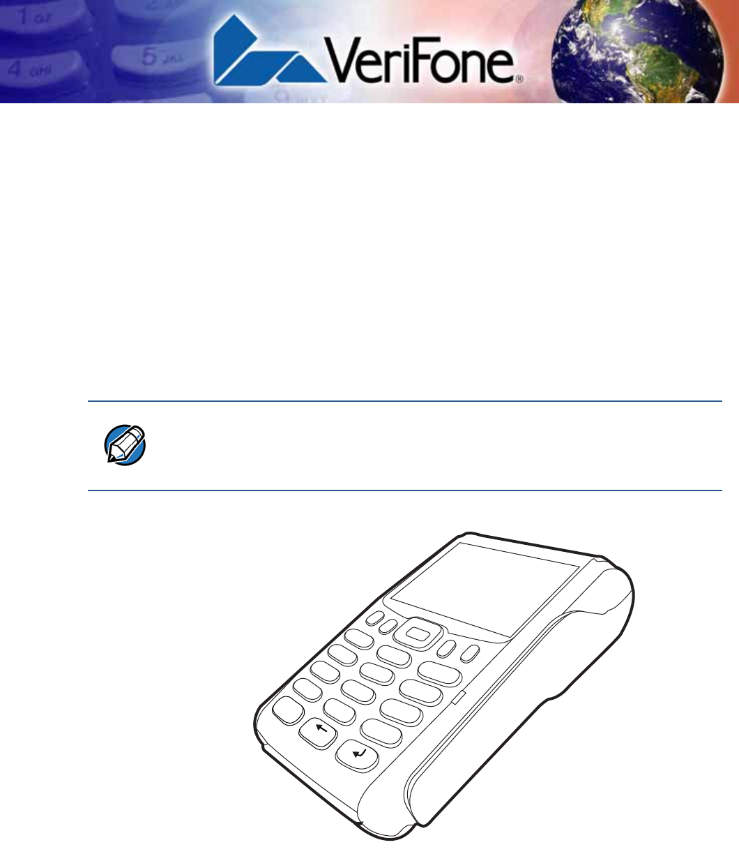
This chapter provides a brief description of the VX 675 terminal. This terminal
features a color screen display, fast processor, abundant memory, and PCI 3.0
security.
The VX 675 terminal is a portable, battery-powered device designed to fit
comfortably during handheld consumer-facing applications. It features a 2.8” TFT
LCD display and a backlit spill-resistant keypad. It supports GPRS, 3G, Bluetooth,
and WiFi communications technology.
Figure 1 The VX 675 Terminal
NOTE
VeriFone ships variants of the VX 675 terminal for different markets. Your terminal
may have a different configuration—it may or may not have dual SIM slots or the
optional removable SD flash memory, among others. VX 675 with fiscal ECR
functionality is specific only to Turkey market.
3
DEF
2
ABC
1
QZ.
4
GHI
7
PRS
*
5
JKL
8
TUV
0
-SP
X
6
MNO
9
WXY
#
’ ”
’

TERMINAL OVERVIEW
Features at a Glance
10 VX 675 INSTALLATION GUIDE
Features at a
Glance
The following are the features of VX 675:
Features and
Benefits
VX 675 terminals provide the right combination of features and functions including
a triple-track magnetic stripe card reader, smart card reader, integrated PIN pad,
color screen display, and a quiet yet fast internal thermal printer (ITP).
Exceptional Ease of
Use
•Lightweight, tapered design, compact, stylish and the ergonomic balance
allows convenient terminal hand-off to the consumer for PIN entry or other
input.
•2.8” TFT LCD display for boundless application possibilities and easy
readability under various lighting conditions.
•Large, blue backlit keys provide tactile response to simplify usage and
minimize finger slips.
•25 mm (for GPRS model only) and 40 mm diameter paper roll support with a
trouble-free, drop-in, “clam shell” loading and dual tear bar that allow receipts
to be torn in any direction.
•Quiet and fast integrated thermal printer.
•Vertical magnetic stripe card reader with an extended blade for optimal card
reading.
Performance and
Durability
•Fast transactions due to powerful 400 MHz ARM11 processor.
•High-capacity 3.6V 2200 mAh Li-ion battery. 3G and WiFi-BT support 3.7V
2450 mAh Li-ion battery pack.
•Base for drop-and-go charging.
•Rounded corners and drop resistant to 3 feet on concrete floor to minimize
breakage.
•400 MHz ARM11 RISC processor
delivers power and usability in a
convenient “hand-over” design.
•Securely supports and runs payment
and value-added applications along
with signature capture.
•Multi-application operating
environment.
•Offers unsurpassed performance on
EMV smart card transactions
•Advanced memory architecture to
meet tomorrow’s needs with support
for 192 MB.
•Max UI design provides large 2.8” color
LCD display, and large blue backlit keys
for easier viewing.
•Backward compatibility with VeriFone
solutions help reduces development
costs.
•Adds vibrant color screen to the
smallest purpose-built wireless payment
device.
•Drop-resistant design minimizes
breakage.
•Multiple connectivity options.
•32-bit processing and multi-tasking
capabilities.
•Spill-resistant design forces liquid down
and off the front of the terminal.
•Security architecture exceeds
specifications for PCI-PED and
sophisticated file authentication.

TERMINAL OVERVIEW
Features and Benefits
VX 675 INSTALLATION GUIDE 11
•192 MB of memory with optional removable flash memory.
Security
•PCI PED 3.0 approved for debit and other PIN-based transactions.
•EMV Level 1 and 2 Type Approval.
•Tamper-resistant construction, SSL protocols, and VeriShield file
authentication.
Communication
Technology
•VX 675 GPRS and 3G: Long-range wireless payment for retailers that have no
physical location limitations.
•VX 675 WiFi: Ideal for retailers that need multiple wireless devices and have
existing IP infrastructure.
•VX 675 Bluetooth: Simple, plug-and-play installation for locations that need
short-range wireless capability.

TERMINAL OVERVIEW
Features and Benefits
12 VX 675 INSTALLATION GUIDE

VX 675 INSTALLATION GUIDE 13
CHAPTER 2
Terminal Setup
This chapter describes terminal setup procedures. You will learn about:
•Selecting Terminal Location
•Unpacking the Shipping Carton
•Examining Terminal Features
•Examining Connection Port
•Installing the Paper Roll
•Installing the SIM Card
•Installing and Replacing SD Card
•Using the Battery
•Battery Behavior (No Power Pack)
•Charging the Battery
•Connecting the Terminal Power Pack
•VX 675 Base Stations
•Powering Up the Base
•Docking the Terminal on the Base
•Undocking the Terminal from the Base
•Connecting to USB Host
•Conducting a Bluetooth Transaction
•Conducting Wireless Transactions
•Conducting Smart Card Transactions
•Using the Magnetic Card Reader
•ECR (Fiscal Module) Support

TERMINAL SETUP
Selecting Terminal Location
14 VX 675 INSTALLATION GUIDE
Selecting
Terminal
Location
Use the following guidelines when selecting a location for your VX 675 terminal.
Environmental
Factors
•The VX 675 unit is a portable terminal. Select a flat support surface, such as a
countertop or table, to keep the terminal safe in between uses.
•Do not use the terminal where there is high heat, dust, humidity, moisture, or
caustic chemicals or oils.
•Keep the terminal away from direct sunlight and anything that radiates heat,
such as a stove or motor.
•Do not use the terminal outdoors.
Electrical
Considerations
•Avoid using this product during electrical storms.
•Avoid locations near electrical appliances or other devices that cause
excessive voltage fluctuations or emit electrical noise (for example, air
conditioners, electric motors, neon signs, high-frequency or magnetic security
devices, or computer equipment).
•Do not use the terminal near water or in moist conditions.
Bluetooth Base
Considerations
The BT base requires the following:
•A power source within two meters.
•A telephone socket within three meters (for PSTN version)
•A location with minimal obstruction for communication with terminals.
•Install the BT Base two meters from the ground to allow LEDs to be seen, and
the state of connection be easily confirmed.
CAUTION
The terminal is not waterproof or dustproof, and is intended for indoor use only.
Any damage to the unit from exposure to rain or dust may void any warranty.
TERMINAL SETUP
Unpacking the Shipping Carton
VX 675 INSTALLATION GUIDE 15
Unpacking the
Shipping Carton
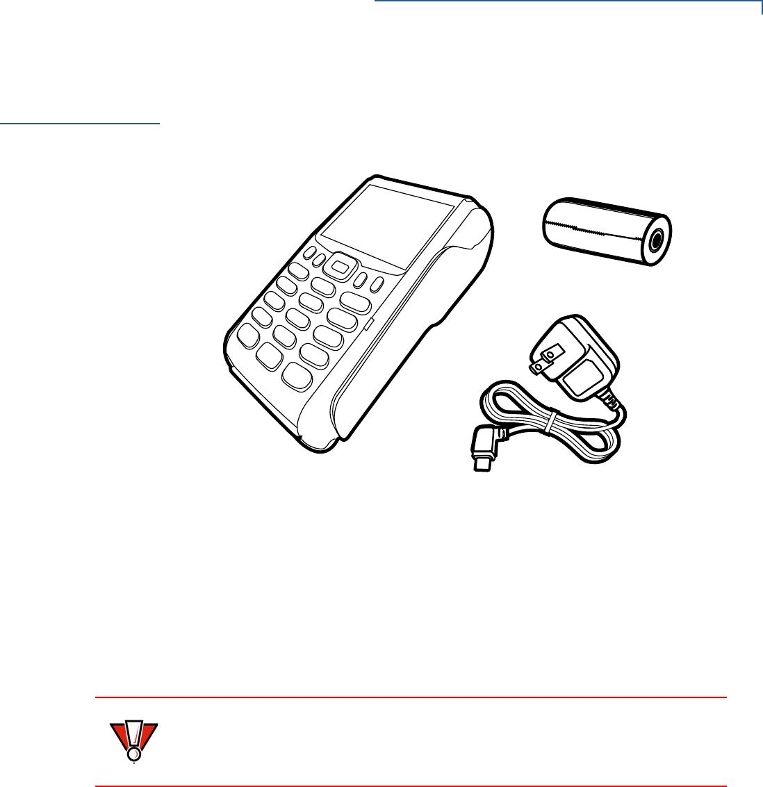
Open the shipping carton and carefully inspect its contents for possible tampering
or shipping damage. The device is a secure product and any tampering may
cause it to cease functioning properly.
Figure 2 VX 675 Shipping Carton Contents
To unpack the
Shipping Carton 1Remove and inspect the following items:
•Terminal
•Power pack
•Paper roll
2Remove all plastic wrapping from the terminal and other components.
3Remove the clear protective film from the LCD screen.
4Save the shipping carton and packing material for future repacking or moving
the terminal.
CAUTION
Do not use a terminal that has been damaged or tampered with. The
terminal comes equipped with tamper-evident labels. If a label or component
appears damaged, please notify the shipping company and your VeriFone
representative or service provider immediately.
TERMINAL SETUP
Examining Terminal Features
16 VX 675 INSTALLATION GUIDE
Examining
Terminal
Features
Before you continue the installation process, see the terminal features illustrated
below.
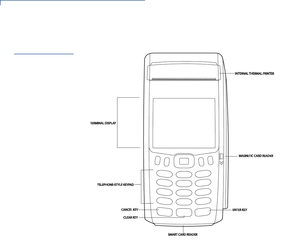
Figure 3 VX 675 Terminal Features (Front Panel)
Front Panel
The front panel includes the following features:
•A 2.8” TFT LCD display.
•The keypad consists of:
aA 12-key, telephone-style keypad (keypads may vary in style).
bThree color-coded keys below the keypad (from left to right: CANCEL,
CLEAR, ENTER).
cFour function keys below the display (PF1, PF2, PF3, PF4) and a five-
way navigational key in the middle.
•A magnetic card reader, built into the right side. Swipe the card using the
proper direction, with the magnetic stripe down and facing inward, toward the
keypad.
•An internal thermal printer at the top front of the terminal.
TERMINAL SETUP
Examining Connection Port
VX 675 INSTALLATION GUIDE 17
•A smart card reader, built into the bottom of the terminal. For directions on
how to use a smart card, see Conducting Smart Card Transactions.
•A SAM (security access module) compartment, built into the bottom of the
terminal inside the back compartment. The VX 675 terminal contains an
MSAM cardholder to support stored-value card programs or other merchant
card requirements.
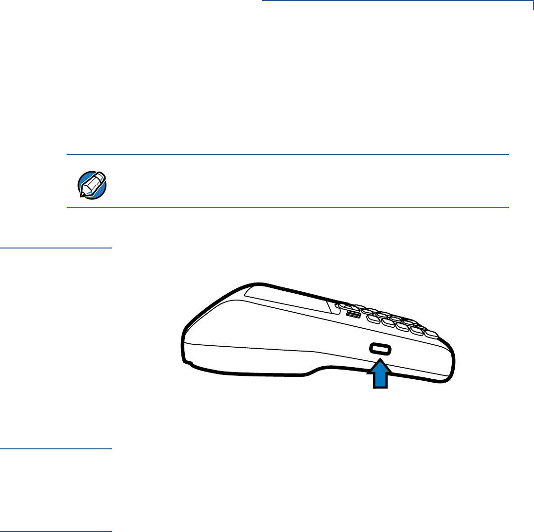
Examining
Connection Port
VX 675 has one primary micro-USB port used for power and download.
VX 675 3G and VX 675 WiFi-BT support USB Host function via primary micro-
USB port.
Figure 4 The VX 675 Primary Micro-USB Port
3G Support
VX 675 3G variant uses Cinterion PHS8-P radio module that incorporates 3G
High-Speed Packet Access (HSPA+) connectivity. To connect to existing 3G
operator-provided infrastructure, check that SIM has been inserted, see Installing
the SIM Card.
WiFi Bluetooth
Support
VX 675 WiFi-BT integrated module uses Broadcomm BCM4329 chip, which
provides SDIO interface for WiFi and UART interface for Bluetooth.
The module includes an integrated WLAN RF transceiver optimized for use in
Wireless LAN systems with advanced power management unit, and an integrated
radio transceiver optimized for use in Bluetooth wireless systems.
NOTE
VeriFone ships variants of the VX 675 terminal for different markets. Your terminal
may have a different configuration. However, the basic processes described in this
guide remain the same, regardless of terminal configuration.
TERMINAL SETUP
Installing the Paper Roll
18 VX 675 INSTALLATION GUIDE
Installing the
Paper Roll
A fast, quiet thermal printer is built into the VX 675 terminal. Before you can
process transactions that require a receipt or record, you must install a roll of
thermal-sensitive paper in the printer.
The ITP uses a roll of single-ply, thermal-sensitive paper—25 mm (for GPRS
model only) and 40 mm. A pink out-of-paper indicator line appears on the edge of
the paper approximately 18 inches before the end of the roll. After this line
appears, there is enough paper remaining on the roll to conclude at least one
transaction.
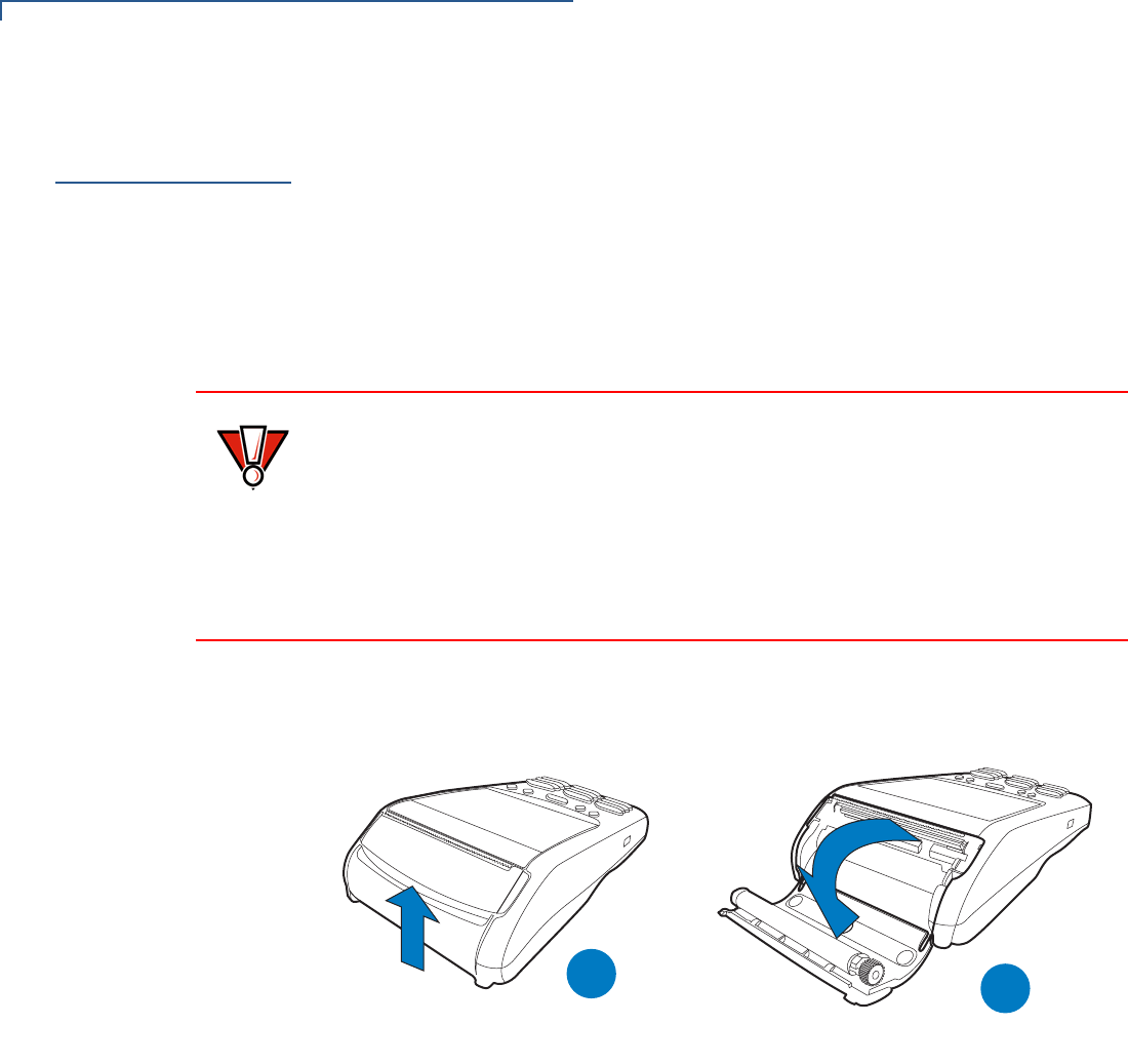
To Install a Paper Roll 1Gently pull the latch located on the bottom of the terminal to unlock the paper
roll cover.
Figure 5 Unlocking the Printer Cover
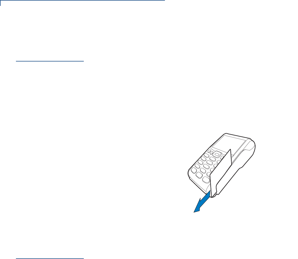
2Lift the printer cover up and back.
3Remove any partial roll of paper in the printer tray.
4Loosen the glued leading edge of the new roll of paper or remove the
protective strip, if applicable. Unwind the paper roll past any glue residue.
5Hold the roll so the paper feeds from the bottom of the roll when the terminal is
inverted (see illustration below).
CAUTION
Poor-quality paper can jam the printer and create excessive paper dust. To order
high-quality VeriFone paper, refer to Accessories and Documentation.
Store thermal paper in a dry, dark area. Handle thermal paper carefully: impact,
friction, temperature, humidity, and oils affect the color and storage
characteristics of the paper.
Never load a roll of paper with folds, wrinkles, tears, or holes at the edges in the
print area.
B
A
TERMINAL SETUP
Installing the Paper Roll
VX 675 INSTALLATION GUIDE 19
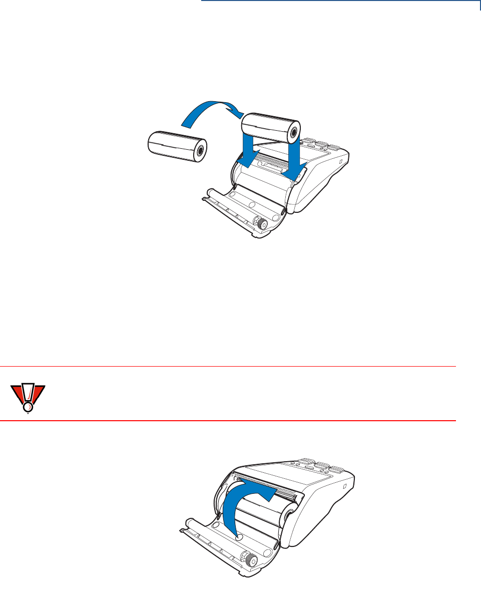
6Drop the paper roll into the printer tray.
Figure 6 Loading a 25mm Paper Roll
7Pull paper up past the glue residue on the paper roll.
8Close the paper roll cover by gently pressing directly on the cover until it clicks
shut, allowing a small amount of paper past the glue residue to extend outside
the printer door.
Figure 7 Closing Paper Roll Cover
9Tear the paper off against the serrated plastic strip in the printer.
CAUTION
To prevent damaging the print roller, always gently press down on the paper roll
cover to close it.
TERMINAL SETUP
Installing the SIM Card
20 VX 675 INSTALLATION GUIDE
Installing the
SIM Card
VX 675 supports GSM SIM (Subscriber Identity Module).
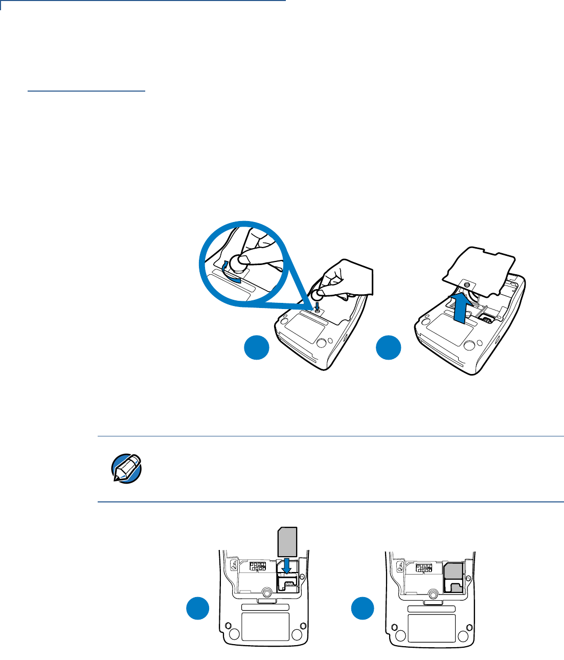
To install or replace
the card 1Turn off the terminal.
2Place the terminal upside down on a soft, clean surface to protect the lens
from scratches.
3Unscrew and remove the back compartment cover.
4Lift the battery pack.
Figure 8 Removing the Back Compartment Cover
5Insert the SIM card into the cardholder as shown below.
Figure 9 Inserting the SIM Card
6Return the battery pack to its original position.
7Close and screw the back compartment cover.
B
A
NOTE
Ensure that the card’s gold contacts are facing the compartment. The cardholder
connector base has a set of contacts and a notch to ensure the SIM card is
positioned correctly. The SIM card has a notch on one corner to ensure that it fits
into the connector base in only one way.
DC
MI
S
M
IS
AB
TERMINAL SETUP
Installing and Replacing SD Card
VX 675 INSTALLATION GUIDE 21
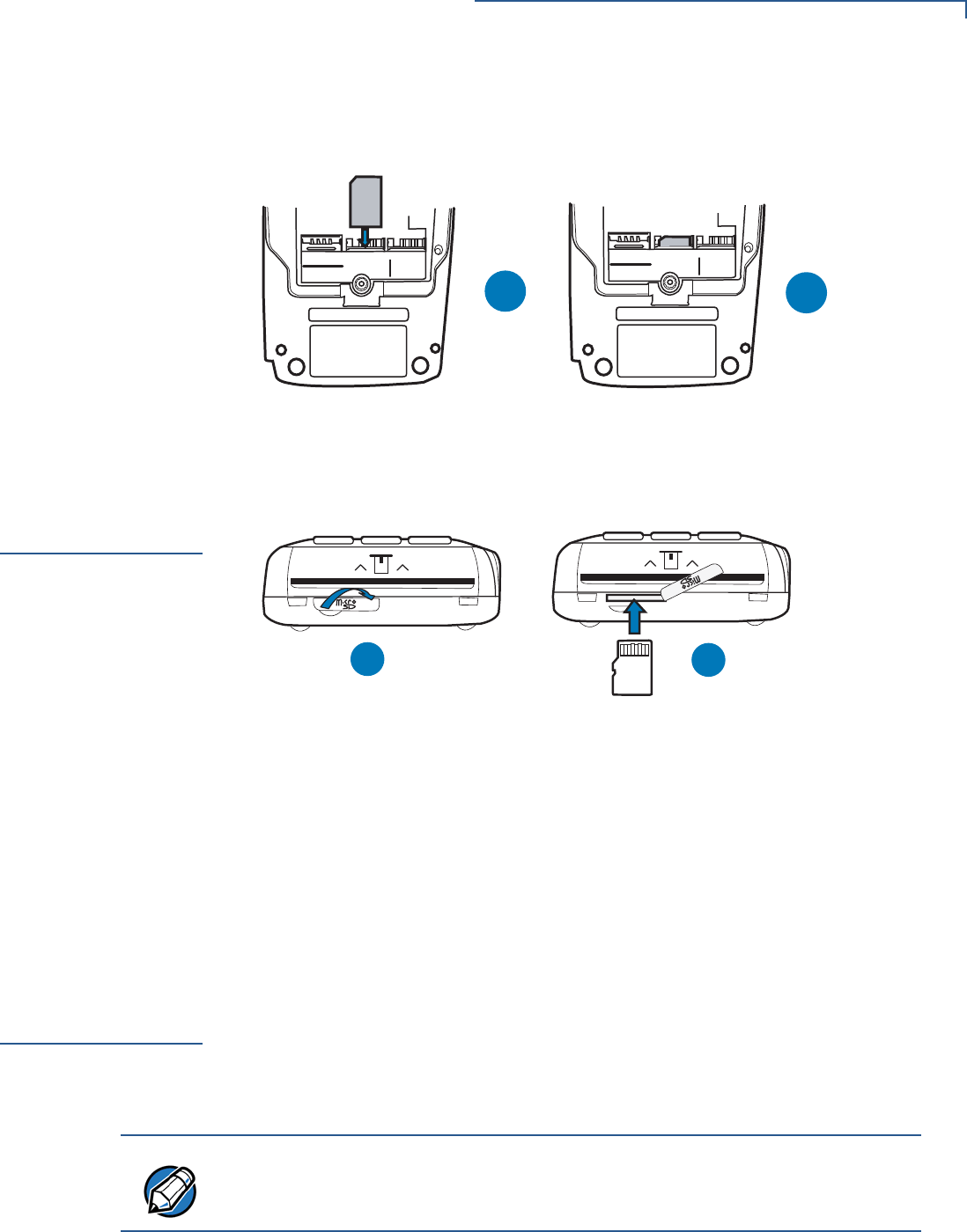
Dual SIM
VX 675 3G supports dual SIM and SIM detect behavior for SIM 2. SIM 1 is the
primary default SIM and SIM 2 acts as backup SIM.
Figure 10 VX 675 3G SIM Installation
Installing and
Replacing SD
Card
Vx675 3G and WiFi-BT support an optional SD flash memory.
Figure 11 SD Card Installation/Replacement on VX 675 3G/VX 675 WiFi-
BT
To install or replace
SD card 1Turn off the terminal.
2Gently pull the rubber covering of the SD card slot located near the smart card
reader and slide sideways to expose the card slot.
3Insert the card into the slot.
4Return the cover of the card slot.
Using the
Battery
The VX 675 terminal uses a single cell Li-ion battery (see Accessories and
Documentation for ordering information). The internal logic of the battery prevents
both overcharging and undercharging (a fault condition in which the battery level
goes well below the minimum acceptable charge and the battery becomes
unusable).
C
A
SAM1 - LOWER
SAM2 - UPPER
SIM 1 SIM 2
D
B
SAM1 - LOWER
SAM2 - UPPER
SIM 1 SIM 2
AB
B
NOTE
The VX 675 terminal will only operate when the battery is installed.

TERMINAL SETUP
Battery Behavior (No Power Pack)
22 VX 675 INSTALLATION GUIDE
Battery Features
The following are features of the battery:
•Single Li-ion cell.
•A safety circuit that:
•Prevents cell damage from overcharge, over-discharge, or overheating.
•Activates when the battery is left in an unused terminal for extended
periods.
Conserve battery power by turning the VX 675 terminal off when not in use. Keep
the Li-ion battery inserted in the terminal and power up the terminal periodically to
check the battery charge. Do not let the battery charge fall below 10% for
extended periods of time as this may permanently diminish the battery capacity.
Recharge the battery by attaching the micro-USB end of the power pack to the
terminal and plugging the other end of the power pack into a wall outlet.
Battery Behavior
(No Power Pack)
The terminal shifts to power pack mode and starts up automatically when the
VX 675 is connected to a non-battery power source, regardless of the battery
charge state.
Manual Startup
Hold the green key down for about 4 seconds until the terminal displays the
startup screen.
The terminal lights up once the power is on.
NOTE
VX 675 battery pack is not customer changeable and therefore should not be
disconnected and removed.
Li-ion batteries are not affected by shallow charging. When the terminal has no
external power source or battery, the coin cell battery provides power to the
security circuit.
Disconnecting and removing the battery, as well as unplugging the terminal
power pack, reduce the life of the coin cell battery, which does not recharge and
must be replaced if drained.
NOTE
The 4-second power-up delay prevents terminal startup if the green key is
accidentally held down. The time required to hold the green key down to power up
the terminal is configurable (for more information, see the VX 675 Reference
Guide – VPN DOC265-004-EN-A).
NOTE
The VeriFone copyright screen starts and displays a unique copyright screen
once the terminal loads an application. However, DOWNLOAD NEEDED appears on
screen after the initial VeriFone copyright screen if there is no available
application in the terminal.

TERMINAL SETUP
Connecting the Terminal Power Pack
VX 675 INSTALLATION GUIDE 23
Manual Shutdown
Hold the red key down for about 4 seconds until the terminal displays the
shutdown verification screen. Keep holding the red key until the VX 675 terminal
shuts down.
Connecting the
Terminal Power
Pack
After installing the battery, connect the VX 675 terminal to the provided power
source for initial charging.
Each VX 675 terminal comes with power supply (VPN PWR265-001-01-A) used
to connect the terminal directly to a power outlet and to charge the battery. The
VX 675 unit comes with a universal input power pack capable of operating from
voltages of 100 V to 240 V AC.
NOTE
•The 4-second shutdown delay that prevents terminal shutdown if the red key
is accidentally held down. The time required to hold the red key down to shut
down the terminal is configurable (for more information, see the VX 675
Reference Guide – VPN DOC265-004-EN-A).
•The screen is blank when the terminal has no power.
CAUTION
Using an incorrectly rated power supply may damage the terminal or cause it not
to work as specified. Before troubleshooting, ensure that the power supply being
used to power the terminal matches the requirements specified on the bottom of
the terminal. (See Specifications for detailed power supply specifications.) Obtain
the appropriately rated power supply before continuing with troubleshooting.
WARNING
Do not plug the power pack into an outdoor outlet or operate the terminal
outdoors.
During a transaction, disconnecting the power by removing the battery or
unplugging the terminal from a wall power while at very low battery charge may
cause transaction data files not yet stored in the terminal memory to be lost.
TERMINAL SETUP
Charging the Battery
24 VX 675 INSTALLATION GUIDE
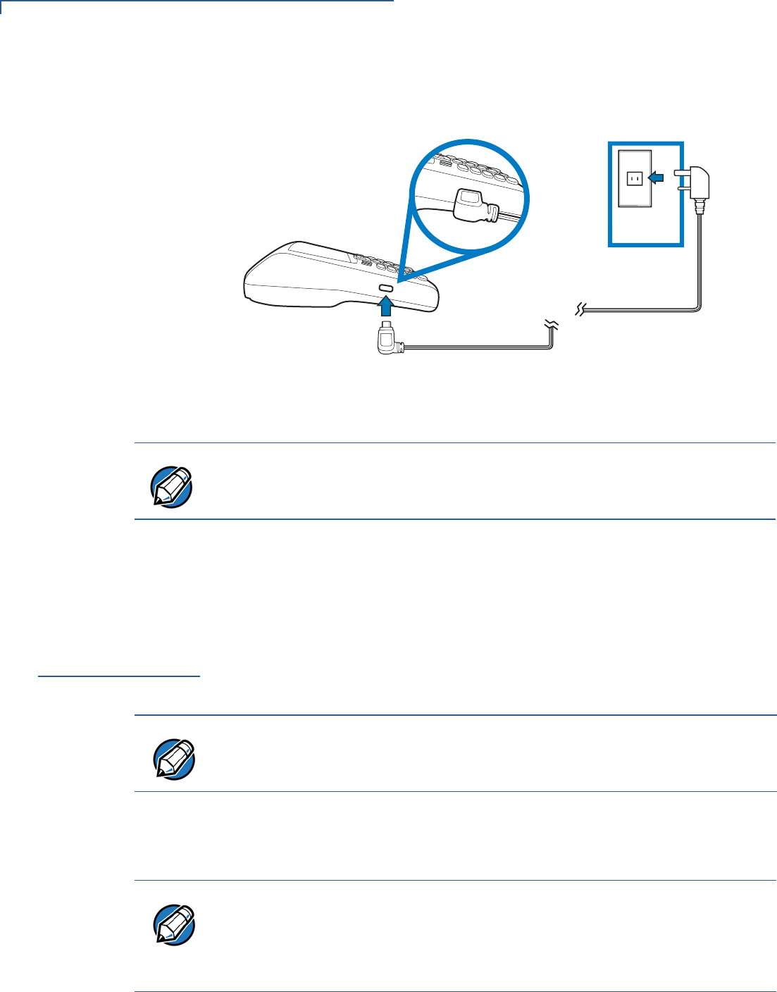
To Connect the
Terminal Power
Supply
1Insert the micro-USB plug into the micro-USB port of the VX 675, as shown in
the figure below.
Figure 12 VX 675 Power Supply Connection
2Plug the AC power pack into a wall outlet or powered surge protector.
Once it loads the application, the terminal starts the initial VeriFone copyright
screen and displays a unique copyright screen. If there is no available application
in the terminal, DOWNLOAD NEEDED appears on screen after the initial VeriFone
copyright screen.
Charging the
Battery
After unpacking your VX 675 terminal, connect the power pack to the unit for 6
hours or until fully charged.
The battery has a safety circuit to protect the Li-ion cells from overcharging and
over-discharging. If the battery is over-discharged, the safety circuit shuts down
the battery. The battery must then be recharged to restore operation.
NOTE
To protect against possible damage caused by lightning strikes and electrical
surges, consider installing a power surge protector.
NOTE
The terminal charges the VX 675 battery when the terminal is on the base. For
more information, see Docking the Terminal on the Base.
NOTE
The VX 675 terminal automatically shuts off when the battery reaches the
critically low charge state. If this occurs, the battery must be recharged for a
minimum of 1/2 hour before it can power the terminal. It may take several
recharge attempts to reset the safety circuit when charging a battery that has
been discharged below this critical state.
TERMINAL SETUP
VX 675 Base Stations
VX 675 INSTALLATION GUIDE 25
Battery Life
Charging and discharging the VX 675 battery hundreds of times will wear out the
battery. Significantly reduced operating times indicate the need for battery
replacement (see Accessories and Documentation for ordering information).
VX 675 Base
Stations
Like the terminal, VeriFone ships variants of the VX 675 base for different
markets. Your base may have a different configuration.
USB Base
A charging base to charge the terminal and provide a docking station when the
terminal is not in use. It also has USB Host port for downloading applications and
secure keys via USB flash drive. The base can be positioned on a countertop.
Figure 13 USB Base Showing Micro-USB and USB Host Ports
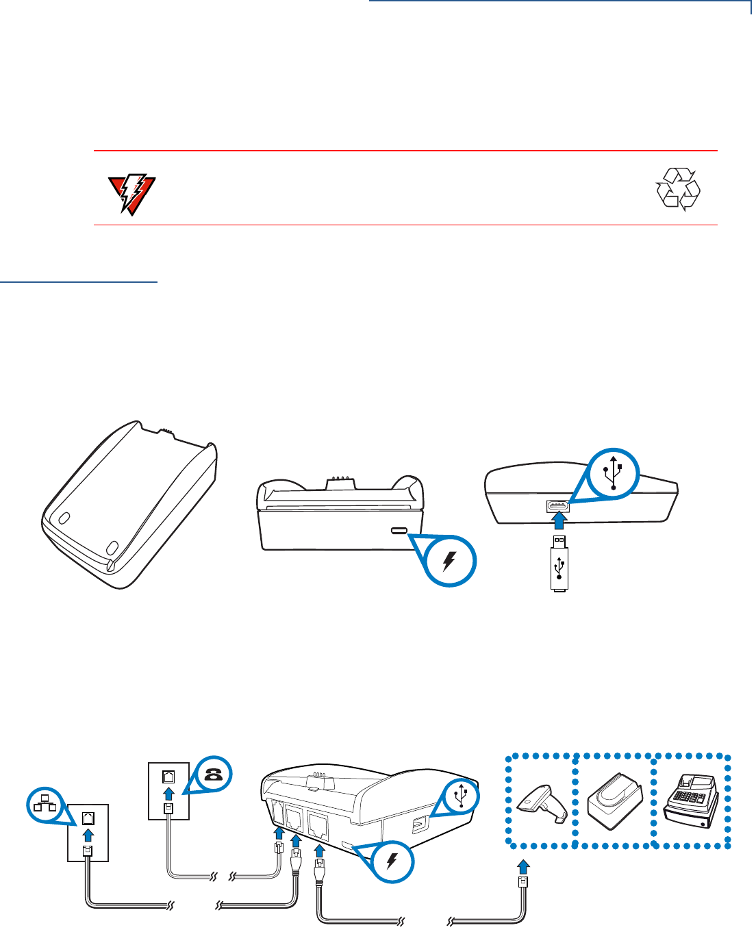
Full-Feature Base
A charging base with Dial, Ethernet, Serial, and USB host for full back-up
connectivity options and support to some peripherals like ECR, check reader, and
barcode reader, among others.
Figure 14 Full-Feature Base Showing Dial, Ethernet, Serial, Micro-USB
and USB Host Ports
WARNING
Do not dispose of batteries in a fire. Li-ion batteries must be recycled
or disposed of properly. Do not dispose of Li-ion batteries in municipal
waste sites.
TERMINAL SETUP
Powering Up the Base
26 VX 675 INSTALLATION GUIDE
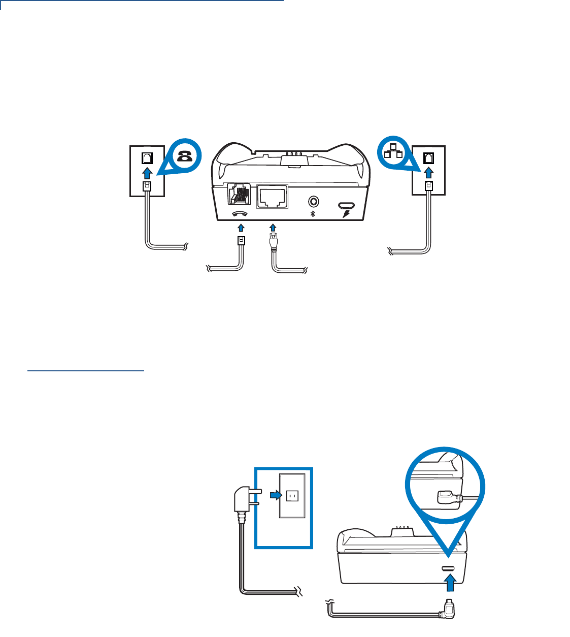
Bluetooth Base
A base station that relays wireless data received from the terminal via modem and
transmits back the response to the terminal. It also supports Dial and Ethernet
connectivity options.
Figure 15 Bluetooth Base
Powering Up the
Base
Use the procedure below to connect VX 675 Base to a power source.
To power up the base 1Insert the micro-USB plug into the micro-USB port of the base, as shown in
the figure below.
Figure 16 Connecting the Base to a Power Source
2Plug the AC power pack into a wall outlet or power surge protector.
ETH
TERMINAL SETUP
Docking the Terminal on the Base
VX 675 INSTALLATION GUIDE 27
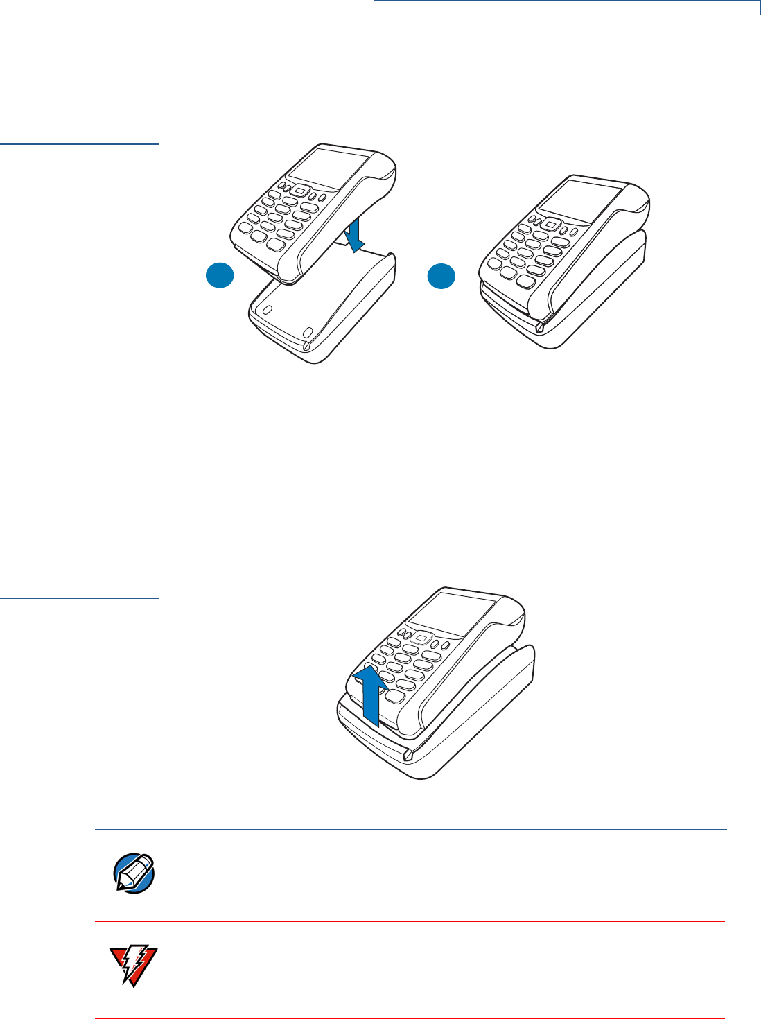
Docking the
Terminal on the
Base
The VX 675 terminal can be placed on the base when not in use for continuous
charging of its battery.
Figure 17 Docking the VX 675 Terminal on the Base
To place the terminal
on the base 1Place the top portion of the terminal on the base. Ensure that the recess on
the bottom of the terminal sits on top of the pogo pins.
2Push the terminal to dock. You will hear a snap indicating that the terminal is
securely hooked to the base.
Undocking the
Terminal from
the Base
The VX 675 terminal can be taken from the base when in use.
Figure 18 Undocking the VX 675 Terminal from the Base
AB
NOTE
To protect against possible damage caused by lightning strikes and electrical
surges, consider installing a power surge protector.
WARNING
Do not plug the power pack into an outdoor outlet or operate the terminal
outdoors.
Disconnecting the power during a transaction may cause transaction data files
not yet stored in terminal memory to be lost.
TERMINAL SETUP
Connecting to USB Host
28 VX 675 INSTALLATION GUIDE
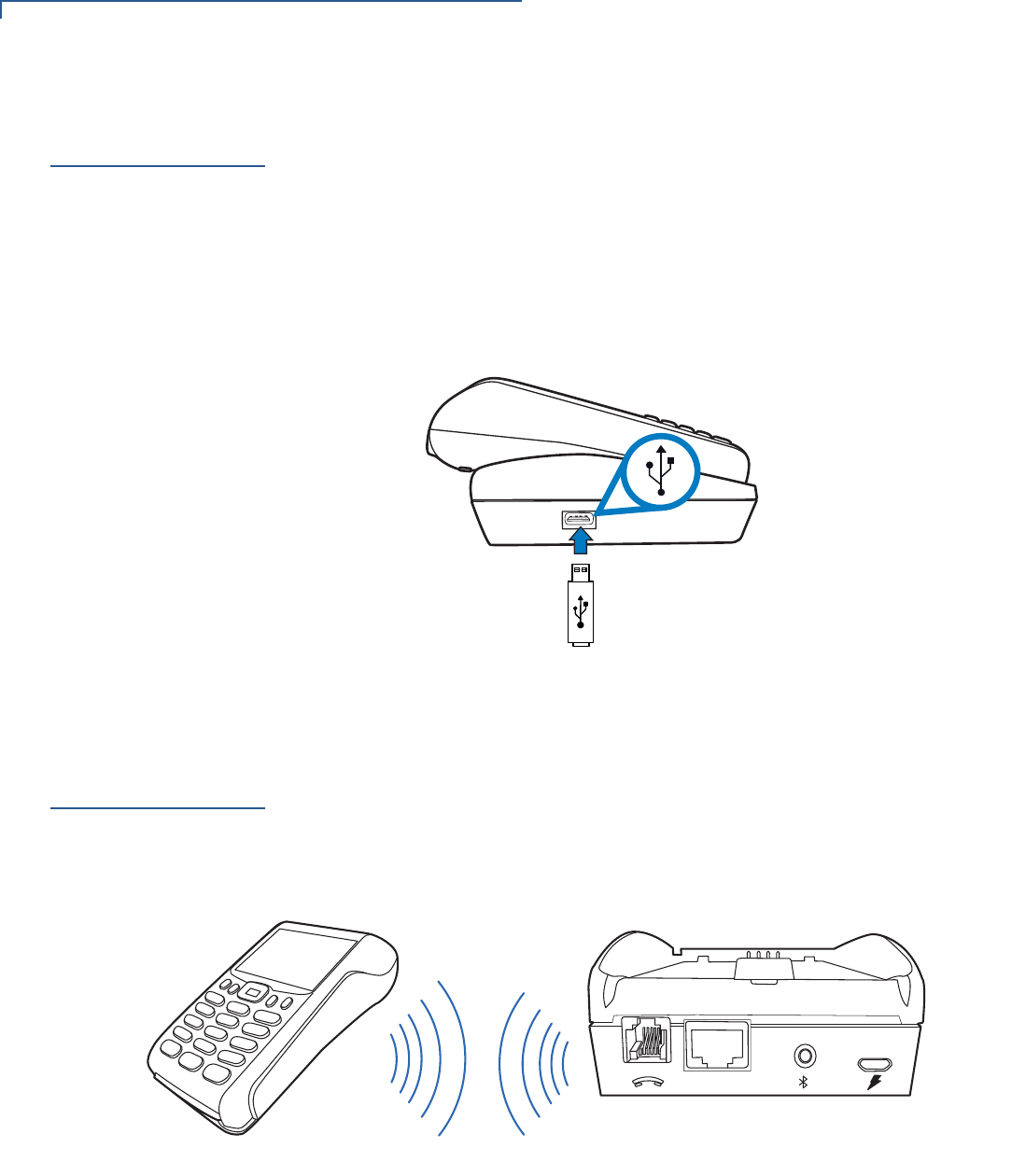
Connecting to
USB Host
USB Host lets you download applications and secure keys via USB flash drive.
To connect to the
USB Host 1Power up the base. Insert the micro-USB plug into the micro-USB port of the
base and plug the AC power pack into a wall outlet or power surge protector.
2Make sure that the terminal is docked on the base.
3Insert the USB flash drive into the USB port on the left side of the base.
Figure 19 Connecting USB Flash Drive to the USB Host
Conducting a
Bluetooth
Transaction
VX 675 BT Base relays wireless data received from the terminal via modem and
then transmits back the response to the terminal. It pairs with the Bluetooth Base
to go online for authorization. These are both Class 1 Bluetooth devices providing
secure radio communication.
Figure 20 VX 675 WiFi-BT Terminal Communicating with the Bluetooth
Base
To improve the range performance of the terminal, place the Bluetooth Base in a
location that services all of the card payment areas in the premises. Ideally, place
it within line of sight of all areas of card acceptance.
ETH
TERMINAL SETUP
Conducting Wireless Transactions
VX 675 INSTALLATION GUIDE 29
To Conduct a
Bluetooth
Transaction:
•Ensure that the terminal is paired with the Bluetooth Base not more than 100
meters away.
•Follow the on-screen instructions provided with your application.
Conducting
Wireless
Transactions
To conduct a wireless transaction:
•Ensure the terminal is in an optimal position for transmitting.
•Follow the on-screen instructions provided with your application.
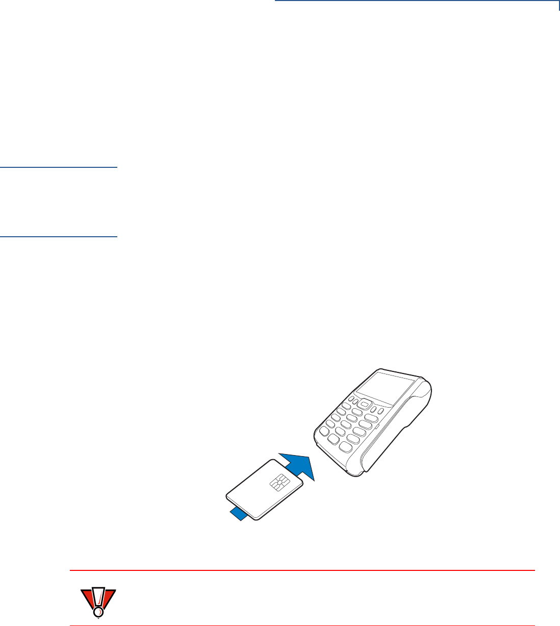
Conducting
Smart Card
Transactions
The smart card transaction procedure may vary from one application to another.
Verify the procedure with your application provider before performing a smart card
transaction.
To Conduct a Smart
Card Transaction 1Position a smart card with the contacts facing upward (see illustration below).
2Insert the smart card into the smart card reader slot in a smooth, continuous
motion until it seats firmly.
3Remove the card only when the application indicates the transaction is
complete.
Figure 21 Inserting a Smart Card
CAUTION
Do not remove the smart card in the card reader until the transaction is complete.
Premature card removal will invalidate the transaction.
TERMINAL SETUP
Using the Magnetic Card Reader
30 VX 675 INSTALLATION GUIDE
Using the
Magnetic Card
Reader
The VX 675 terminal supports credit/debit card transactions.
To Conduct a Credit
or Debit Card
Transaction
1Position a magnetic card with the stripe in the card reader and facing inward,
toward the keypad.
2To ensure a proper read of the magnetic swipe card, the user should insert the
magnetic card from the top of the unit, as shown in the following illustration.
3Swipe the card through the magnetic card reader.
Figure 22 Using the Magnetic Card Reader
ECR (Fiscal
Module) Support
The fiscal module allows the ECR to have direct connection to the Ministry of
Finance servers. When a mobile transaction is made, the transaction data is sent
to the Ministry of Finance servers, and then to the banking host system.
The fiscal module stores transaction data of up to 2MB. It is secured by a metallic
seal placed on the right side of the terminal, under the MSR.
TERMINAL SETUP
ECR (Fiscal Module) Support
VX 675 INSTALLATION GUIDE 31
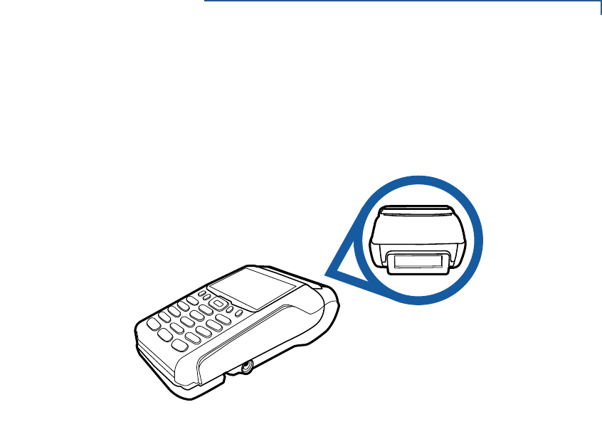
Customer Display
There is a 42mm single-line, customer-facing display at the bottom of the paper
roll cover. This displays up to eight characters including “,” or “.” between any
character.
Figure 23 VX 675 Customer Display

TERMINAL SETUP
ECR (Fiscal Module) Support
32 VX 675 INSTALLATION GUIDE

VX 675 INSTALLATION GUIDE 33
CHAPTER 3
Specifications
This chapter discusses power requirements, dimensions, and other specifications
of the VX 675 terminal.
Power
5V DC 1.0 A
DC Power Pack
UL, ITE listed, LPS power supply:
aInput rated: 100-240V AC, 50/60 Hz
bOutput rated: 5V DC 1.0 A
Temperature
•Operating temperature: 0C to 50C (32F to 122F)
•Non-operating temperature: -30C to 60C (-22F to 140F)
•Relative humidity: 5% to 90%; non-condensing
External
Dimensions
•Length: 148 mm (5.8 in)
•Width: 78 mm (3.1 in)
•Depth: 42 mm (1.6 in)

SPECIFICATIONS
External Dimensions
34 VX 675 INSTALLATION GUIDE
VX 675 INSTALLATION GUIDE 35
CHAPTER 4
Maintenance
The VX 675 terminal and base have no user-serviceable parts.
Cleaning the
Terminal
To clean the terminal and base, use a clean cloth slightly dampened with water
and a drop or two of mild soap. For stubborn stains, use alcohol or an alcohol-
based cleaner.
Terminal
Contacts
Gently swab the contacts with alcohol or contact cleaner to remove the dirt. It is
important that the exposed contacts of the VX 675 battery stay clean and unbent.
Smart Card
Reader
Do not attempt to clean the smart card reader. Doing so may void any warranty.
For smart card reader service, contact your VeriFone distributor or service
provider.
CAUTION
Never use thinner, trichloroethylene, or ketone-based solvents – they may cause
deterioration of plastic or rubber parts.
Do not spray cleaners or other solutions directly onto the keypad or terminal
display.
CAUTION
Avoid touching the contacts of the VX 675 battery and the recessed area on the
terminal. Finger oils tarnish contacts, causing bad connections. When operating
on battery power and experiencing a high occurrence of bad or incomplete data
transfers, clean the contacts.

MAINTENANCE
Smart Card Reader
36 VX 675 INSTALLATION GUIDE

VX 675 INSTALLATION GUIDE 37
CHAPTER 5
VeriFone Service and Support
For VX 675 terminal problems, contact your local VeriFone representative or
service provider.
For VX 675 product service and repair information:
•USA – VeriFone Service and Support Group, 1-800-VeriFone (837-4366),
Monday - Friday, 8 A.M. - 8 P.M., Eastern time
•International – Contact your VeriFone representative
Returning a
Terminal for
Service
Before returning a VX 675 terminal or base to VeriFone, you must obtain an MRA
number. The following procedure describes how to return one or more VX 675
terminals or bases for repair or replacement (U.S. customers only).
To Return a Terminal
for Service 1Get the following information from the printed labels on the bottom of each
VX 675 terminal or base to be returned:
•Product ID, including the model and part number. For example, “VX 675”
and “M265-XXX-XX-XXX-2.”
•Serial number (S/N nnn-nnn-nnn)
2Obtain the MRA number(s) by completing one of the following:
aCall VeriFone toll-free within the United States at 1-800-VeriFone and
follow the automated menu options.
•Select the MRA option from the automated message. The MRA
department is open Monday to Friday, 8 A.M.–8 P.M., Eastern Time.
•Give the MRA representative the information you gathered in Step 1.
If the list of serial numbers is long, you can fax the list, along with the
information gathered in Step 1, to the MRA department at 727-953-
4172 (U.S.).
bAddress a fax to “VeriFone MRA Dept.” with the model and part number(s)
•Include a telephone number where you can be reached and your fax
number.
NOTE
Customers outside the United States are advised to contact their local VeriFone
representative for assistance regarding service, return, or replacement of
terminals or batteries.
VERIFONE SERVICE AND SUPPORT
Accessories and Documentation
38 VX 675 INSTALLATION GUIDE
cComplete the Inquiry Contact Form at http://www.verifone.com/aboutus/
contact/contact_form.cfm.
•Address the Subject box with to “VeriFone MRA Dept.”
•Reference the model and part number in the Note box.
3Describe the problem(s).
4Provide the shipping address where the repaired or replacement unit must be
returned.
5Keep a record of the following items:
•Assigned MRA number(s).
•VeriFone serial number assigned to the VX 675 terminal or base you are
returning for service or repair (terminal serial numbers are located on the
bottom of the unit.
•Shipping documentation, such as air bill numbers used to trace the
shipment.
•Model(s) returned (model numbers are located on the VeriFone label on
the bottom of the VX 675 terminal).
Accessories and
Documentation
VeriFone produces the following accessories and documentation for the
VX 675 terminal. When ordering, please refer to the part number in the left
column.
•VeriFone online store at www.store.verifone.com
•USA – VeriFone Customer Development Center, 800-VeriFone (837-4366),
Monday - Friday, 7 A.M. - 8 P.M., Eastern time
•International – Contact your VeriFone representative
Power Pack
Contact your local VeriFone distributor to determine which power pack fits
your needs.
Printer Paper
VeriFone Cleaning
Kit
NOTE
One MRA number must be issued for each VX 675 terminal you return to
VeriFone, even if you are returning several of the same model.
VPN PWR265-001-01-A DC Power Pack (Universal)
VPN PPR265-001-01-A 25 mm (0.98 in) diameter, 57 mm (2.24 in) wide
VPN PPR268-001-01-A 40 mm (1.57 in) diameter, 57 mm (2.24 in) wide
VPN 02746-01 Cleaning Kit

VERIFONE SERVICE AND SUPPORT
Accessories and Documentation
VX 675 INSTALLATION GUIDE 39
Micro-USB Cable
Documentation
VPN SUB265-001-01-A Micro-USB service dongle
VX 675 Certifications and Regulations Sheet VPN DOC265-001-EN
VX 675 Quick Installation Guide VPN DOC265-002-EN
VX 675 Reference Guide VPN DOC265-004-EN
Verix eVo Volume I: Operating System Programming
Manual
VPN DOC00301
Verix eVo Volume II: Operating System and
Communications Programmers Manual
VPN DOC00302
VX 675 USB Only Base Quick Installation Guide DOC265-025-EN
VX 675 Full-Feature Base Quick Installation DOC265-026-EN
VX 675 ECR Quick Installation Guide DOC265-028-EN

VERIFONE SERVICE AND SUPPORT
Accessories and Documentation
40 VX 675 INSTALLATION GUIDE
VX 675 INSTALLATION GUIDE 41
CHAPTER 6
Troubleshooting
Guidelines
The troubleshooting guidelines provided in the following section are included to
help you install and configure your VX 675 terminal successfully. Typical
examples of malfunction you may encounter while operating your VX 675 terminal
and steps you can take to resolve them are listed in this chapter.
If the problem persists even after performing the outlined guidelines or if the
problem is not described below, contact your local VeriFone representative for
assistance.
Terminal Does
Not Start
•Ensure that the battery charge state is not below the critically low level.
•Recharge or replace the battery.
•Ensure that you pressed the green ENTER/ON key for approximately 4
seconds, until the unit lights up.
Terminal Display
Does Not Show
Correct/
Readable Info
•Recharge or replace the battery.
•Connect the VX 675 terminal into a known-good power supply (if you have
one) to see if this clears the problem.
•If the problem persists, contact your local VeriFone representative for
assistance.
NOTE
The VX 675 terminal comes equipped with tamper-evident labels. The VX 675 unit
contains no user serviceable parts. Do not, under any circumstance, attempt to
disassemble the terminal. Perform only those adjustments or repairs specified in
this guide. For all other services, contact your local VeriFone service provider.
Service conducted by parties other than authorized VeriFone representatives may
void any warranty.
CAUTION
Use only a VeriFone-supplied power pack. Using an incorrectly rated power
supply may damage the terminal or cause it not to work as specified. Before
troubleshooting, ensure that the power supply being used to power the terminal
matches the requirements specified on the bottom of the terminal. (See
Specifications, for detailed power supply specifications.) Obtain the appropriately
rated power supply before continuing with troubleshooting.

TROUBLESHOOTING GUIDELINES
Battery Does Not Charge
42 VX 675 INSTALLATION GUIDE
Battery Does Not
Charge
The VX 675 battery must initially receive a full charge to ensure proper operation.
Blank Display
When the VX 675 terminal display screen does not show correct or clearly
readable information:
•The battery pack may not be connected properly. Remove and reinstall the
battery pack.
•Check terminal power connection.
•Remove and reapply power to the terminal.
•If the problem persists, contact your local VeriFone service provider.
Printer Does Not
Print
If the printer does not work properly:
•Make sure the battery is properly installed in the terminal. The printer will not
print if there is no battery in the terminal.
•Check battery status or terminal power connection. The printer will not print if
there is an insufficient charge remaining in the battery to complete the print
operation.
•Check if the printer is out of paper (slow red blinking light) and that the roll is
properly installed. Open the paper roll cover and install a new roll of printer
paper or ensure that the roll is feeding correctly. A solid red indicator light
indicates a printer error.
NOTE
•Allow the VX 675 terminal to remain connected to the power pack for 6 hours
to ensure the battery receives a full charge.
•Li-ion batteries are not affected by shallow charging. Furthermore, when the
terminal has no external power source or battery the coin cell battery provides
power to the security circuit.
•Uninstalling the battery and unplugging the terminal power pack reduce the
life of the coin cell battery, which does not recharge and must be replaced if
drained.
•Conserve battery power by turning the VX 675 terminal off when not in use.
Keep the Li-ion battery inserted in the terminal and power up the terminal
periodically to check the battery charge. Do not let the battery charge fall
below 10% for extended periods of time as this may permanently diminish the
battery capacity. Recharge the battery by attaching USB end of the power
pack to the terminal and plugging the other end of the power pack into a wall
outlet.
•The VX 675 terminal automatically shuts off when the battery reaches the
critically low charge state. If this occurs, the battery must recharge a minimum
of 1/2 hour before it can power the terminal. It may take several recharge
attempts to reset the safety circuit when charging a battery that has been
discharged below this critical state.

TROUBLESHOOTING GUIDELINES
Printer Paper Jam
VX 675 INSTALLATION GUIDE 43
•Verify that the printer door is properly latched.
•If the problem persists, contact your VeriFone distributor or service provider.
Printer Paper
Jam
If paper jams inside the printer:
•Press the button at the bottom of the terminal to unlatch the paper roll cover,
then open the cover.
•Remove the damaged paper from the paper roll and clear the feed
mechanism.
•Install a roll of printer paper, as described in Installing the Paper Roll.
•If the problem persists, it may be due to poor paper quality. Install a new roll of
higher-quality paper.
Keypad Does
Not Respond
If the keypad does not respond properly:
•Check the terminal display. If it displays the wrong character or nothing at all
when you press a key, follow the steps outlined in Transactions Fail to
Process.
•If pressing a function key does not perform the expected action, refer to the
user documentation for that application to ensure you are entering data
correctly.
•If the problem persists, contact your local VeriFone representative.
Transactions
Fail to Process
There are several reasons why the terminal may not be processing transactions.
Use the following steps to troubleshoot failures.
Check the Magnetic Card Reader
•Perform a test transaction using one or more different magnetic stripe cards to
ensure the problem is not a defective card.
•Ensure that you are swiping cards properly. With the VX 675 card reader, the
black magnetic stripe on the card should face down and inward, toward the
keypad and must be inserted from the top of the terminal (see Figure 22).
•Process a transaction manually, using the keypad instead of the card reader. If
the manual transaction works, the problem may be a defective card reader.
•Contact your VeriFone distributor or service provider.
•If the manual transaction does not work, proceed to Check the Signal
Strength.
WARNING
Poor-quality paper may jam the printer. To order high-quality VeriFone paper,
refer to Accessories and Documentation.

TROUBLESHOOTING GUIDELINES
Transactions Fail to Process
44 VX 675 INSTALLATION GUIDE
Check the Smart Card Reader
•Perform a test transaction using several different smart cards to ensure the
problem is not a defective card.
•Ensure that the card is inserted correctly and that the card is not removed
prematurely.
•Contact your VeriFone distributor or service provider.
•If the manual transaction does not work, proceed to Check the Signal
Strength.
Check the Signal Strength
•On-screen signal-strength indicator displays at least one bar to indicate
connectivity to radio network.
•Ensure that the radio has been activated by your service provider.
.
Federal Communication Commission Interference Statement
This device complies with Part 15 of the FCC Rules. Operation is
subject to the following two conditions: (1) This device may not cause
harmful interference, and (2) this device must accept any interference
received, including interference that may cause undesired operation.
This equipment has been tested and found to comply with the limits for
a Class B digital device, pursuant to Part 15 of the FCC Rules. These
limits are designed to provide reasonable protection against harmful
interference in a residential installation. This equipment generates, uses
and can radiate radio frequency energy and, if not installed and used in
accordance with the instructions, may cause harmful interference to
radio communications. However, there is no guarantee that
interference will not occur in a particular installation. If this equipment
does cause harmful interference to radio or television reception, which
can be determined by turning the equipment off and on, the user is
encouraged to try to correct the interference by one of the following
measures:
Reorient or relocate the receiving antenna.
Increase the separation between the equipment and receiver.
Connect the equipment into an outlet on a circuit different from that
to which the receiver is connected.
Consult the dealer or an experienced radio/TV technician for help.
FCC Caution: Any changes or modifications not expressly approved by
the party responsible for compliance could void the user's authority to
operate this equipment.
This transmitter must not be co-located or operating in conjunction with
any other antenna or transmitter.
Radiation Exposure Statement:
This device meets the government’s requirements for exposure to radio
waves.
This device is designed and manufactured not to exceed the emission
limits for exposure to radio frequency (RF) energy set by the Federal
Communications Commission of the U.S. Government.
The exposure standard for wireless device employs a unit of
measurement known as the Specific Absorption Rate, or SAR. The SAR
limit set by the FCC is 1.6W/kg. *Tests for SAR are conducted using
standard operating positions accepted by the FCC with the device
transmitting at its highest certified power level in all tested frequency
bands.
Industry Canada statement
This device complies with Industry Canada license-exempt RSS standard(s). Operation is
subject to the following two conditions:
(1) this device may not cause interference, and
(2) this device must accept any interference, including interference that may cause undesired
operation of the device.
Le présent appareil est conforme aux CNR d'Industrie Canada applicables aux appareils radio
exempts de licence. L'exploitation est autorisée aux deux conditions suivantes:
(1) l'appareil ne doit pas produire de brouillage, et
(2) l'utilisateur de l'appareil doit accepter tout brouillage radioélectrique subi, même si le
brouillage est susceptible d'en compromettre le fonctionnement."
This Class B digital apparatus complies with Canadian ICES-003.
Cet appareil numérique de la classe B est conforme à la norme NMB-003 du Canada.
Radiation Exposure Statement:
The product comply with the Canada portable RF exposure limit set forth for an uncontrolled
environment and are safe for intended operation as described in this manual. The further RF
exposure reduction can be achieved if the product can be kept as far as possible from the user
body or set the device to lower output power if such function is available.
Déclaration d'exposition aux radiations:
Le produit est conforme aux limites d'exposition pour les appareils portables RF pour les Etats-Unis
et le Canada établies pour un environnement non contrôlé.
Le produit est sûr pour un fonctionnement tel que décrit dans ce manuel. La réduction aux
expositions RF peut être augmentée si l'appareil peut être conservé aussi loin que possible du
corps de l'utilisateur ou que le dispositif est réglé sur la puissance de sortie la plus faible si une telle
fonction est disponible.
This device and its antenna(s) must not be co-located or operating in conjunction with any
other antenna or transmitter, except tested built-in radios.
Cet appareil et son antenne ne doivent pas être situés ou fonctionner en conjonction avec une
autre antenne ou un autre émetteur, exception faites des radios intégrées qui ont été testées.