Vertex Standard USA 11143040 VHF MOBILE TRANSCEIVER User Manual
Vertex Standard USA, Inc. VHF MOBILE TRANSCEIVER Users Manual
Users Manual
EVX-5300
Operating Manual
prOgraMMable FunctiOns/Features
6ProgrammableFunctionKeys
2-ToneEncode/Decodeø
5-ToneEncode/Decodeø
MDC-1200®Encode/Decodeø
HornAlert
PA(PublicAddress)
Scan
DualWatch
FM-Scan(Follow-MeScan)
TAScan
Privacy
Encryptionø
VOX
TalkAround
Emergency
LoneWorker
TXSaveDisable
ARTSTM/ARTS
II
TM(AutoRangeTranspondSystem)
ø:Analogmodeonly

Unsafe Radiation Distance
Congratulations!
You now have at your ngertips a valuable communications tool: a Vertex Stan-
dard two-way radio! Rugged, reliable and easy to use, your Vertex Standard radio
will keep you in constant touch with your colleagues for years to come, with negli-
gible maintenance downtime.
Please take a few minutes to read this manual carefully. The information presented
here will allow you to derive maximum performance from your radio.
We’re glad you joined the Vertex Standard team. Call on us anytime, because com-
munications is our business. Let us help you get your message across.
Notice !
There are no owner-serviceable parts inside the transceiver. All service jobs
must be referred to an authorized Vertex Standard Service Representative.
Consult your Authorized Vertex Standard dealer for installation of optional
accessories.
Safety/WarNiNg iNformatioN
WARNING - DO NOT operate the EVX-5300 radio when any person(s)
(bystanders) outside the vehicle are within the distances shown in the chart
at the bottom of this section.
Safety Training information:
Antennas used for this transmitter must not exceed an antenna gain of
0 dBi. The radio must be used in vehicle-mount congurations with a maxi-
mum operating duty cycle not exceeding 50 %, in typical Push-to-Talk con-
gurations.
This radio is restricted to occupational use, work related operations only
where the radio operator must have the knowledge to control the exposure
limits of passengers and bystanders by maintaining the minimum separa-
tion distance shown below.
Failure to observe these restrictions will result in exceeding the FCC RF
exposure limits.
Antenna Installation:
For rear deck trunk installation, the antenna must be located at least the fol-
lowing distance away from rear-seat passengers in order to comply with the
FCC RF exposure requirements.
For roof top installations, the antenna must be placed in the center of the
roof.
VHF Model UHF Model
2.9 Feet (0.89 m)2.36 Feet (0.72 m)

EVX-5300 OpErating Manual 1
IntroductIon
The EVX-5300 is full-featured Digital/Analog transceiver designed for exible
mobile and base station business communications in the VHF/UHF Land Mobile
bands. This transceiver designed for reliable business communications in a wide
variety of applications with a wide range of operating capability provided by their
leading-edge design.
The EVX-5300 operates using the TDMA protocol for spectrum and power ef-
ciency and lower total equipment cost compared to FDMA. Digital eliminates
noise and static from voice transmit to only deliver the intended voice message
crisply and clearly. The EVX-5300 feature the AMBE+2™ vocoder for enhanced
voice quality.
This transceiver allows up to 8 memory channels. Important channel frequency
data is stored in the ash memory on the CPU, and is easily programmable by a
Vertex Standard licensed dealers using a personal computer with Vertex Standard
Programming equipment FIF-12 USB Programming Interface and CT-104A Con-
nection Cable for FIF-12 and CE142 Software. Or, once programmed, cloning
cable CT-4 can be used to program portable to portable directly.
The pages which follow will detail the many advanced features provided in the
EVX-5300 Series transceiver. After reading this manual, you may wish to consult
with your Network Administrator regarding precise details of the conguration of
this equipment for use in your application.
For North American Users Regarding 406 MHz Guard Band
The U.S. Coast Guard and National Oceanographic and Atmospheric Ad-
ministration have requested the cooperation of the U.S. Federal Communi-
cations Commission in preserving the integrity of the protected frequency
range 406.0 to 406.1 MHz, which is reserved for use by distress beacons.
Do not attempt to program this apparatus, under any circumstances, for op-
eration in the frequency range 406.0 - 406.1 MHz if the apparatus is to be
used in or near North America.
EVX-5300 OpErating Manual
2
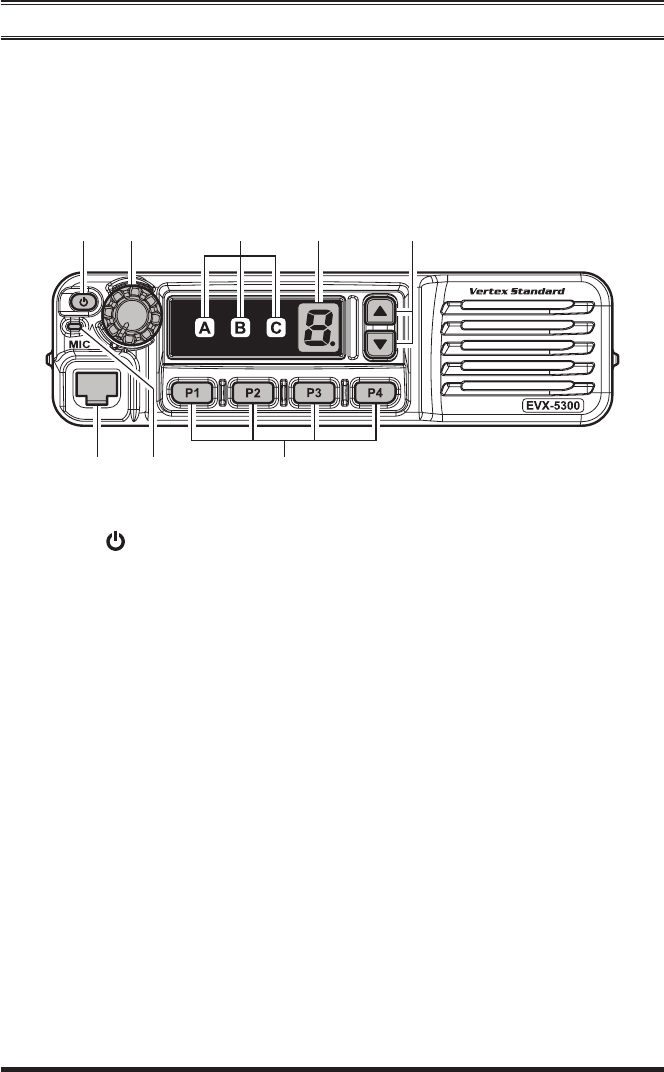
controls & connectors
Front Panel
Important! - All buttons located on the Front Panel are Programmable Function
(PF) keys, congured according to your network requirements and programmed
by your Vertex Standard dealer. The instructions below describe a typically-cong-
ured radio.
PWR ( ) Button
Press and hold in this button for 2 seconds to toggle the transceiver’s power
“on” and “off”.
VOL Knob
Turn this control clockwise to increase the volume.
Microphone Jack
Connect the microphone plug to this jack.
TX/BUSY Indicator
Indicates transceiver’s Transmit/Receive Status.
[P1] - [P4] Keys (Programmable Function Keys)
These keys can be set up for special applications, such as High/Low power
selection, Monitor, Talk-Around, etc., as determined by your network require-
ments and programmed by your Vertex Standard dealer.
[]/[] Keys (Programmable Function Keys)
In the factory default, pressing either key changes the current channel.

EVX-5300 OpErating Manual
3
controls & connectors
transceIver status IndIcator
Channel Number Indicator
Indicates the operating channel.
Transceiver Status Indicator
The “A”, “B”, and “C” indicators show current transceiver status, which can
be customized via programming by your Vertex Standard dealer to meet your
communications/network requirements. The possible these indicators are ex-
plained below.
status
IndIcator descrIptIon
A B C
MONI This indicator is illuminated constantly when the
signaling feature is disabled. The indicator blinks
while the audio is passing normally.
SCAN CH Illuminates the indicator when the scan enabled
channel is recalled
Low Power Illuminates the indicator when the radio’s transmit-
ter is set to the “Low Power” mode
TA (Talk Around)Illuminates the indicator when the “Talk Around”
function is activated.
Privacy (Digital)
Encryption (Analog)
Illuminates the indicator when the “Privacy” (Digital
mode) or “Voice Scrambler” (Analog mode) func-
tion is enabled.
Emergency Illuminates the indicator when the “Emergency”
feature is activated.
Horn Alert Illuminates the indicator when the “Horn Alert” fea-
ture is activated.
PA (Public Address)Illuminates the indicator when the radio is turned
to a PA amplier.
Lock Illuminates the indicator when the “Lock” feature is
activated.
ACC2 Illuminates the indicator when the output port “2”
on the Accessory Connector is turned to “ON”.
RFC Illuminates the indicator when the radio is in the
“Ready for Communication” condition while operat-
ing with the 2-Tone or 5-Tone signaling.
EVX-5300 OpErating Manual
4
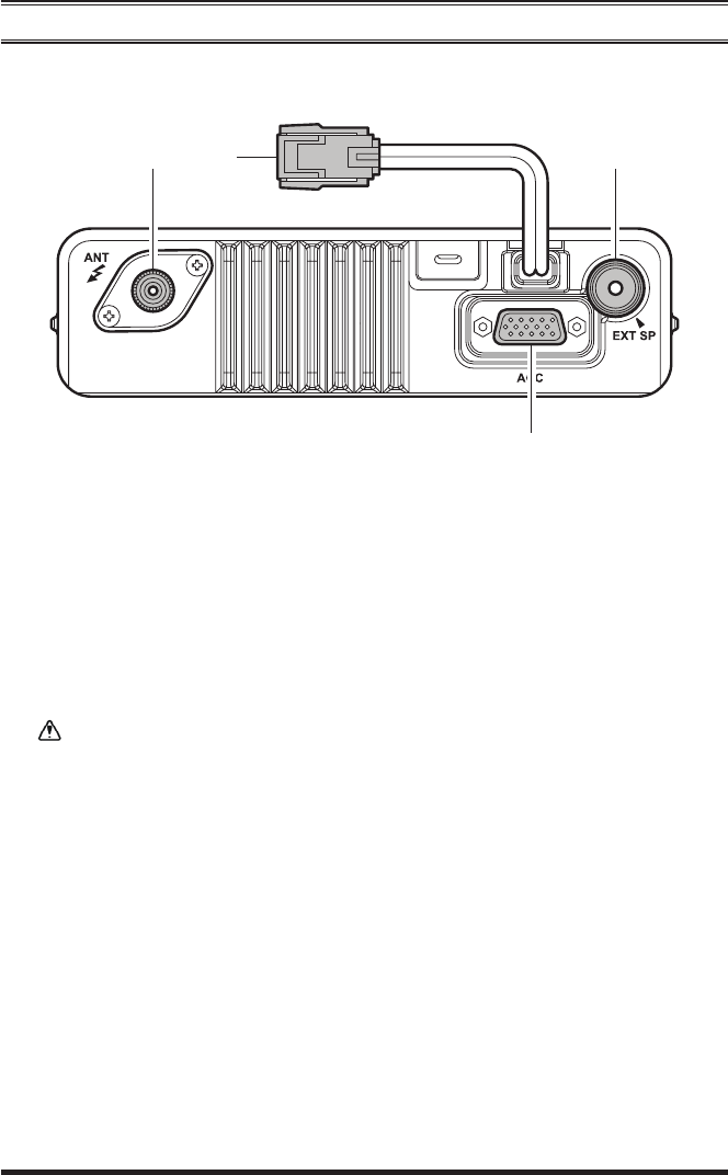
Rear Panel
controls & connectors
Antenna Jack
The 50-Ohm coaxial feedline to the antenna must be connected here, using a
mini-UHF plug.
13.6V DC Cable Pigtail with Connector
The supplied DC power cable must be connected to this 2-pin connector. Use
only the supplied fused cable, extended if necessary, for power connection.
Replace only with the same or equivalent type fuse.
External Speaker Jack
An external loudspeaker may be connected to this 2-contact, 3.5-mm mini-
phone jack.
Caution: Do not connect either wire of this line to ground, and be certain that
the speaker has adequate capability to handle the audio output (12 W) from
the radio.
D-Sub 15-Pin Accessory Connector
External TX audio line input, PTT (Push To Talk), Squelch, and external RX
audio line output signals may be obtained from this connector for use with ac-
cessories such as data transmission/reception modems, and external Channel
control input etc.

EVX-5300 OpErating Manual
5
BasIc operatIon
Important! - Before turning on the radio the rst time, conrm that the power con-
nections have been made correctly and that a proper antenna is connected to the
antenna jack.
Switching Power ON/OFF
Press and hold in the PWR( ) button for 2 seconds to turn the radio on. The
channel number indicator will indicate the operating channel.
Press the []/[] key to choose the desired operating channel. The radio an-
nounces the channel number, if the Channel Announcement Feature is enabled
via the clone editor software.
Setting the Volume
Turn the VOL knob clockwise to increase the volume, and counterclockwise
to decrease it.
Transmitting
To transmit, monitor the channel and make sure it is clear.
Press the PF key which is programmed to the Monitor feature to listen for
channel activity.
When receiving a call, transmit only after the incoming call ends. The radio
cannot receive a call and transmit simultaneously.
Press the PTT switch.
If the channel is clear, the TX/BUSY indicator will glow red (on the Analog
Channel) or blue (on the Digital Channel). The radio is now transmitting.
While holding in the PTT switch, speak across the face of the microphone in
a clear and normal voice. For best transmission, hold the microphone about
1-1/2 to 2 inches (4 ~ 5 cm) away from your mouth. Release the PTT switch
to receive.
If the BCLO (Busy Channel Lockout) feature has been programmed on an ana-
log channel, the radio will not transmit when a carrier is present. Instead, the
radio will generate short beep three times. Release the PTT switch and wait for
the channel to be clear of activity.
If the BTLO (Busy Tone Lockout) feature has been programmed on an analog
channel or CCLO (Color Code Lockout) feature has been programmed on
a digital channel, the radio can transmit only when there is no carrier being
received or when the carrier being received includes the correct tone (CTCSS
tone or DCS code) on an analog channel or correct code on a digital channel.

EVX-5300 OpErating Manual
6
Transmit Time-Out Timer
If the selected channel has been programmed for automatic time-out, you must
limit the length of each transmission. While transmitting, a beep will sound 10 sec-
onds before time-out. Another beep will sound just before the deadline; the red “TX”
indicator will disappear and transmission will cease soon thereafter. To resume
transmitting, you must release the PTT switch and wait for the “penalty timer” to
expire (if you press the PTT switch before this timer expires, the timer restarts,
and you will have to wait another “penalty” period).
Key Lock
In order to prevent accidental operating function/feature change or inadvertent
transmission, various aspects of the front panel’s keys may be locked out.
To activate the Locking feature, press and hold in the [P1] key while turning the
radio on. To disable the Locking feature, repeat this power-on procedure.
advanced operatIon
Programmable Function (PF) Keys
The EVX-5300 Series includes six Programmable Function (PF) keys. These PF
keys can be customized, via programming by your Vertex Standard dealer, to meet
your communications/network requirements.
The possible PF key programming features are illustrated on the next page, and
these functions are explained beginning after page 8. For further details, contact
your Vertex Standard dealer.
In this chapter, the following icons are used to indicate features supported in either
the “Analog” mode or “Digital” mode:
: Indicates a “Analog” mode only feature.
: Indicates a “Digital” mode only feature.
For features that are available in both “Analog” and “Digital” modes, no icon is
shown.
For future reference, check the box next to each function that has been assigned to
the PF key on your particular radio, and keep it handy.
BasIc operatIon

EVX-5300 OpErating Manual
7
FunctIon
programmaBle Key
(press Key/press & Hold Key)
mIcropHone Key
(press Key/press & Hold Key)
P1 P2 P3 P4 A B C D Ü#
None /////////// /
Monitor ////////////
Monitor -Momentarily- /-- /-- /-- /-- /-- /-- /-- /-- /-- /-- /-- /--
Lamp ////////////
Low Power ////////////
Privacy / Encryption ////////////
SQL OFF /////// / ////
SQL OFF -Momentarily- /-- /-- /-- /-- /-- /-- /-- /-- /-- /-- /-- /--
Beep Off ////////////
AF Minimum Volume ////////////
CH Announcement ////////////
Whisper ////////////
VOX ////////////
VOX Anti-Trip ////////////
Horn Alert ////////////
PA (Public Address)////////////
EXT ACC 1 /-- /-- /-- /-- /-- /-- /-- /-- /-- /-- /-- /--
EXT ACC 2 ////////////
Emergency /-- /-- /-- /-- /-- /-- /-- /-- /-- /-- /-- /--
Lone Worker ////////////
CH Up ////////////
CH Down ////////////
PRI-2 Set ////////////
PRI-2 Disable ////////////
PRI-2 ////////////
Direct CH 1 ////////////
Direct CH 2 ////////////
Direct CH 3 ////////////
Direct CH 4 ////////////
Scan ////////////
Dual Watch ////////////
FM Scan (Follow-Me Scan)////////////
SCAN Set ////////////
TA Scan ////////////
Talk Around (TA)////////////
RESET ////////////
Call 1 ////////////
Call 2 ////////////
Call 3 ////////////
Call 4 ////////////
Call 5 ////////////
Speed Dial ////////////
Call ////////////
Duty ////////////
TX Save Disable ////////////
Lock ////////////
advanced operatIon
EVX-5300 OpErating Manual
8
Description of Operating Functions
monItor
Press (or press and hold) the assigned PF key to cancel any signaling features.
monItor -momentarIly-
Cancel any signaling features while pressing the assigned PF key.
lamp
Press (or press and hold) the assigned PF key to toggle the back light of the key-
pad “On” and “Off”.
low power
Press (or press and hold) the assigned PF key to set the radio’s transmitter to the
“Low Power” mode. Press (or press and hold) the PF key again to return to “High
Power” operation when in difcult terrain.
When the radio’s transmitter is set to “Low Power” mode, the Transceiver Status
Indicator (“A”, “B” or “C”) will illuminate, if the “Low Power” status is assigned
to one of the Transceiver Status Indicator.
prIvacy
Press (or press and hold) the assigned PF key to toggle the Privacy feature “On”
and “Off”. The Privacy feature initiates an encryption algorithm that will protect
your communication from unauthorized eavesdropping.
When the Privacy feature is activated, the Transceiver Status Indicator (“A”, “B”
or “C”) will illuminate, if the “Privacy” status is assigned to one of the Transceiv-
er Status Indicator.
encryptIon
When the Voice Scrambler feature is enabled, press (or press and hold) the as-
signed PF key to toggle the voice encryption “On” and “Off”.
When the Voice Scrambler feature is activated, the Transceiver Status Indicator
(“A”, “B” or “C”) will illuminate, if the “Encryption” status is assigned to one of
the Transceiver Status Indicator.
sQl oFF
Press (or press and hold) the assigned PF key to open the SQL to hear background
noise (unmute the audio).
advanced operatIon

EVX-5300 OpErating Manual
9
sQl oFF -momentarIly-
Opens the SQL to hear background noise (unmute the audio) while pressing the
assigned PF key.
Beep oFF
Press (or press and hold) the assigned PF key to disable the radio beeps and the
channel announcement (if activated) temporarily. Again press (or press and hold)
the assigned PF key to enable the radio beeps and the channel announcement.
aF mInImum volume
Press (or press and hold) the assigned PF key to reduce the audio output to the
(lower) level programmed by your Vertex Standard dealer.
cH announcement
Press (or press and hold) the assigned PF key to select the channel change conr-
mation between “beep” and “announcement”.
wHIsper
Press (or press and hold) the assigned PF key to increase the microphone gain;
thus you can speak in a low voice (whisper) temporarily. Again press (or press and
hold) the assigned PF key to resume normal microphone gain.
voX
Press (or press and hold) the assigned PF key to turn the VOX function “On”
or “Off”. You may disable the VOX function temporarily by pressing the PTT
switch.
voX antI-trIp
Press (or press and hold) the assigned PF key to toggle the VOX Anti-Trip feature
“On” and “Off”. When the VOX Anti-Trip feature is set to “On”, the transceiver
does not activate the transmitter section from the receiver audio and own beep
sound.
Horn alert
Press (or press and hold) the assigned PF key to turn the Horn Alert function “On”
or “Off”. If you receive a call from the base station with the signaling, horn alert
will be activated and your vehicles horn will sound.
When the Horn Alert function is activated, the Transceiver Status Indicator (“A”,
“B” or “C”) will illuminate, if the “Horn Alert” status is assigned to one of the
Transceiver Status Indicator.
advanced operatIon

EVX-5300 OpErating Manual
10
advanced operatIon
pa (puBlIc address)
Press (or press and hold) the assigned PF key to use the transceiver as a PA ampli-
er. The Public Address can be used even while scanning and receiving a call.
When the Public Address function is activated, the Transceiver Status Indicator
(“A”, “B” or “C”) will illuminate, if the “Public Address” status is assigned to
one of the Transceiver Status Indicator.
eXt acc 1
Activates the output port “1” of the D-Sub 15-pin Accessory Connector while
pressing the assigned PF key.
eXt acc 2
Press (or press and hold) the assigned PF key to toggle the output port “2” of the
D-Sub 15-pin Accessory Connector “On” and “Off”.
emergency
The EVX-5300 series includes an “Emergency” feature in either analog or digital
modes, which may be useful for alerting another party monitoring on the same fre-
quency as your transceiver’s channel.
Press the assigned PF key to initiate an emergency call on the pre-dened channel.
For further details contact your Vertex Standard dealer.
When the Emergency feature is activated, the Transceiver Status Indicator (“A”,
“B” or “C”) will illuminate, if the “Emergency” status is assigned to one of the
Transceiver Status Indicator.
lone worKer
Press (or press and hold) the assigned PF key to toggle the Lone Worker feature
“On” and “Off”.
The Lone Worker feature is designed to emit an alarm for 30 seconds when the
Lone Worker Timer (programmed by your Vertex Standard dealer) has expired. If
the user does not reset the timer by pressing the PTT switch, the radio switches to
the Emergency mode.
cH up/down
Press (or press and hold) the assigned PF key (generally the []/[] key) to se-
lect a different channel.

EVX-5300 OpErating Manual
11
prI-2 set
Press (or press and hold) the assigned PF key to toggle the current channel to the
priority channel 2 “enable” and “disable”.
prI-2 dIsaBle
Press (or press and hold) the assigned PF key to disable the priority channel 2 of
the group temporarily.
prI-2
Press (or press and hold) the assigned PF key to recall the pre-programmed PRI-2
(Priority-2) Channel directly. This is pre-programmed by your Vertex Standard
dealer.
dIrect cH 1 to dIrect cH 4
Press (or press and hold) the assigned PF key to recall the pre-programmed chan-
nel directly. This is pre-programmed by your Vertex Standard dealer.
scan
The Scanning feature is used to monitor multiple channels programmed into the
transceiver. While scanning, the transceiver will check each channel for the pres-
ence of a signal, and will stop on a channel if a signal is present. EVX-5300 series
can scan both digital and analog frequency programmed channels simultaneously.
To activate scanning:
Press (or press and hold) the assigned PF key to activate scanning.
The scanner will search the channels of each channel, looking for active ones;
it will pause each time it nds a channel on which someone is speaking.
Press (or press and hold) the assigned PF key again to disable scanning. Op-
eration will revert to the programmed revert channel.
Note: Your Vertex Standard dealer may have programmed your radio to stay on
one of the following channels if you press the PTT switch during the scanning
pause:
o “Scan Pause” channel (“Talk Back”)
o “Last Busy” channel
o “Priority-2” channel
o “User Programmed” channel (“Select Channel”)
o “Scan Start” channel
advanced operatIon

EVX-5300 OpErating Manual
12
advanced operatIon
dual watcH
The Dual Watch feature is similar to the SCAN feature, except that only two chan-
nels are monitored:
o The current operating channel; and
o The Priority-2 channel.
To activate Dual Watch:
Press (or press and hold) the assigned PF key.
The scanner will search the two channels; it will pause each time it nds a
channel on which someone is speaking.
To stop Dual Watch:
Press (or press and hold) the assigned PF key.
Operation will revert to the “Dual Watch Start” channel.
Fm-scan (Follow-me scan)
The FM-Scan feature checks a User-assigned Priority Channel regularly as you
scan the other channels. Thus, if only Channels 1, 3, and 5 (of the 8 available
channels) are designated for “Scanning,” the user may nonetheless assign Channel
2 as the “User-assigned” Priority Channel via the FM-Scan.
To activate the FM-Scan, first select the channel you want to designate as the
“User-Assigned Priority Channel” and press (or press and hold) the assigned PF
key. Then press (or press and hold) the Channel Up/Down key (generally the []/
[] key) to recall to the “Scanning Start” channel which has been programmed by
your dealer to activate the scanner. When the scanner stops on an “Active” chan-
nel, the User-assigned Priority Channel will automatically be checked every few
seconds; if activity is found on the User-assigned Priority Channel, the radio will
switch between it and the Dealer-Assigned Priority Channel, if any.
scan set
Press (or press and hold) the assigned PF key to add/delete the current channel to/
from your scanning list.
When you delete channel, the Transceiver Status Indicator (“A”, “B” or “C”) will
turn off, if the “SCAN CH” status is assigned to one of the Transceiver Status
Indicator. To restore a particular channel to your scanning list, press (or press and
hold) the assigned PF key again; the Transceiver Status Indicator will illuminates,
if the “SCAN CH” status is assigned to one of the Transceiver Status Indicator.
When the scanner is stopped, you may remove the channel from the scan list tem-
porarily by pressing (or press and holding) this key.

EVX-5300 OpErating Manual
13
ta scan
Press (or press and hold) the assigned PF key to toggle the TA (Talk Around) scan
feature “On” and “Off.”
While TA scan is enabled, the transceiver will search both the transmit and receive
frequencies. When a signal is encountered on the receive frequency, the trans-
ceiver will pause until the signal disappears. When a signal is encountered on the
transmit frequency, the transceiver will check for activity on the receive frequency
every few seconds (interval programmed by your Vertex Standard dealer).
Note: The TA Scan feature does not activate on the Simplex Channel.
talK around
Press (or press and hold) the assigned PF key to activate the Talk Around feature
when you are operating on duplex channel systems (separate receive and transmit
frequencies, utilizing a “repeater” station). The Talk Around feature allows you to
bypass the repeater station and talk directly to a station that is nearby. This feature
has no effect when you are operating on “simplex” channels, where the receive
and transmit frequencies are already the same.
When the Talk Around feature is activated, the Transceiver Status Indicator (“A”,
“B” or “C”) will illuminate, if the “Talk Around” status is assigned to one of the
Transceiver Status Indicator.
Note that your Vertex Standard may have made provision for “Talk Around” chan-
nels by programming “repeater” and “Talk Around” frequencies on two adjacent
channels. If so, the key may be used for one of the other Pre-Programmed Func-
tions.
Note: The Talk Around feature does not activate on the Simplex Channel.
reset
Press (or press and hold) the assigned PF key to reset the RFC (Ready for Com-
munication) condition.
call 1 to call 5
Press (or press and hold) the assigned PF key to send a pre-programmed call sig-
nal of the 2-Tone, 5-Tone, MDC1200®, or Digital Call.
advanced operatIon

EVX-5300 OpErating Manual
14
advanced operatIon
speed dIal
Press (or press and hold) the assigned PF key to prepare the “Speed Dial” func-
tion. Press the PTT switch within pre-dened period time of releasing the key to
send a pre-dened DTMF tone.
call
Press (or press and hold) the assigned PF key to send a 2-tone or 5-tone sequential
tone.
duty
Press (or press and hold) the assigned PF key to toggle the Duty function of the
2-tone, 5-tone, MDC1200®, or Digital Call decoder “On” and “Off”.
When the Duty function is set to “On”, the user will always hear (depending on
the sub-audio signaling) all trafc on the paging channel. The radio will sound the
paging alert when it receives the programmed 2-tone, 5-tone, MDC1200®, or Digi-
tal Call code.
When the Duty function is set to “Off”, the user will NOT hear normal radio traf-
c on the paging channel. The radio will sound the paging alert and unmute only
when it receives the programmed 2-tone, 5-tone, MDC1200®, or Digital Call code.
tX save dIsaBle
Press (or press and hold) the assigned PF key to disable the Transmit Saver, if you
are operating in a location where high power is almost always needed.
The Transmit Saver reduces the transmit power when a very strong signal from an
apparently nearby station is being received.
locK
Press (or press and hold) the assigned PF key to lock the various aspects of the
front panel’s keys. The precise lockout conguration must be programmed by your
Vertex Standard dealer.

EVX-5300 OpErating Manual
15
arts™ (auto range transpond system)
This system is designed to inform you when you and another ARTS™-equipped
station are within communication range.
During ARTS™ operation, when the radio receives an incoming ARTS™ signal,
a short beep will sound. If you move out of range for more than two minutes, your
radio senses that no signal has been received; a short triple-beep will sound. If you
subsequently move back into communication range, as soon as the other station
transmits, a short beep will sound again.
arts
II
™ (auto range transpond system)
The ARTSII™ system is enhanced feature of the ARTSII™ which can be nding
out the communication range of the radio individually by using the MDC-1200®
Encode/Decoder or Digital mode operation.
Note: EVX-5300 will be able to be decoded by display radios with ARTSII™ en-
abled, but will not be able to decode the other radios encode signals.

EVX-5300 OpErating Manual16
optIonal accessorIes
MH-67A8J Standard Microphone
MH-75A8J 16-Keypad Microphone
MD-12A8J Desktop Microphone
MLS-100 External Speaker (12 W Peak Power)
LF-6 Line Filter
CE142 PC Programming Software
CT-4 Programming Cable (Radio to Radio Clone Cable)
FIF-12 USB Programming Interface
CT-104A Connection Cable for FIF-12 (8-pin DIN 8-pin Modular)
Availability of accessories may vary; some accessories are supplied standard per
local requirements, others may be unavailable in some regions.
Check with your Vertex Standard Dealer for changes to this list.

DiSpoSal of your electroNic aND electric equipmeNt
Products with the symbol (crossed-out wheeled bin) cannot be disposed as
household waste.
Electronic and Electric Equipment should be recycled at a facility
capable of handling these items and their waste by products.
In EU countries, please contact your local equipment supplier representative
or service center for information about the waste collection system in your
country.
Part 15.21: Changes or modications to this device not expressly
approvedby VertexStandardcouldvoidtheuser’sauthorizationto
operatethisdevice.
Notice !
There are no owner-serviceable parts inside the transceiver. All service jobs
must be referred to an authorized Vertex Standard Service Representative.
Consult your Authorized Vertex Standard Dealer for installation of optional
accessories.
The AMBE+2TM voice coding Technology embodied in this product
is protected by intellectual property rights including patent rights,
copyrights and trade secrets of Digital Voice Systems, Inc. This voice
coding Technology is licensed solely for use within this Communications
Equipment. The user of this Technology is explicitly prohibited from
attempting to decompile, reverse engineer, or disassemble the Object Code,
or in any other way convert the Object Code into a human-readable form.
U.S. Pat. Nos. #5,870,405, #5,826,222, #5,754,974, #5,701,390,
#5,715,365, #5,649,050, #5,630,011, #5,581,656, #5,517,511, #5,491,772,
#5,247,579, #5,226,084 and #5,195,166.

Copyright 2013
Vertex Standard LMR, Inc.
All rights reserved.
No portion of this manual
may be reproduced
without the permission of
Vertex Standard LMR, Inc.
Vertex Standard LMR, Inc.