Vertex Standard USA 11153020 HANDHELD TRANSCEIVER User Manual 1
Vertex Standard USA, Inc. HANDHELD TRANSCEIVER 1
UserManual.wiki
>
Vertex Standard USA
>
11153020 User Manual
>
User Manual 1
Contents
1.
User Manual 1
2.
User Manual 2
User Manual 1
Navigation menu
Upload a User Manual
Namespaces
Wiki Guide
HTML
PDF
Info
Views
User Manual
Discussion / Help
Navigation
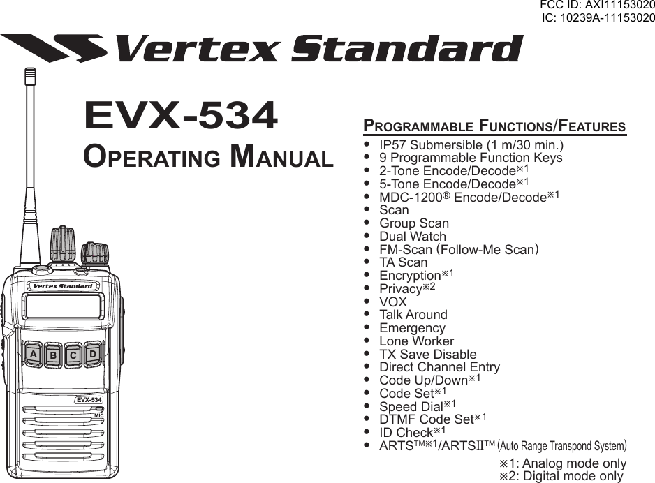
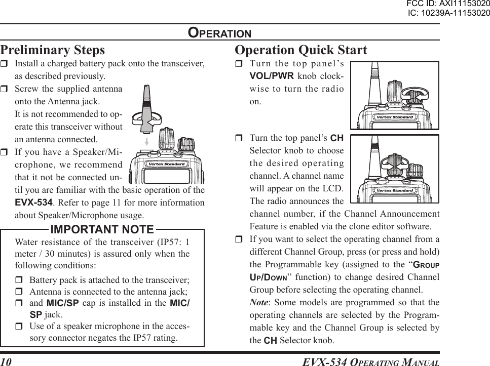
![EVX-534 OpErating Manual11opEratIon Rotate the VOL/PWR knob to set the volume le vel . I f no sign al is present on the analog channel, press and hold in the SIDE-1 button (under the PTT switch) more than 2 seconds; background noise will now be heard, and you may use this to set the VOL/PWR knob for the desired audio level. Press and hold the SIDE-1 button more than 2 seconds (or press the SIDE-1 button twice) to quiet the noise and resume nor-mal (quiet) monitoring. To transmit, monitor the channel and make sure it is clear. Press and hold the PTT switch. Speak into the microphone area of the front panel grille in a normal voice level. To re-turn to the Receive mode, release the PTT switch. Press the (Orange) TOP SEL key, SIDE-2 but-ton, or front panel’s pro-grammable keypad ([A], [B], [C] and [D] keys) to activate one of the pre-programmed func-tions which may have been enabled at the time of programming by the dealer. See the next sec-tion for details regarding feature availability for this radio. If a Speaker/Micro-phone is available, remove the plastic cap and its two mounting screws from the right side of the transceiver, then align the connector EVX-534AB C DDFCC ID: AXI11153020IC: 10239A-11153020](https://usermanual.wiki/Vertex-Standard-USA/11153020.User-Manual-1/User-Guide-2006078-Page-13.png)
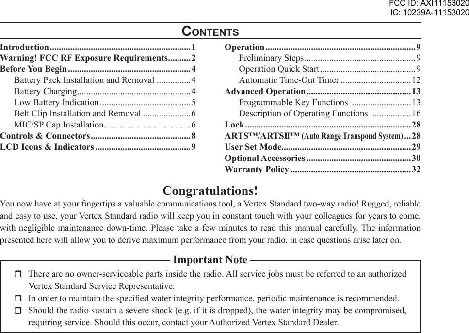
![EVX-534 OpErating Manual13advancEd opEratIonProgrammable Key FunctionsThe EVX-534 provides the seven programmable function (PF) keys: TOP SEL, SIDE-1, SIDE-2, [A], [B], [C] and [D] keys. These PF keys can be customized, via programming by your Vertex Stan-dard dealer, to meet your communications/network requirements.The possible PF key programming features are il-lustrated on the next page, and their functions are explained beginning after page 16. For further details, contact your Vertex Standard dealer.In this chapter, the following icons are used to indi-cate features supported in either the “Analog” mode or “Digital” mode:: Indicates a “Analog” mode only feature.: Indicates a “Digital” mode only feature.For features that are available in both “Analog” and “Digital” modes, no icon is shown.For future reference, check the box next to each func-tion that has been assigned to the PF key on your particular radio, and keep it handy.FCC ID: AXI11153020IC: 10239A-11153020](https://usermanual.wiki/Vertex-Standard-USA/11153020.User-Manual-1/User-Guide-2006078-Page-15.png)
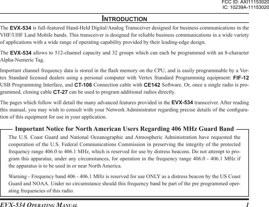
![EVX-534 OpErating Manual14advancEd opEratIonFunctIonprogrammaBlE KEY (prEss KEY / prEss and Hold KEY)TOP SEL SIDE-1 SIDE-2 [A] [B] [C] [D]None / / / / / / /Monitor / / / / / / /Monitor -Momentarily- /--- /--- /--- /--- /--- /--- /---Light / / / / / / /Low Power / / / / / / /Privacy / Encryption / / / / / / /SET / / / / / / /SQL OFF / / / / / / /SQL OFF -Momentarily- /--- /--- /--- /--- /--- /--- /---SQL Set / / / / / / /Beep Off / / / / / / /AF Min Volume / / / / / / /CH Announcement / / / / / / /Whisper / / / / / / /VOX / / / / / / /VOX Set / / / / / / /VOX Anti-Trip / / / / / / /Emergency /--- /--- /--- /--- /--- /--- /---Lone Worker / / / / / / /Group Up / / / / / / /Group Down / / / / / / /Channel Up / / / / / / /Channel Down / / / / / / /Speed Channel Up --- / --- / --- / --- / --- / --- / --- /Speed Channel Down --- / --- / --- / --- / --- / --- / --- /RPI-2 Set / / / / / / /PRI-2 Disable / / / / / / /PRI-2 / / / / / / /Direct CH 1 / / / / / / /Direct CH 2 / / / / / / /Direct CH 3 / / / / / / /Direct CH 4 / / / / / / /Direct CH Entry / / / / / / /Scan / / / / / / /Group Scan / / / / / / /Dual Watch / / / / / / /FM-Scan / / / / / / /FCC ID: AXI11153020IC: 10239A-11153020](https://usermanual.wiki/Vertex-Standard-USA/11153020.User-Manual-1/User-Guide-2006078-Page-16.png)
![EVX-534 OpErating Manual15advancEd opEratIonFunctIonprogrammaBlE KEY (prEss KEY / prEss and Hold KEY)TOP SEL SIDE-1 SIDE-2 [A] [B] [C] [D]Scan Set / / / / / / /Group Scan Set / / / / / / /TA Scan / / / / / / /Talk Around / / / / / / /Reset / / / / / / /Call 1 / / / / / / /Call 2 / / / / / / /Call 3 / / / / / / /Call 4 / / / / / / /Call 5 / / / / / / /Code Up / / / / / / /Code Down / / / / / / /Code Set / / / / / / /Speed Dial / / / / / / /Call / / / / / / /Status Set / / / / / / /Status Up / / / / / / /Status Down / / / / / / /Status Check / / / / / / /Duty / / / / / / /ID Check / / / / / / /ARTS Login / / / / / / /TX Save Disable / / / / / / /Lock / / / / / / /FCC ID: AXI11153020IC: 10239A-11153020](https://usermanual.wiki/Vertex-Standard-USA/11153020.User-Manual-1/User-Guide-2006078-Page-17.png)
![EVX-534 OpErating Manual17advancEd opEratIonsql oFF Press, (or press and hold), the assigned PF key to open the SQL to hear background noise (unmute the audio).sql oFF -momEntarIlY- Opens the SQL to hear background noise (unmute the audio) while pressing the assigned PF key.sql sEt You can manually adjust the squelch level using this function: Press, (or press and hold), the assigned PF key. A tone will sound, and the current squelch level will appear on the display. Press the SIDE-1/SIDE-2 buttons (or [A]/[B] keys) to select the desired squelch level. Available selections are “SQLLV OP (Open)”, “SQLLV TH (Threshold)”, “SQLLV NM (Normal)” and “SQLLV TI (Tight)”. Press the [D] key to store the new setting. The display indicates “- SET -” briey, then reverts to the normal channel indication. You may cancel the new setting by pressing the [C] key. In this case, the display indicates “- CANCEL -” briey.BEEp oFFPress, (or press and hold), the assigned PF key, the display indicates “BEEP OFF” briefly, and disable the radio beeps and the channel announcement (if ac-tivated) temporarily. Again press, (or press and hold), the assigned PF key, the display indicates “BEEP ON” briey, and enable the radio beeps and the chan-nel announcement.aF mInImum volumEPress, (or press and hold), the assigned PF key to reduce the audio output to the (lower) level pro-grammed by your Vertex Standard dealer.cH announcEmEntPress, (or press and hold), the assigned PF key to se-lect the channel change conrmation between “beep” (indicates “BEEP” briey) and “announcement” (in-dicates “ANNOUNCE” briey).FCC ID: AXI11153020IC: 10239A-11153020](https://usermanual.wiki/Vertex-Standard-USA/11153020.User-Manual-1/User-Guide-2006078-Page-19.png)
![EVX-534 OpErating Manual20advancEd opEratIondIrEct cH EntrYYou can recall the desired channel directly using this function: Press, (or press and hold), the assigned PF key. A tone will sound, and the current group/channel will appear on the display. Select the desired digit of the group number and channel number using the [A]/[B] keys, then change the number using the SIDE-1/SIDE-2 buttons. Press the [D] key to store the new setting. The display indicates “- SET -” briey, then reverts to the normal channel indication. You may cancel the new setting by pressing the [C] key. In this case, the display indicates “- CANCEL -” briey.scanThe Scanning feature is used to monitor multiple signals programmed into the transceiver. While scan-ning, the transceiver will check each channel for the presence of a signal, and will stop on a channel if a signal is present. EVX-534 can scan both digital and analog frequency programmed channels simultane-ously.To activate scanning: Press, (or press and hold), the assigned PF key to activate scanning. The scanner will search the channels of each channel, looking for active ones; it will pause each time it nds a channel on which someone is speaking. Press again, (or press and hold again), the as-signed PF key to disable scanning. Operation will revert to the programmed revert channel.Note: Your dealer may have programmed your radio to stay on one of the following channels if you press the PTT switch during scanning pause: “Scan Pause” channel (“Talk Back”) “Last Busy” channel “Priority-2” channel “User Programmed” channel (“Select Channel”)The channel which dened in the CH Selector knob.FCC ID: AXI11153020IC: 10239A-11153020](https://usermanual.wiki/Vertex-Standard-USA/11153020.User-Manual-1/User-Guide-2006078-Page-22.png)
![EVX-534 OpErating Manual24rEsEt Press (or press and hold) the assigned PF key to reset the RFC (Ready for Communication) condition.call 1 to call 5Press, (or press and hold), the assigned PF key to send a pre-dened 2-tone Sequential Tone Group (on an analog channel) or a pre-dened Digital Contact List (on a digital channel).codE up/doWn Press, (or press and hold), the assigned PF key to select a 2-Tone or 5-Tone encode code from the pre-programmed encode list.codE sEt You can change the desired digit of the 5-Tone en-code code using this function: Press, (or press and hold), the assigned PF key. Select the desired digit using the [A]/[B] keys, then change the number using the SIDE-1/SIDE-2 buttons. Press the [D] key to store the new setting. The display indicates “- SET -” briey, then reverts to the normal channel indication. You may cancel the new setting by pressing the [C] key. In this case, the display indicates “- CANCEL -” briey.spEEd dIal Your Vertex Standard dealer may have pre-pro-grammed Auto-Dial telephone number memories into your radio.To dial a number, press, (or press and hold), the as-signed PF key, then press the [A]/[B] keys to select the Auto-Dial memory number list provided by your Vertex Standard dealer or Network Administrator, then press the PTT switch. The DTMF tones sent dur-ing the dialing sequence will be heard in the speaker.call Press, (or press and hold), the assigned PF key to send a 2-tone or 5-tone sequential tone.advancEd opEratIonFCC ID: AXI11153020IC: 10239A-11153020](https://usermanual.wiki/Vertex-Standard-USA/11153020.User-Manual-1/User-Guide-2006078-Page-26.png)
![EVX-534 OpErating Manual25status sEt You can change the 5-tone status code using this function: Press, (or press and hold), the assigned PF key to change the 5-tone status code. Select the desired digit using the [A] key, then change the number using the [B]/[C] keys. Press the [D] key to store the new number to the 5-tone status code.status up/doWn Press, (or press and hold), the assigned PF key to select a 5-tone status code from the pre-dened status list.status cHEcK Press, (or press and hold), the assigned PF key to check the 5-tone receive status code. When you press this key, the display will indicate the “Message” cor-responding to the receive status condition per the pre-dened status list.dutYPress, (or press and hold), the assigned PF key to toggle the Duty function of the 2-tone, 5-tone, MDC1200® or Digital Call decoder “On” and “Off”.When the Duty function is set to “On”, the display in-dicates “DUTY ON” briey and the user will always hear (depending on the sub-audio signaling) all traf-c on the paging channel. The radio will sound the paging alert when it receives the programmed 2-tone, 5-tone, MDC1200® or Digital Call code.When the Duty function is set to “Off”, the display indicates “DUTY OFF” briefly and the user will NOT hear normal radio traffic on the paging chan-nel. The radio will sound the paging alert and unmute only when it receives the programmed 2-tone, 5-tone, MDC1200® or Digital Call code.advancEd opEratIonFCC ID: AXI11153020IC: 10239A-11153020](https://usermanual.wiki/Vertex-Standard-USA/11153020.User-Manual-1/User-Guide-2006078-Page-27.png)
![EVX-534 OpErating Manual26Id cHEcK This function allows logged ID of the DTMF Signal-ing and 5-tone Signaling to be reviewed and relayed (5-tone Signaling only) to a specic station: Press, (or press and hold), the assigned PF key to display the logged ID of the DTMF Signaling and 5-tone Signaling. Press the [A] key to select the category (“DTMF Signaling” or “5-tone Signaling”) to be reviewed, then press the SIDE-1/SIDE-2 buttons to select the ID. Press the [B] key to toggle the display between the “ID code display” and “Tag display”. Press the [C] key to send the Call back, when recalling the ID of the “5-tone Signaling”, if de-sired. You may cancel the Call back sending by press-ing the [C] key. In this case, the display indicates “- CANCEL -” briey.arts logInThis function enable the displaying the logged ID of the MDC1200® ARTS™ (or ARTSII™). Press, (or press and hold), the assigned PF key to display the number of the logged station of the MDC1200® ARTS™ (or ARTSII™) for ve seconds, and then the display indicates the “ID number” of the logged station. Press the SIDE-1/SIDE-2 buttons to indicate the “ID number” of other stations, if needed. Press the [C] key to resume normal display.advancEd opEratIonFCC ID: AXI11153020IC: 10239A-11153020](https://usermanual.wiki/Vertex-Standard-USA/11153020.User-Manual-1/User-Guide-2006078-Page-28.png)
![EVX-534 OpErating Manual29usEr sEt modEThe EVX-534 includes a “User Set” (Menu) Mode which allows the user to dene or congure various settings, such as Squelch, Display contrast, etc. To activate the “User Set” (Menu) Mode: Press the assigned PF key assigned to the “SET” function. Select the User Set Mode item you wish to change using the [A]/[B] keys, then use the SIDE-1/SIDE-2 keys to adjust the setting of the selected item.sEt modE ItEm dEscrIptIon avaIlaBlE valuEsSQL Sets the Squelch level. SQL OP (Open),SQL TH (Threshold),SQL NM (Normal),SQL TI (Tight)Beep Enables/Disables the Key Beeper. BEEP ON, BEEP OFFBell Enables/Disables the Bell function (Alert tone activated by incoming signaling). BELL ON, BELL OFFLight Enables/Disables the back light of the display and keypad. LIGHT ON, LIGHT OFFKey Enables/Disables the Key Lock function. KEY FRE (Free), KEY LCK (Lock)PTT Enables/Disables the PTT Lock function. PTT FRE (Free), PTT LCK (Lock)DIMMER Sets the LCD Brightness level. DIMM 1, DIMM 2, DIMM 3Scan Engages/Disengages Scanning. SCAN ON,SCAN FM (Follow-Me Scan),SCAN GRP (Group Scan),SCAN OFFDW Engages/Disengages Dual Watch. DW ON, DW OFFAF Sets the minimum Audio Volume level. AF 000 ~ AF 255CONTRAST Sets the LCD Contrast level. CONTR 00 ~ 15TX Save Enables/Disables the TX Save function. TXSV ON, TXSV OFF Press the [D] key to store the new conguration. You may cancel the selection by pressing the [C] key. Press the programmable key assigned to the “SET” function to exit to normal operation.FCC ID: AXI11153020IC: 10239A-11153020](https://usermanual.wiki/Vertex-Standard-USA/11153020.User-Manual-1/User-Guide-2006078-Page-31.png)