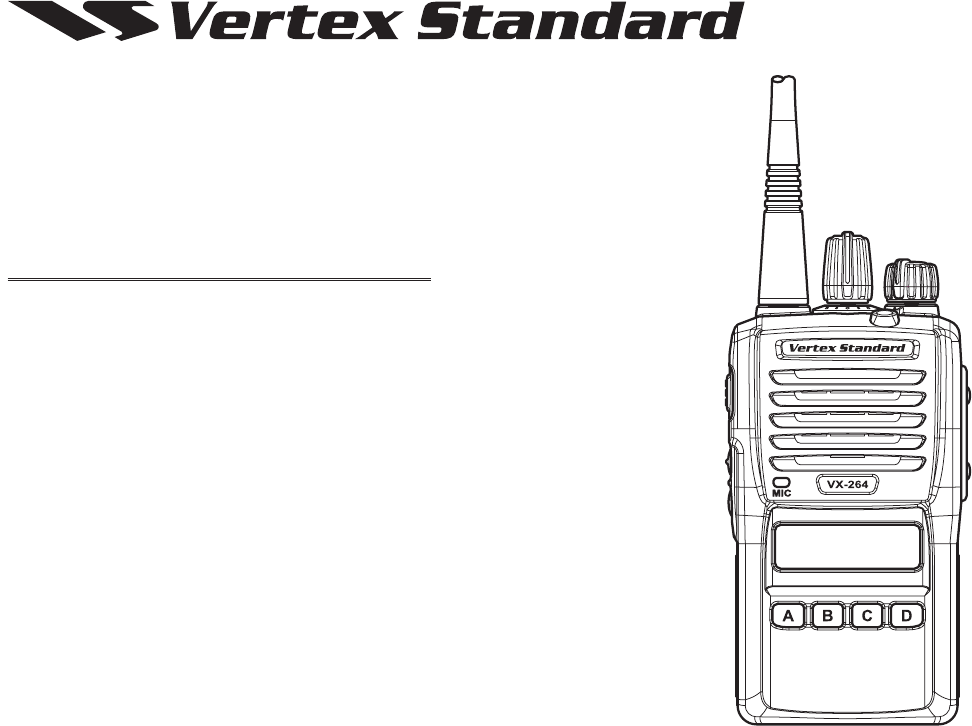
Vertex Standard USA 11274620 2-WAY PORTABLE RADIO User Manual
Vertex Standard USA, Inc. 2-WAY PORTABLE RADIO
User Manual
Programmable Functions/Features
IP55Submersible
AvailableSixProgrammableFunctionKeys
2-ToneEncode/Decode
5-ToneEncode/Decode
MDC-1200®Encode(ANIEncode)
Scan
GroupScan
DualWatch
Follow-MeScan
TalkAroundScan
Encryption
VOX
TalkAround
Emergency
LoneWorker
TXSaveDisable
CodeUp/Down
CodeSet
SpeedDial
Duty
Lock
ARTS™(AutoRangeTranspondSystem)
VX-264
oPerating manual
FCC ID: AXI11274620
IC: 10239A-11274620
Vertex Standard LMR, Inc.

BatteryPackInstallationandRemoval....................... 6
BatteryCharging......................................................... 6
LowBatteryIndication................................................ 7
BeltClipInstallationandRemoval............................. 8
MIC/SPCapInstallation............................................. 8
PreliminarySteps...................................................... 12
OperationQuickStart................................................ 12
AutomaticTime-OutTimer....................................... 14
ProgrammableKeyFunctions.................................. 15
DescriptionofOperatingFunctions......................... 18
contents
Younowhaveatyourngertipsavaluablecommunicationstool,aVertexStandardtwo-wayradio!Rugged,reliableand
easytouse,yourVertexStandardradiowillkeepyouinconstanttouchwithyourcolleaguesforyearstocome,withnegli-
giblemaintenancedown-time.Pleasetakeafewminutestoreadthismanualcarefully.Theinformationpresentedherewill
allowyoutoderivemaximumperformancefromyourradio,incasequestionsariselateron.
r Therearenoowner-serviceablepartsinsidetheradio.AllservicejobsmustbereferredtoanauthorizedVertex
StandardServiceRepresentative.
r Inordertomaintainthespeciedwaterintegrityperformance,periodicmaintenanceisrecommended.
r Shouldtheradiosustainasevereshock(e.g.ifitisdropped),thewaterintegritymaybecompromised,requiring
service.Shouldthisoccur,contactyourAuthorizedVertexStandardDealer.
FCC ID: AXI11274620
IC: 10239A-11274620
Vertex Standard LMR, Inc.
VX-264 Operating Manual 1
TheU.S.CoastGuardandNationalOceanographicandAtmosphericAdministrationhaverequestedthecooperation
oftheU.S.FederalCommunicationsCommissioninpreservingtheintegrityoftheprotectedfrequencyrange406.0
to406.1MHz,whichisreservedforusebydistressbeacons.Donotattempttoprogramthisapparatus,underany
circumstances,foroperationinthefrequencyrange406.0-406.1MHziftheapparatusistobeusedinornearNorth
America.
Warning-Frequencyband406-406.1MHzisreservedforuseONLYasadistressbeaconbytheUSCoastGuard
andNOAA.Undernocircumstanceshouldthisfrequencybandbepartofthepreprogrammedoperatingfrequencies
ofthisradio.
introduction
TheVX-264isfull-featuredHand-HeldAnalogTransceiverdesignedforbusinesscommunicationsintheVHF/UHFLand
Mobilebands.Thistransceiverisdesignedforreliablebusinesscommunicationsinawidevarietyofapplicationswitha
widerangeofoperatingcapabilityprovidedbytheirleading-edgedesign,andallowsupto128-channelcapacitywithina
maximum8groups.Eachchannelcanbeprogrammedwithan8-characterAlpha-NumericTag.
Importantchannelfrequencydataisstoredintheashmemory,andiseasilyprogrammablebyaVertexStandardlicensed
dealersusingapersonalcomputerwithVertexStandardProgrammingequipment:FIF-12USBProgrammingInterface,and
CT-106ConnectioncablewithCE150Software.Or,onceasingleradioisprogrammed,cloningcableCT-27canbeused
toprogramadditionalradiosdirectly.
WedescribesthedetailsofthemanyadvancedfeaturesoftheVX-264inthismanual.Afterreadingthismanual,youmay
wishtoconsultwithyourNetworkAdministratorregardingprecisedetailsofthecongurationofthisequipmentforusein
yourapplication.
FCC ID: AXI11274620
IC: 10239A-11274620
Vertex Standard LMR, Inc.
2
VX-264 Operating Manual
Warning! Fcc rF exPosure requirements
ThisRadiohasbeentestedandcomplieswiththeFederalCommunicationsCommission(FCC)RFexposurelimitsforOc-
cupationalUse/Controlledexposureenvironment.Inaddition,itcomplieswiththefollowingStandardsandGuidelines:
r FCC96-326,GuidelinesforEvaluatingtheEnvironmentalEffectsofRadio-FrequencyRadiation.
r FCCOETBulletin65 Edition97-01(2001) SupplementC, EvaluatingCompliancewithFCCGuidelines forHuman
ExposuretoRadioFrequencyElectromagneticFields.
r ANSI/IEEEC95.1-1992,IEEEStandardforSafetyLevelswithRespecttoHumanExposuretoRadioFrequencyElec-
tromagneticFields,3kHzto300GHz.
r ANSI/IEEEC95.3-1992,IEEERecommendedPracticefortheMeasurementofPotentiallyHazardousElectromagnetic
Fields-RFandMicrowave.
ThisradiogeneratesRFelectromagneticenergyduringtransmitmode.Thisradioisdesignedforandclassiedas
Occupational Use Only,meaningitmustbeusedonlyduringthecourseofemploymentbyindividualsawareofthe
hazards,andthewaystominimizesuchhazards.ThisradioisnotintendedforusebytheGeneralPopulationinan
uncontrolledenvironment.
ToensurethatyourexposetoRFelectromagneticenergyiswithintheFCCallowablelimitsforoccupationaluse,
alwaysadheretothefollowingguidelines:
FCC ID: AXI11274620
IC: 10239A-11274620
Vertex Standard LMR, Inc.

VX-264 Operating Manual
3
Warning! Fcc rF exPosure requirements
FCC ID: AXI11274620
IC: 10239A-11274620
Vertex Standard LMR, Inc.
4
VX-264 Operating Manual
Warning! ic rss general requirement
english
r UnderIndustryCanadaregulations,thisradiotransmittermayonlyoperateusinganantennaofatypeandmaximum(or
lesser)gainapprovedforthetransmitterbyIndustryCanada.Toreducepotentialradiointerferencetootherusers,the
antennatypeanditsgainshouldbesochosenthattheequivalentisotropicallyradiatedpower(e.i.r.p.)isnotmorethan
thatnecessaryforsuccessfulcommunication.
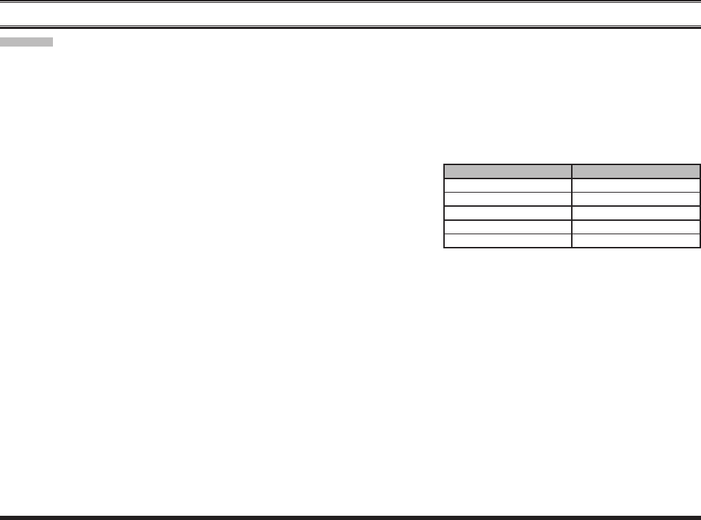
r Thisradiotransmitter(identifythedevicebycerticationnumber,ormodelnumberifCategoryII)hasbeenapproved
byIndustryCanadatooperatewith theantennatypeslistedattheright
with the maximum permissible gain and required antenna impedance
foreachantennatypeindicated.Antennatypesnotincludedin thislist,
havingagaingreaterthanthemaximumgainindicatedforthattype,are
strictlyprohibitedforusewiththisdevice.
VhF model uhF model
ATV-8A:2.15dBi,50-ohm ATU-6A:2.15dBi,50-ohm
ATV-8B:2.15dBi,50-ohm ATU-6B:2.15dBi,50-ohm
ATV-8C:2.15dBi,50-ohm ATU-6C:2.15dBi,50-ohm
ATV-6XL:2.15dBi,50-ohm ATU-6F:2.15dBi,50-ohm
ATU-6AF:2.15dBi,50-ohm
FCC ID: AXI11274620
IC: 10239A-11274620
Vertex Standard LMR, Inc.
VX-264 Operating Manual
5
French
r Conformément à la réglementation d’Industrie Canada, le présent émetteur radio peut fonctionner avec une antenne
d’untypeetd’ungainmaximal(ouinférieur)approuvépourl’émetteurparIndustrieCanada.Danslebutderéduireles
risquesdebrouillageradioélectriqueàl’intentiondesautresutilisateurs,ilfautchoisirletyped’antenneetsongainde
sortequelapuissanceisotroperayonnéequivalente(p.i.r.e.)nedépassepasl’intensiténécessaireàl’établissementd’une
communicationsatisfaisante.
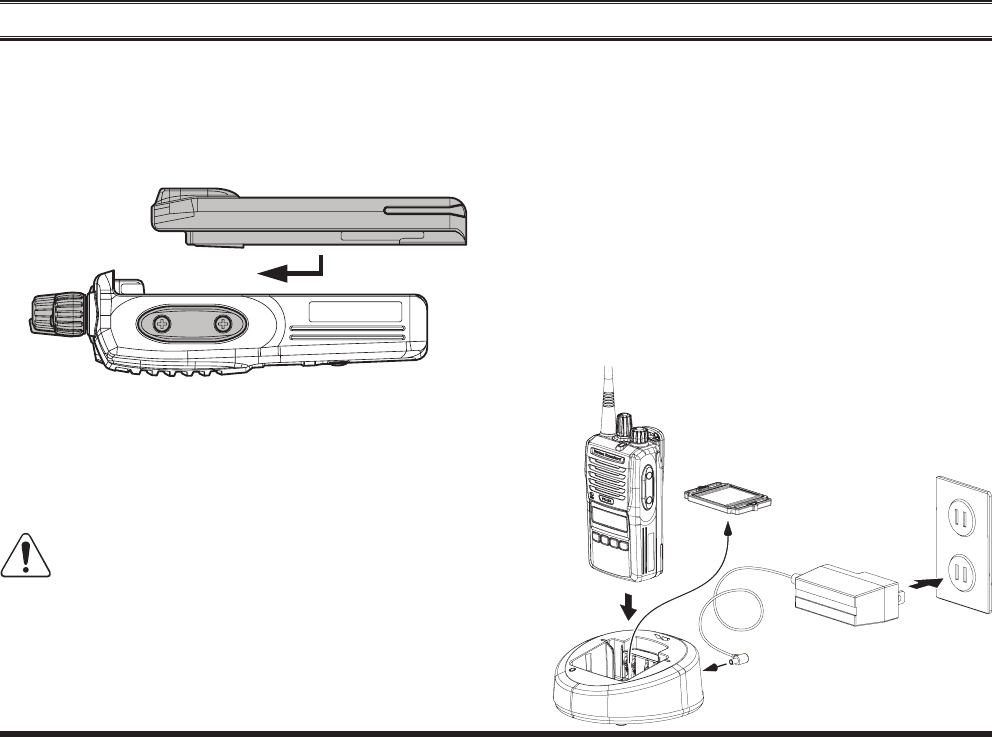
r Leprésentémetteurradio(identierledispositifparsonnumérodecerticationousonnumérodemodèles’ilfaitpar-
tiedumatérieldecatégorieI)aétéapprouvéparIndustrieCanadapour
fonctionneraveclestypesd’antenneénumérésdansledroitetayantun
gainadmissiblemaximaletl’impédancerequisepourchaquetyped’an-
tenne.Lestypesd’antennenoninclusdanscetteliste,oudontlegainest
supérieuraugain maximalindiqué,sontstrictementinterdits pourl’ex-
ploitationdel’émetteur.
Warning! ic rss general requirement
VhF modèle uhF modèle
ATV-8A:2.15dBi,50-ohm ATU-6A:2.15dBi,50-ohm
ATV-8B:2.15dBi,50-ohm ATU-6B:2.15dBi,50-ohm
ATV-8C:2.15dBi,50-ohm ATU-6C:2.15dBi,50-ohm
ATV-6XL:2.15dBi,50-ohm ATU-6F:2.15dBi,50-ohm
ATU-6AF:2.15dBi,50-ohm
FCC ID: AXI11274620
IC: 10239A-11274620
Vertex Standard LMR, Inc.
6
VX-264 Operating Manual
beFore You begin
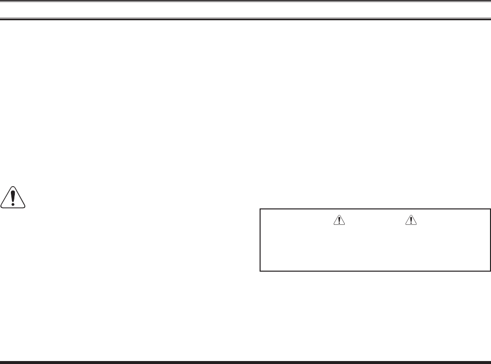
r To remove the battery, turn the radio off and remove
anyprotectivecases.SlidetheBatteryPackLatchon
the bottom of the radio toward the front panel while
slidingthebatterydownabout1/2inch(1.5cm).Then
liftthebatteryoutfromtheradio.
r Toinstallthebatterypack,alignthebatterypacktothe
radiowithanoffsetabout1/2inch(1.5cm)fromthe
topedgeofbatterycompartment,thenslidethebattery
packupwarduntilitlocksinplacewitha“Click.”
r RemovetheSpacerPlatefromthenestoftheoptional
CD-58 Desktop Charger, if the Battery Spacer is in-
stalled.
r InserttheDCplugfromtheoptionalPA-55AC
AdapterintotheDCjackontherearpaneloftheop-
tional CD-58 Desktop Charger, and then connect the
PA-55ACAdaptertotheAClineoutlet.
r InsertthebatterypackintotheCD-58DesktopChar-
gerwhilealigningtheslotsofthebatterypackwiththe
guidesinthenestoftheCD-58;refertothefollowing
illustrationfordetailsonproperpositioningofthebat-
PA-55
CD-58
SpacerPlate ACLineOutlet
FCC ID: AXI11274620
IC: 10239A-11274620
Vertex Standard LMR, Inc.
VX-264 Operating Manual
7
beFore You begin
terypack.If charging withthetransceiver attached,
turnthetransceiveroff.Theantennajackshouldbeat
theleftsidewhenviewingthechargerfromthefront.
rIf the battery pack is inserted correctly, the LED in-
dicatorwillglowred.Afully-dischargedbatterypack
will charge completely in 1.5 - 3.0 hours (depending
onthebatterypackbeingcharged).
r When charging is completed, the LED indicator will
changetogreen.
r DisconnectthebatterypackfromtheCD-58Desktop
Chargerand unplug the PA-55ACAdapter from the
AClineoutlet.
1) Always use the Vertex Standard FNB-V133LI-
UNI or FNB-V134LI-UNI Lithium-Ion Battery
Pack.
2) Use only the Vertex Standard CD-58 Desktop Charger
and the Vertex Standard PA-55 AC Adapter.
3) To reduce the risk of explosion, recharge the batteries
outside of hazardous locations.
4) Perform the battery charging where the ambient tem-
perature range +41 °F to +104 °F (+5 °C to +40 °C).
Charge out of this range could cause damage to the bat-
tery pack.
5) Battery Pack should not be exposed to excessive heat
such as sunshine, re, or the like.
6) Risk of explosion if battery is replaced by an incorrect
type. Refer to the enclosed instructions for disposal of
used batteries.
7) For further details and cautions of the charging, refer
to the Operating Manual of the CD-58 Desktop Charger.
Asthebatterydischargesduringuse,thevoltagegradually
becomeslower.Whenthebatteryvoltagebecomestoo
low,substituteafreshlychargedbatteryandrechargethe
depletedpack.TheLEDindicatoronthetopoftheradio
willblinkredwhenthebatteryvoltageislow.
Youmayconfirmthebatterycondition bytheBattery
Icononthedisplay.Seepage11formoreinformation.
CAUTION
Dangerofexplosionifbatteryisreplacedwithan
incorrectbattery.Replaceonlywiththesame or
equivalenttype.
FCC ID: AXI11274620
IC: 10239A-11274620
Vertex Standard LMR, Inc.
8
VX-264 Operating Manual
beFore You begin
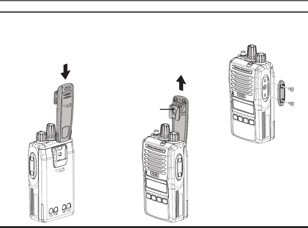
r ToinstalltheBeltClip:alignthe
BeltCliptothegrooveoftheBat-
terypack,thenpresstheBeltClip
downward until it locks in place
witha“Click.”
r To remove the Belt Clip: use a
atheadscrewdrivertopressthe
BeltClipTabawayfromthebat-
terypacktounlocktheBeltClip,
thenslidetheBeltClipupwardto
removeit.
r
MIC/SP
r
MIC/SP
MIC/SP
InstalltheMIC/SPcapwiththesup-
pliedscrews.
Belt Clip Tab
FCC ID: AXI11274620
IC: 10239A-11274620
Vertex Standard LMR, Inc.

VX-264 Operating Manual
9
note
FCC ID: AXI11274620
IC: 10239A-11274620
Vertex Standard LMR, Inc.
10
VX-264 Operating Manual
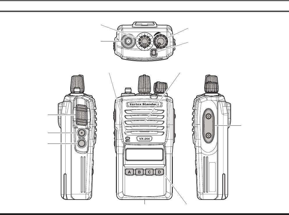
MIC/SPJack
(ExternalMIC/SP)
controls & connectors
4-ButtonProgrammableKey
LEDIndicator(Programmable)
Defaultsettingsare:
SteadyRed: Transmittinginprogress
BlinkingGreen:BusyChannel
SteadyGreen: ToneSquelchindefeatedcondition
PTTSwitch
SIDE-1Button
SIDE-2Button
SpeakerMicrophone
BatteryPackLatch
AntennaJack
CH(Channel)Selector VOL(Volume)/PWR(Power)Knob
FCC ID: AXI11274620
IC: 10239A-11274620
Vertex Standard LMR, Inc.
VX-264 Operating Manual
11
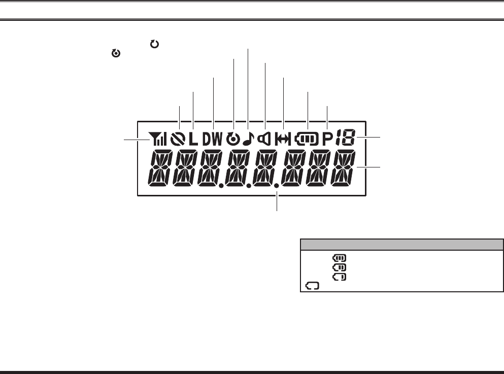
lcd icons & indicators
RSSIIndicator(foursteps)
“Encryption”isactivated
LowTransmitPowerMode“On”
“CALL”Indicator
ReceiverMonitor
BatteryIndicator
GroupNumber
“Dual Watch”isactivated
:“Scan”isenabled
:“Priority Scan”isactivated
“VOX”isactivated
“Talk Around”isenabled
batterY indicator
:
:
:
w/blink:
FullBatteryPower
ModerateBatteryPower
LowBatteryPower
PoorBatteryPower(ChargetheBattery)
PriorityChannelIndicator
8Character
Alpha-NumericDisplay
FCC ID: AXI11274620
IC: 10239A-11274620
Vertex Standard LMR, Inc.
12
VX-264 Operating Manual
oPeration
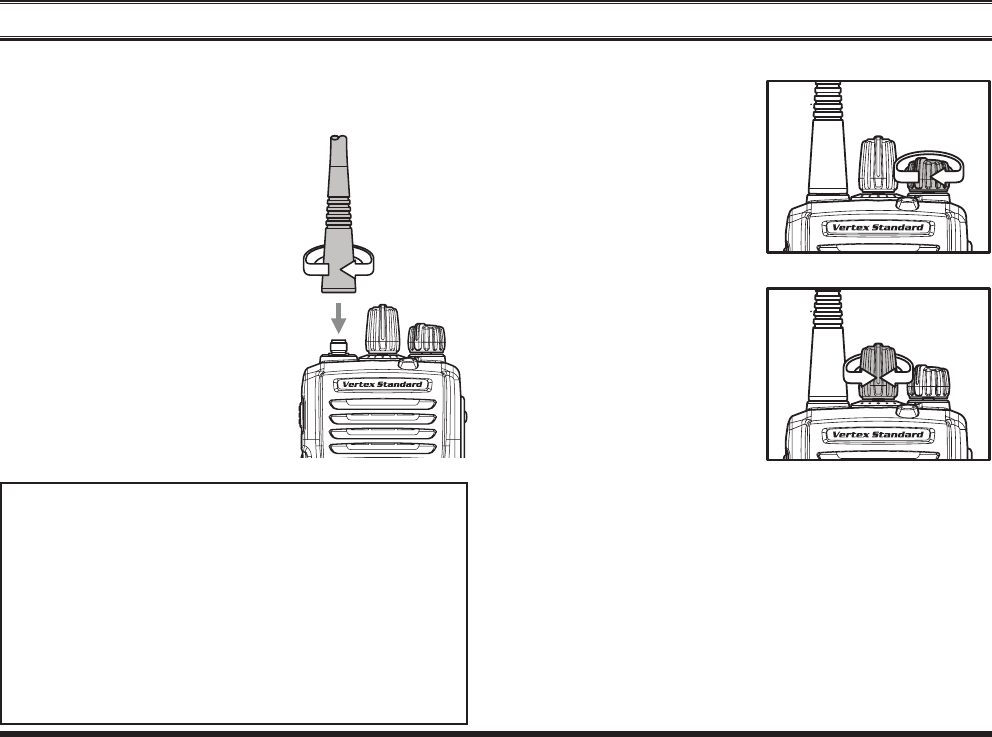
r Installachargedbatterypack ontothe transceiver, as
describedpreviously.
r Screwthesuppliedantenna
ontotheAntennajack.
It is not recommended to oper-
atethistransceiverwithoutan
antennaconnected.
r IfyouhaveaSpeaker/Micro-
phone,werecommendthatit
not be connected until you are
familiarwiththebasicopera-
tion of the VX-264. Refer to
nextpageformoreinformation
aboutSpeaker/Microphoneus-
age.
IMPORTANT NOTE
Waterresistanceofthetransceiver(IP55)isas-
suredonlywhenthefollowingconditions:
r Batterypackisattachedtothetransceiver;
r Antennaisconnectedtotheantennajack;
r
and MIC/SPcapis installedintheMIC/SP
jack.
r Useofaspeakermicrophone intheMIC/SP
jacknegatestheIP55rating.
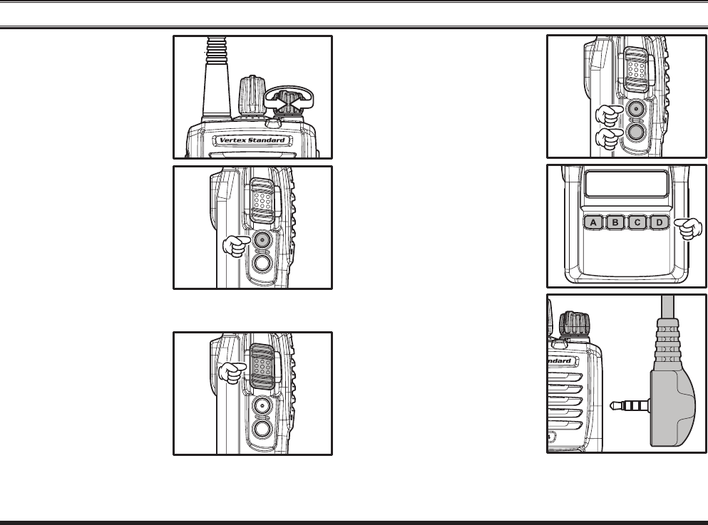
r Tu r n th e t o p p a n e l’s
VOL/PWR knob clock-
wisetoturntheradioon.
r Turn the top panel’s CH Selectorknobto choose the
desiredoperatingchan-
nel.Achannelnamewill
appearontheLCD.
r Ifyouwanttoselecttheoperatingchannelfromadif-
ferentChannelGroup, press(or pressand hold)the
Programmablekeyassignedtothe“grouP uP/doWn”
functionto change desired Channel Group before se-
lectingtheoperatingchannel.
Note:Somemodelsareprogrammedsothattheoper-
atingchannels areselected by theProgrammable key
andtheChannelGroupisselectedbytheCHSelector
knob.Forfurtherdetails,contactyourVertexStandard
dealer.
FCC ID: AXI11274620
IC: 10239A-11274620
Vertex Standard LMR, Inc.
VX-264 Operating Manual
13
oPeration
r Rotate the VOL/PWR
knob to set the volume
level.Ifnosignalispres-
ent on the analog chan-
nel, press (or press and
hold) the Programmable
ke y ( as s ig n e d t o t he
“sql oFF” function:
Normally SIDE-1 but-
ton); background noise
will now be heard, and
you may use this to set
the VOL/PWR knob for
the desired audio level.
Press(orpressandhold)theProgrammablekeyagainto
quietthenoiseandresumenormal(quiet)monitoring.
r To transmit, monitor the
channelandmakesureit
isclear.
Press and hold the PTT
switch.Speakintothe
microphoneareaofthe
front panel grille in a
normalvoicelevel.ToreturntotheReceivemode,re-
leasethePTTswitch.
r Press(orpressandhold)
the ,SIDE-1SIDE-2
button,orfrontpanel’s
programmable keypad
([A] - [D] key) to ac-
tivate one of the pre-
programmedfunctions
whichmayhavebeen
enabled at the time of
pr o g r a m m i n g by t h e
dealer.Seethenext
chapterfordetailsre-
gardingfeatureavailabil-
ityforthisradio.
r IfaSpeaker/Microphone
is available, remove the
plasticcapanditstwo
mountingscrewsfrom
therightsideofthe
transceiver,thenalign
theconnectorofthe
Speaker/Microphoneon
theradio;securethecon-
nectorpinusingthescrewssuppliedwiththeSpeaker/
Microphone. Hold the speaker grille up next to your
earwhilereceiving.Totransmit,pressthePTTswitch
FCC ID: AXI11274620
IC: 10239A-11274620
Vertex Standard LMR, Inc.

14
VX-264 Operating Manual
oPeration
ontheSpeaker/Microphone,justasyouwouldonthe
maintransceiver’sbody,andspeakintothemicro-
phoneonanormalvoicelevel.
Note 1): Save the original plastic cap and its mount-
ing screws. They should be reinstalled when not us-
ing the Speaker/Microphone.
2) When you press the PTT switch on the Speaker/
Microphone, it disables the internal microphone, and
vice versa.
r IftheBCLO(BusyChannelLockout)featurehasbeen
programmedonachannel,theradiowillnottransmit
whenacarrierispresent.Instead,theradiowillgener-
ateshortbeepthreetimes.ReleasethePTTswitchand
waitforthechanneltobeclearofactivity.
r If the BTLO (Busy Tone Lockout) feature has been
programmedonachannel,theradiocantransmitonly
when there is no carrier being received or when the
carrierbeingreceivedincludesthecorrecttone(CTCSS
toneorDCScode).
Iftheselectedchannelhasbeenprogrammedforauto-
matic time-out, you must limit the length of each trans-
mission.Whiletransmitting,abeepwillsound10seconds
before time-out.Another beep will sound just before the
deadline; the top panel’s red LED (“TX” indicator) will
disappearandtransmissionwillceasesoonthereafter.To
resumetransmitting,youmustreleasethePTTswitchand
waitforthe“penaltytimer”toexpire.
FCC ID: AXI11274620
IC: 10239A-11274620
Vertex Standard LMR, Inc.
VX-264 Operating Manual
15
adVanced oPeration
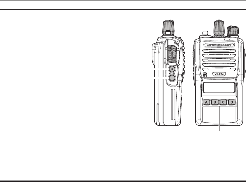
The VX-264 provides sixprogrammablefunction (PF)
keys:SIDE-1,SIDE-2,[A],[B],[C],and[D]keys.
These PF keys can be customized, via programming by
your Vertex Standard dealer, to meet your communica-
tions/networkrequirements.
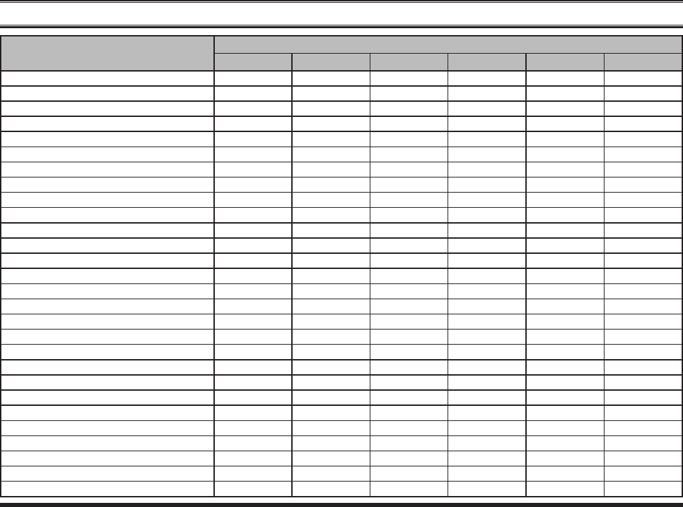
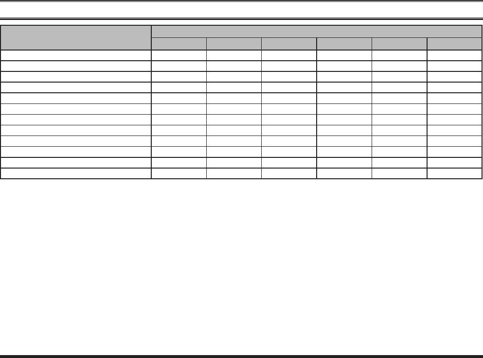
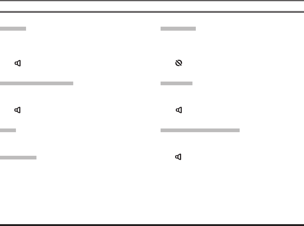
ThepossiblePFkeyprogrammingfeaturesareillustrated
onthenextpage,andtheirfunctionsareexplainedbegin-
ningafterpage18.Forfurtherdetails,contactyourVertex
Standarddealer.
Forfuturereference,checktheboxnexttoeachfunction
that has been assigned to the PF key on your particular
radio,andkeepithandy.
SIDE-1
Button
[A],[B],[C],and[D]Keys
SIDE-2
Button
FCC ID: AXI11274620
IC: 10239A-11274620
Vertex Standard LMR, Inc.
16
VX-264 Operating Manual
adVanced oPeration
Function
Programmable KeY (Press KeY / Press and hold KeY)
SIDE-1 SIDE-2 [A] [B] [C] [D]
None / / / / / /
Monitor / / / / / /
Monitor-Momentarily- /--- /--- /--- /--- /--- /---
Lamp / / / / / /
LowPower / / / / / /
Encryption / / / / / /
SQLOFF / / / / / /
SQLOFF-Momentarily- /--- /--- /--- /--- /--- /---
SQLSet / / / / / /
BeepOFF / / / / / /
Whisper / / / / / /
VOX / / / / / /
VOXSet / / / / / /
Emergency ---/ ---/ ---/ ---/ ---/ ---/
LoneWorker / / / / / /
GroupUp / / / / / /
GroupDown / / / / / /
ChannelUp / / / / / /
ChannelDown / / / / / /
PRI-2 / / / / / /
Scan / / / / / /
GroupScan / / / / / /
DualWatch / / / / / /
Follow-MeScan / / / / / /
ScanSet / / / / / /
GroupScanSet / / / / / /
TA(TalkAround)Scan / / / / / /
TalkAround / / / / / /
FCC ID: AXI11274620
IC: 10239A-11274620
Vertex Standard LMR, Inc.
VX-264 Operating Manual
17
adVanced oPeration
Function
Programmable KeY (Press KeY / Press and hold KeY)
SIDE-1 SIDE-2 [A] [B] [C] [D]
Reset / / / / / /
Call1 / / / / / /
Call2 / / / / / /
Call3 / / / / / /
CodeUp / / / / / /
CodeDown / / / / / /
CodeSet / / / / / /
SpeedDial / / / / / /
Call / / / / / /
Duty / / / / / /
TxSaveDisable / / / / / /
Lock / / / / / /
FCC ID: AXI11274620
IC: 10239A-11274620
Vertex Standard LMR, Inc.
18
VX-264 Operating Manual
adVanced oPeration
encrYPtion
When theVoice Scrambler feature is enabled, press, (or
pressandhold),theassignedPFkeytotoggletheVoice
Encryption“On”and“Off”.
The“ ”iconwillbeindicatedonthedisplaywhenthe
VoiceScramblerisactivated.
sql oFF
Press,(orpressandhold),theassignedPFkeytoopenthe
SQLtohearbackgroundnoise(unmutetheaudio).
The“ ”icon willbe blinkedonthe displaywhenthe
SQLOFFfunctionisactivated.
sql oFF -momentarilY-
OpenstheSQLtohearbackgroundnoise(unmutetheau-
dio)whilepressingtheassignedPFkey.
The“ ”iconwillbeblinkedonthedisplaywhileopen-
ingtheSQL.
monitor
Press,(orpressandhold),theassignedPFkeytocancel
anysignalingfeatures;theLEDindicatorwillglowwitha
pre-denedcolor(Factorydefault:green).
The“ ”iconwillbeindicatedonthedisplay,whenthe
Monitorfunctionisactivated.
monitor -momentarilY-
Cancelanysignalingfeatureswhilepressingtheassigned
PFkey.
The“ ”iconwillbeindicatedonthedisplaywhilecan-
celinganysignalingfeatures.
lamP
Press,(orpressandhold),theassignedPFkeytotoggle
thebacklightofthedisplayandkeypad“On”and“Off”.
loW PoWer
Press,(orpressandhold),theassignedPFkeytosetthe
radio’stransmitterto“LowPower”mode,thusextending
battery life. Press, (or press and hold), the assigned PF
keyagain toreturn to“Normal” transmitpower whenin
difcultterrain.
The “L” icon will be indicated on the display when the
radio’stransmitterissetto“LowPower”mode.
FCC ID: AXI11274620
IC: 10239A-11274620
Vertex Standard LMR, Inc.

VX-264 Operating Manual
19
adVanced oPeration
sql set
Youcanmanuallyadjustthesquelchlevelusingthisfunc-
tion:
r Press,(orpressandhold),theassignedPFkey.Atone
will sound, and the current squelch level will appear
onthedisplay.
r Press the SIDE-1/SIDE-2 buttons (or [A]/[B] keys)
toselectthedesiredsquelchlevel.Availableselections
are“(Open)”,“(Threshold)”,
“(Normal)”and“(Tight)”.
r Pressthe[D]keytostorethenewsetting.Thedisplay
indicates“”briey,thenrevertstothenormal
channelindication.
You may cancel the new setting by pressing the [C]
key.Inthiscase,thedisplayindicates“”
briey.
beeP oFF
Press,(orpressandhold),theassignedPF key to dis-
able the radio beeps temporarily. Press again, (or press
andholdagain),theassignedPFkeytoenabletheradio
beeps.
WhentheBeepOfffunctionis“on”and“off”,thedisplay
indicatesbriey“”and“”.
WhisPer
Press,(orpressandhold),theassignedPFkeytoincrease
the microphone gain; thus you can speak in a low voice
(whisper)temporarily.Pressagain,(orpressandhold
again),theassignedPFkeytoresumenormalmicrophone
gain.
WhentheWhisperfunctionis“on”and“off”,thedisplay
indicates“”and“”briey.
Vox
Press, (or press and hold), the assigned PF key to acti-
vate the VOX function; allowing hands-free, automatic
activationofthetransmitter,basedonvoiceinputintothe
microphone.YoumaydisabletheVOXfunctiontempo-
rarilybypressingthePTTswitch.
Press again, (or press and hold again), the assigned PF
keytoresumenormaloperation.
Note 1:whentheVOXfunctionisactivatedbyoperation
fromtheexternalequipment,asmalldot(“”)willbein-
dicatedatthebottomrightofthedisplay.
Note 2:whentheVOXfunctionis“on”and“off”,thedis-
playindicates“”and“”briey.
FCC ID: AXI11274620
IC: 10239A-11274620
Vertex Standard LMR, Inc.
20
VX-264 Operating Manual
adVanced oPeration
Vox set
YoucanmanuallyadjusttheVOXGainusingthisfunction:
r Press,(orpressandhold),theassignedPFkey.Atone
will sound, and the current VOX Gain level will ap-
pearonthedisplay.
r Press the [A]/[B] button to select the desired VOX
Gainlevel.
r Pressthe[D]keytostorethenewsetting.Thedisplay
indicates“”briey,thenrevertstothenormal
channelindication.
You may cancel the new setting by pressing the [C]
key.Inthiscase,thedisplayindicates“”
briey.
emergencY
The VX-264 includes an “Emergency” feature in either
analogordigitalmodes,whichmaybeusefulforalerting
another party monitoring on the same frequency as your
transceiver’schannel.
PressandholdtheassignedPFkeyforapre-programmed
periodtoinitiateanemergencycallonthepre-defined
channel. The “ ” indication will be indicated on
the display. For further details contact your Vertex Stan-
darddealer.
TorevivetheradiofromtheEmergencymode,justpress
andholdagaintheassignedPFkeyorturnofftheradio.
lone WorKer
Press,(orpressandhold),theassignedPFkeytoactivate
theLoneWorkerfeature.The LoneWorkerfeatureis
designedtoemitanalarmfor30secondswhentheLone
Worker Timer (programmed by your Vertex Standard
dealer)hasexpired.
Press again, (or press and hold again), the assigned PF
key,theLoneWorkerfeatureisdisabled.Iftheuserdoes
notresetthetimerbypressingthePTTswitch,theradio
switchestoEmergencymode.
Note:whentheLoneWorkerfeatureis“on”and“off”,the
displayindicates“”and“”briey.
grouP uP/doWn
Press,(orpressandhold),theassignedPFkeytoselecta
differentgroupof channels.Agroup numberwill appear
at the upper right corner and a group name will appear
brieyonthedisplay.
channel uP/doWn
Press,(orpressandhold),theassignedPFkeytoselecta
differentchannel.A channel namewill appear briey on
thedisplay.
FCC ID: AXI11274620
IC: 10239A-11274620
Vertex Standard LMR, Inc.

VX-264 Operating Manual
21
Pri-2
Press,(or press and hold), the assigned PF key to recall
thepre-programmedPriorityChannelofthecurrentgroup
(Priority-2)byyourVertexStandarddealerdirectly.When
PRI-2channelisrecalled,the“P”iconwillappearonthe
display.
scan
The Scanning feature is used to monitor multiple chan-
nelsprogrammedintothetransceiver.Whilescanning,the
transceiverwillcheckeachchannelforthepresenceofa
signal,andwillstoponachannelifasignalispresent.
To activate scanning:
r Press,(orpressandhold),theassignedPFkeytoacti-
vatescanning.
r Thescannerwillsearchthechannelsofeachchannel,
lookingforactiveones;itwillpauseeachtimeitnds
achannelonwhichsomeoneisspeaking.
r Pressagain,(orpressandholdagain),theassignedPF
keytodisablescanning,andreceivethechannelwhich
waschosenwhenpressedthePFkey.
Note:Your dealer may have programmed your radio to
stayononeofthefollowingchannelsifyoupressthe
PTTswitchduringscanningpause:
“ScanPause”channel(“TalkBack”)
“LastBusy”channel
“Priority-1”channel
“Priority-2”channel
“UserProgrammed”channel(“SelectChannel”)
ThechannelwhichdefinedintheCHSelector
knob.
grouP scan
The scanning feature is used to monitor multiple chan-
nelsprogrammedintothetransceiver.Whilescanning,the
transceiver will check each channel of the programmed
group for the presence of the signal, and will stop on a
channelifasignalispresent.
Press,(orpressandhold),theassignedPFkeytoactivate
thescanningontheselectedgroups.
Press again, (or press and hold again), the assigned PF
keytodisablethegroupscanmode,andreceivethechan-
nelwhichwaschosenwhenpressedthePFkey.
When the Group Scan is activated, the display indicates
“”briey.
adVanced oPeration
FCC ID: AXI11274620
IC: 10239A-11274620
Vertex Standard LMR, Inc.
22
VX-264 Operating Manual
adVanced oPeration
dual Watch
The Dual Watch feature is similar to the SCAN feature,
exceptthatonlytwochannelsaremonitored:
Thecurrentoperatingchannel;and
ThePriority-2channel.
To activate Dual Watch:
r Press,(orpressandhold),theassignedPFkeytoacti-
vatetheDualWatchfeature.
r Thescannerwillsearchthetwochannels;itwillpause
eachtimeitfindsachannelonwhichsomeoneis
speaking.
When the Dual Watch feature is activated, the
“ ”iconwillbeindicatedonthedisplay.
To stop Dual Watch:
r Press,(orpressandhold),theassignedPFkeytodis-
abletheDualWatchfeature.
r Theradioreceivesthechannelwhichwaschosen
whenpressedthePFkey.
FolloW me scan
TheFollowMeScanfeaturechecksauser-assignedprior-
itychannelregularlyasyouscanotherchannels.Thus,if
onlyChannels1,3,and5(ofthe8availablechannels)are
designated for “Scanning”, the user may nonetheless as-
signChannel2asthe“user-assigned”prioritychannelvia
theFollowMeScan.
ToactivateFollowMe Scan, rstselectthe channel you
wanttodesignateas the“user-assignedprioritychannel”
and press, (or press and hold), the assigned PF key (the
display indicates “” briefly).Then rotate the
CHSelectorknobtorecalltothe“ScanningStart”chan-
nelwhichhasbeenprogrammedbyyourdealertoactivate
thescanner.Whenthescannerstopsonan“Active”chan-
nel,the user-assignedpriority channel will automatically
becheckedeveryfewseconds;ifactivityisfoundonthe
user-assigned priority channel, the radio will switch be-
tweenitandthedealer-assignedprioritychannel,ifany.
FCC ID: AXI11274620
IC: 10239A-11274620
Vertex Standard LMR, Inc.
VX-264 Operating Manual
23
adVanced oPeration
scan set
Press,(orpressandhold),theassignedPFkeytoadd/de-
letethecurrentchannelto/fromyourscanninglist.
Tostoreaparticularchanneltoyourscanninglist,press,(or
pressandhold),theassignedPFkey.Ifyoudeleteachan-
nelfromyourscanninglist,press,(orpressandhold),the
assignedPFkeyagain.
Whenthescannerispaused,youmayremovethechannel
from the scan list temporarily by pressing, (or press and
holding),thesamekey.
Note 1:whenstoreaparticularchanneltoyourscanning
list,thedisplayindicates“”brieyand“ ”icon
willappearonthedisplay.
Note 2:whendeleteachannelfromyourscanninglist,the
display indicates “ ” briey and the “ ” icon
willdisappearfromthedisplay.
grouP scan set
YoumaywishtohavetheScannerpassthroughmorethan
one Group during the scanning process (normally, scan-
ningisperformedwithinthecurrentgrouponly).
ToincludethecurrentGroupinthescanningloop,press,
(orpressandhold),theassignedPFkey.Toremoveacur-
rentGroup from Group Scan, press, (or press and hold),
theassignedPFkeyagain.
ta (talK around) scan
Press,(orpressandhold),theassignedPFkeytotoggle
theTAScanfeature“On”and“Off”.
WhileTAScanisproceeding,thetransceiver willsearch
boththetransmitandreceivefrequencies.Whenasignal
is encountered on the receive frequency, the transceiver
will pause until the signal disappears. When a signal is
encounteredonthetransmitfrequency,thetransceiver
willcheckforactivityonthereceivefrequencyeveryfew
seconds (interval programmed by your Vertex Standard
dealer).
WhentheTAScanfeatureisactivated,the“ ”iconwill
beblinkedonthedisplay.
Note:TheTAScanfeaturedoesnotactivateontheSim-
plexChannel.
FCC ID: AXI11274620
IC: 10239A-11274620
Vertex Standard LMR, Inc.
24
VX-264 Operating Manual
talK around
Press,(orpressandhold),theassignedPFkeytoactivate
theTalkAroundfeaturewhenyouareoperatingonduplex
channel systems (separate receive and transmit frequen-
cies,utilizinga“repeater”station).TheTalkAround
featureallowsyoutobypasstherepeaterstationandtalk
directlytoastationthatisnearby.Thisfeaturehasnoef-
fectwhenyouareoperatingon“simplex”channels,where
thereceiveandtransmitfrequenciesarealreadythesame.
WhentheTalkAroundfeatureisactivated,the“ ”icon
willbeindicatedonthedisplay.
Notethatyourdealermayhavemodeprovisionfor“Talk
Around” channels by programming “repeater” and “Talk
Around”frequenciesontwoadjacentchannels.Ifso,the
keymaybeusedfor oneoftheotherPre-Programmed
Functions.
Note:The TalkAround feature does not activate on the
SimplexChannel.
reset
Press(orpressandhold)theassignedPFkeytoresetthe
RFC(ReadyforCommunication)condition.
call 1 to call 3
Press,(orpressandhold),theassignedPFkeytosenda
pre-programmedcallsignalofthe5-Tone.
code uP/doWn
Press,(orpressandhold),theassignedPFkeytoselecta
2-Toneor5-Toneencodecodefromthepre-programmed
encodelist.
code set
Youcanchangethe desireddigitof the5-Toneencode
codeusingthisfunction:
r Press,(orpressandhold),theassignedPFkey.
r Enterthedesired5-Toneencode codedirectlyfrom
the[A]/[B]keys(selectthecodenumber)andSIDE-
1/SIDE-2buttons(selectthecodedigit).
r Pressthe[D]keytostorethenewsetting.Thedisplay
indicates“”briey,thenrevertstothenormal
channelindication.
You may cancel the new setting by pressing the [C]
key.Inthiscase,thedisplayindicates“”
briey.
adVanced oPeration
FCC ID: AXI11274620
IC: 10239A-11274620
Vertex Standard LMR, Inc.
VX-264 Operating Manual
25
sPeed dial
Your Vertex Standard dealer may have pre-programmed
Auto-Dialtelephonenumbermemoriesintoyourradio.
Todialanumber:
Press,(orpressandhold),theassignedPFkey,thenpress
the SIDE-1/SIDE-2 buttons (or [A]/[B] keys) to select
theAuto-Dialmemorynumberyouwishtodial.Pressthe
PTTswitchtosendapre-denedDTMFtone.TheDTMF
tonessentduringthedialingsequencewillbeheardinthe
speaker.
call
Press,(orpressandhold),theassignedPFkeytosenda
pre-programmed 2-Tone encode code or MDC1200® en-
codecode(ANIencodecode).
adVanced oPeration
dutY
Press,(orpressandhold),theassignedPFkeytotoggle
theDutyfunctionofthe2-Toneor5-Tone“On”and“Off”.
Whenthe Dutyfunction isset to “On”,the displayindi-
cates “ ” briefly and the user will always hear
(depending on the sub-audio signaling) all trafc on the
pagingchannel.Theradiowillsoundthepagingalert
whenitreceivestheprogrammed2-Toneor5-Tone.
Whenthe Dutyfunction isset to“Off”,thedisplay in-
dicates “ ” briey and the user will NOT hear
normalradiotrafconthepagingchannel.Theradiowill
soundthepagingalertandunmuteonlywhenitreceives
theprogrammed2-Toneor5-Tone.
FCC ID: AXI11274620
IC: 10239A-11274620
Vertex Standard LMR, Inc.

26
VX-264 Operating Manual
tx saVe disable
The Transmit Battery Saver helps extend battery life by
reducingtransmit power when a very strong signal from
anapparentlynearbystationisbeingreceived.Under
some circumstances, though, your hand-held radio may
notbeheard wellat theother endof thecommunication
path,andhighpowermaybenecessaryatalltimes.
Press,(orpressandhold),theassignedPFkeytodisable
theTransmitBatterySaver,ifyouareoperatinginaloca-
tionwherehighpowerisalmostalwaysneeded.
Press again, (or press and hold again), the assigned PF
key, the Transmit Battery Saver activates to reduce the
transmitpowerwhenaverystrongsignalfromanappar-
entlynearbystationisbeingreceived.
When theTransmit Battery Saver is “on” and “off”, the
displayindicates“”and“”briey.
locK
Press(orpressandhold)theassignedPFkeytolockthe
CHSelectorknob,Programmablekeys,andPTTswitch.
locK
Inordertopreventaccidentalchannelchangeorinad-
vertenttransmission,variousaspectsoftheCH Selec-
tor knob, Programmable keys, and PTT switch may be
locked.Thepreciselockoutcongurationisprogrammed
byyourDealer.
To locked out the key locking, turn the radio off. Now,
pressandholdthePTTandSIDE-2keywhileturningthe
radioonagain.
Tocancellocking,repeatthisprocess.
arts™
(auto range transPond sYstem)
Thissystemisdesignedtoinformyouwhenyouandan-
otherARTS™-equippedstationarewithincommunication
range.
DuringARTS™operation,whentheradioreceivesan
incomingARTS™signal,ashortbeepwillsoundand“
”(“InService”)willbeindicatedonthedisplay
for2seconds.Ifyoumoveoutof rangeformorethan
twominutes,yourradiosensesthatnosignalhasbeenre-
ceived;ashorttriple-beepwillsoundand“”
(“Outof Service”) willbe indicated onthe display for2
seconds.Ifyousubsequentlymovebackintocommunica-
tionrange,as soonas theother stationtransmits, ashort
beepwillsoundagainand“”(“InService”)will
beindicatedagainonthedisplayfor2seconds.
adVanced oPeration
FCC ID: AXI11274620
IC: 10239A-11274620
Vertex Standard LMR, Inc.
VX-264 Operating Manual
27
oPtional accessories
FNB-V133LI-UNI 7.4V ,1380mAhLi-IonBatteryPack
FNB-V134LI-UNI 7.4V ,2300mAhLi-IonBatteryPack
CD-58 DesktopCharger
PA-55ACAdapterforCD-58
VAC-UNI DesktopCharger(CD-58+PA-55)
VAC-6058 Multi-UnitCharger
MH-360S CompactSpeakerMicrophone
MH-450S SpeakerMicrophone
MH-66A4B SubmersibleSpeakerMicrophone
MH-37A4B-1 EarpieceMicrophone
MH-81A4B Over-the-headVOXCompatibleHeadset
VCM-5 VehicularChargerMountingAdapterforCD-58
ATV-8A VHFAntenna(134-151MHz)
ATV-8B VHFAntenna(150-162MHz)
ATV-8C VHFAntenna(161-174MHz)
ATV-6XL VHFAntenna(Untuned)
ATU-6A UHFAntenna(400-430MHz)
ATU-6B UHFAntenna(420-450MHz)
ATU-6C UHFAntenna(440-470MHz)
ATU-6D UHFAntenna(450-485MHz)
ATU-6F UHFAntenna(485-520MHz)
CN-3 AntennaAdapter
CLIP-20 BeltClip
CE150 PCProgrammingSoftware
FIF-12 USBProgrammingInterface
CT-106 ConnectionCableforFIF-12
CT-27 RadiotoRadioCloningCable
Availability of accessories may vary; some ac-
cessories are supplied standard per local re-
quirements, others may be unavailable in some
regions. Check with your Vertex Standard Dealer
for changes to this list.
FCC ID: AXI11274620
IC: 10239A-11274620
Vertex Standard LMR, Inc.

28 VX-264 Operating Manual
WarrantY PolicY
Vertex Standard warrants, to the original purchaser only, its Vertex Standard manufactured communications products
againstdefectsinmaterialsandworkmanshipundernormaluseandserviceforagivenperiodoftimefromthedateofpur-
chase.
LimitedWarrantyDetails:
NorthAmericacustomers(USAandCanada):http://www.vertexstandard.com/lmr/warranty-terms.aspx
CustomersoutsideofNorthAmerica:contacttheauthorizeddealerinyourcountry.
FCC ID: AXI11274620
IC: 10239A-11274620
Vertex Standard LMR, Inc.
Part15.21:ChangesormodicationstothisdevicenotexpresslyapprovedbyVertexStandardcouldvoidtheuser’s
authorizationtooperatethisdevice.
TheAMBE+2™voicecodingTechnologyembodiedinthisproductisprotectedbyintellectualpropertyrightsin-
cludingpatentrights,copyrightsandtradesecretsofDigitalVoiceSystems, Inc.ThisvoicecodingTechnologyis
licensedsolelyforusewithinthisCommunicationsEquipment.TheuserofthisTechnologyisexplicitlyprohibited
fromattemptingto decompile,reverseengineer,or disassembletheObject Code,or inanyother wayconvertthe
ObjectCodeintoahuman-readableform.
U.S. Pat. Nos. #5,870,405, #5,826,222, #5,754,974, #5,701,390, #5,715,365, #5,649,050, #5,630,011, #5,581,656,
#5,517,511,#5,491,772,#5,247,579,#5,226,084and#5,195,166.
Productswiththesymbol(crossed-outwheeledbin)cannotbedisposedashouseholdwaste.
Electronic and Electric Equipment should be recycled at a facility capable of handling these items and
theirwastebyproducts.
InEUcountries,pleasecontactyourlocalequipmentsupplierrepresentativeorservicecenterforinforma-
tionaboutthewastecollectionsysteminyourcountry.
FCC ID: AXI11274620
IC: 10239A-11274620
Vertex Standard LMR, Inc.

Copyright2014
VertexStandardLMR,Inc.
Allrightsreserved.
Noportionofthismanual
maybereproduced
withoutthepermissionof
VertexStandardLMR,Inc.
Vertex Standard LMR, Inc.
FCC ID: AXI11274620
IC: 10239A-11274620
Vertex Standard LMR, Inc.