Vertex Standard USA 11374720 Handheld Portable UHF Non-Display fixed antenna User Manual EVX 261 OM ENG EC137U102 FCC 160817 indd
Vertex Standard USA, Inc. Handheld Portable UHF Non-Display fixed antenna EVX 261 OM ENG EC137U102 FCC 160817 indd
User Manual
PROGRAMMABLE FUNCTIONS/FEATURES
IP55 Water Resistant
Two Programmable Function Keys
2-Tone Encode/Decode
5-Tone Encode/Decode
MDC-1200® Encode (ANI Encode)
DTMF Encode
Scan
Dual Watch
Follow-Me Scan
Talk Around Scan
Encryption
VOX
Talk Around
Emergency
Selective Call
(2-Tone/5-Tone/Digital)
Remote Control Decoder (Digital only)
Transmit Battery Saver
ARTS™ (Auto Range Transpond System)
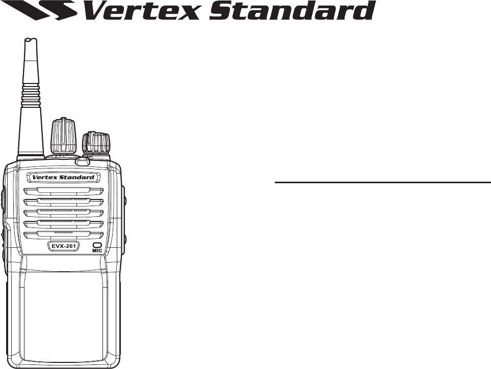
EVX-261
EVX-261
OPERATING MANUAL
OPERATING MANUAL
Exhibit 8: Operating Manual
FCC ID: AXI11374720
IC: 10239A-11374720
Vertex Standard LMR, Inc.

Introduction .....................................................................1
Class B Digital Device .....................................................2
Warning! FCC RF Exposure Requirements .................3
Warning! IC RSS General Requirement ......................5
Before You Begin .............................................................7
Battery Pack Installation and Removal ....................... 7
Battery Charging .........................................................7
Low Battery Indication ................................................8
Belt Clip Installation and Removal ............................. 9
MIC/SP Cap Installation .............................................9
Controls & Connectors .................................................10
Operation ....................................................................... 11
Preliminary Steps ...................................................... 11
Operation Quick Start ................................................ 11
Digital Mode Specifi c Features .................................13
Automatic Time-Out Timer ....................................... 14
Advanced Operation .....................................................15
Programmable Key Functions ..................................15
Description of Operating Functions ......................... 16
Lock ................................................................................20
ARTS™ (Auto Range Transpond System) .................20
Optional Accessories .....................................................21
CONTENTS
Congratulations!
You now have at your fi ngertips a valuable communications tool, a Vertex Standard two-way radio! Rugged, reliable and
easy to use, your Vertex Standard radio will keep you in constant touch with your colleagues for years to come, with negli-
gible maintenance down-time. Please take a few minutes to read this manual carefully. The information presented here will
allow you to derive maximum performance from your radio, in case questions arise later on.
Important Note
There are no owner-serviceable parts inside the radio. All service jobs must be referred to an authorized Vertex
Standard Service Representative.
In order to maintain the specifi ed water integrity performance, periodic maintenance is recommended.
Should the radio sustain a severe shock (e.g. if it is dropped), the water integrity may be compromised, requiring
service. Should this occur, contact your Authorized Vertex Standard Dealer.
Exhibit 8: Operating Manual
FCC ID: AXI11374720
IC: 10239A-11374720
Vertex Standard LMR, Inc.

EVX-261 OPERATING MANUAL 1
Important Notice for North American Users Regarding 406 MHz Guard Band
The U.S. Coast Guard and National Oceanographic and Atmospheric Administration have requested the cooperation
of the U.S. Federal Communications Commission in preserving the integrity of the protected frequency range 406.0
to 406.1 MHz, which is reserved for use by distress beacons. Do not attempt to program this apparatus, under any
circumstances, for operation in the frequency range 406.0 - 406.1 MHz if the apparatus is to be used in or near North
America.
Warning - Frequency band 406 - 406.1 MHz is reserved for use ONLY as a distress beacon by the US Coast Guard
and NOAA. Under no circumstance should this frequency band be part of the pre programmed operating frequencies
of this radio.
INTRODUCTION
The EVX-261 is full-featured Hand-Held Digital/Analog Transceiver designed for business communications in the VHF/
UHF Land Mobile bands. The EVX-261 supports up to 16 user confi gurable channels supporting a wide variety of business
applications.
Channel frequency data for the transceiver is stored in fl ash memory, which is easily programmed by Vertex Standard li-
censed dealers using a standard PC and the following Vertex Standard programming equipment:
1) FIF-12 USB programming interface
2) CT-106 radio programming cable
3) CE156 PC programming Software
Additional radio to radio programming can be achieved with a CT-27 Cloning cable.
This manual will describe in detail the many advanced features of the EVX-261. After reading this manual, you may wish
to consult with your Network Administrator regarding precise details of the confi guration of this equipment for use in your
application.
Exhibit 8: Operating Manual
FCC ID: AXI11374720
IC: 10239A-11374720
Vertex Standard LMR, Inc.

2 EVX-261 OPERATING MANUAL
CLASS B DIGITAL DEVICE
NOTE: This equipment has been tested and found to comply with the limits for a Class B digital device, pursuant to part 15
of the FCC Rules. These limits are designed to provide reasonable protection against harmful interference in a residential
installation. This equipment generates uses and can radiate radio frequency energy and, if not installed and used in accor-
dance with the instructions, may cause harmful interference to radio communications. However, there is no guarantee that
interference will not occur in a particular installation. If this equipment does cause harmful interference to radio or televi-
sion reception, which can be determined by turning the equipment off and on, the user is encouraged to try to correct the
interference by one or more of the following measures:
Reorient or relocate the receiving antenna.
Increase the separation between the equipment and receiver.
Connect the equipment into an outlet on a circuit different from that to which the receiver is connected.
Consult the dealer or an experienced radio/TV technician for help.
Exhibit 8: Operating Manual
FCC ID: AXI11374720
IC: 10239A-11374720
Vertex Standard LMR, Inc.
EVX-261 OPERATING MANUAL 3
WARNING! FCC RF EXPOSURE REQUIREMENTS
THIS DEVICE COMPLIES WITH PART 15 OF THE FCC RULES. OPERATION IS SUBJECT TO THE FOLLOWING TWO CON-
DITIONS: (1) THIS DEVICE MAY NOT CAUSE HARMFUL INTERFERENCE, AND (2) THIS DEVICE MUST ACCEPT ANY IN-
TERFERENCE RECEIVED, INCLUDING INTERFERENCE THAT MAY CAUSE UNDESIRED OPERATION.
This Radio has been tested and complies with the Federal Communications Commission (FCC) RF exposure limits for Oc-
cupational Use/Controlled exposure environment. In addition, it complies with the following Standards and Guidelines:
FCC 96-326, Guidelines for Evaluating the Environmental Effects of Radio-Frequency Radiation.
FCC OET Bulletin 65 Edition 97-01 (2001) Supplement C, Evaluating Compliance with FCC Guidelines for Human
Exposure to Radio Frequency Electromagnetic Fields.
ANSI/IEEE C95.1-1992, IEEE Standard for Safety Levels with Respect to Human Exposure to Radio Frequency Elec-
tromagnetic Fields, 3 kHz to 300 GHz.
ANSI/IEEE C95.3-1992, IEEE Recommended Practice for the Measurement of Potentially Hazardous Electromagnetic
Fields - RF and Microwave.
WARNING:
This radio generates RF electromagnetic energy during transmit mode. This radio is designed for and classifi ed as
Occupational Use Only, meaning it must be used only during the course of employment by individuals aware of the
hazards, and the ways to minimize such hazards. This radio is not intended for use by the General Population in an
uncontrolled environment.
CAUTION:
To ensure that your expose to RF electromagnetic energy is within the FCC allowable limits for occupational use,
always adhere to the following guidelines:
This radio is NOT approved for use by the general population in an uncontrolled exposure environment. This ra-
dio is restricted to occupational use, work related operations only where the radio operator must have the knowl-
edge to control his or her RF exposure conditions.
Exhibit 8: Operating Manual
FCC ID: AXI11374720
IC: 10239A-11374720
Vertex Standard LMR, Inc.

4 EVX-261 OPERATING MANUAL
WARNING! FCC RF EXPOSURE REQUIREMENTS
When transmitting, hold the radio in a vertical position with its microphone 1 inch (2.5 cm) away from your
mouth and keep the antenna at least 1 inch (2.5 cm) away from your head.
Transmit no more than the rated duty factor of 50% of the time. To transmit (talk), push the Push-To-Talk (PTT)
button. To receive calls, release the PTT button. The PTT button may reside on the radio itself or may be hosted
on approved accessories. Transmitting 50% of the time, or less, is important because this radio generates mea-
surable RF energy exposure only when transmitting (in terms of measuring for standards compliance).
The radio is transmitting when the red LED on the top of the radio is illuminated.
In front of the face. Hold the radio in a vertical position with the microphone (and other parts of the radio in-
cluding the antenna) at least 1 inch (2.5 cm) away from the nose or lips. Keeping the radio at a proper distance is
important to ensure compliance.
Body Worn Operation: When worn on the body, always place the radio in a Vertex Standard approved clip, hold-
er, holster, case, or body harness for this product. Using approved body-worn accessories is important because
the use of non-Vertex Standard approved accessories may result in exposure levels, which exceed the occupation-
al/controlled environment RF exposure limits.
Always use Vertex Standard authorized accessories.
The information listed above provides the user with the information needed to make him or her aware of RF ex-
posure, and what to do to assure that this radio operates with the FCC RF exposure limits of this radio.
Electromagnetic Interference/Compatibility
During transmissions, this radio generates RF energy that can possibly cause interference with other devices or
systems. To avoid such interference, turn off the radio in areas where signs are posted to do so.
Do not operate the transmitter in areas that are sensitive to electromagnetic radiation such as hospitals, health
care facilities, aircraft, and blasting sites.
Exhibit 8: Operating Manual
FCC ID: AXI11374720
IC: 10239A-11374720
Vertex Standard LMR, Inc.
EVX-261 OPERATING MANUAL 5
WARNING! IC RSS GENERAL REQUIREMENT
ENGLISH
This device complies with Industry Canada’s license-exempt RSSs. Operation. Operation is subject to the following two
conditions:
(1) This device may not cause interference; and
(2) This device must accept any interference, including interference that may cause undesired operation of the device.
Under Industry Canada regulations, this radio transmitter may only operate using an antenna of a type and maximum (or
lesser) gain approved for the transmitter by Industry Canada. To reduce potential radio interference to other users, the
antenna type and its gain should be so chosen that the equivalent isotropically radiated power (e.i.r.p.) is not more than
that necessary for successful communication.
This radio transmitter (identify the device by certification number, or
model number if Category II) has been approved by Industry Canada to
operate with the antenna types listed at the right with the maximum per-
missible gain and required antenna impedance for each antenna type in-
dicated. Antenna types not included in this list, having a gain greater than
the maximum gain indicated for that type, are strictly prohibited for use
with this device.
When transmitting, hold the radio in a vertical position with its microphone 1 inch (2.5 cm) away from your
mouth and keep the antenna at least 1 inch (2.5 cm) away from your head.
The radio must be used with a maximum operating duty cycle not exceeding 50%, in typical Push-to-Talk con-
fi gurations.
DO NOT transmit for more than 50% of total radio use time (50% duty cycle). Transmitting more than 50% of
the time can cause IC RSS General Requirement to be exceeded. The radio is transmitting when the red LED on
the top of the radio is illuminated.
Body Worn Operation: When worn on the body, always place the radio in a Vertex Standard approved clip, hold-
er, holster, case, or body harness for this product. Using approved body-worn accessories is important because
the use of non-Vertex Standard approved accessories may result in exposure levels, which exceed the occupation-
al/controlled environment RF exposure limits.
VHF MODEL UHF MODEL
ATV-8A: −2.15 dBi, 50-ohm ATU-6A: −2.15 dBi, 50-ohm
ATV-8B: −2.15 dBi, 50-ohm ATU-6B: −2.15 dBi, 50-ohm
ATV-8C: −2.15 dBi, 50-ohm ATU-6C: −2.15 dBi, 50-ohm
ATV-6XL: −2.15 dBi, 50-ohm ATU-6D: −2.15 dBi, 50-ohm
ATU-6F: −2.15 dBi, 50-ohm
ATU-6DS: −2.15 dBi, 50-ohm
Exhibit 8: Operating Manual
FCC ID: AXI11374720
IC: 10239A-11374720
Vertex Standard LMR, Inc.
6 EVX-261 OPERATING MANUAL
FRENCH
Le présent appareil est conforme aux CNR d’Industrie Canada applicables aux appareils radio exempts de licence. L’ex-
ploitation est autorisée aux deux conditions suivantes :
(1) l’appareil ne doit pas produire de brouillage, et
(2) l’utilisateur de l’appareil doit accepter tout brouillage radioélectrique subi, même si le brouillage est susceptible d’en
compromettre le fonctionnement.
Conformément à la réglementation d’Industrie Canada, le présent émetteur radio peut fonctionner avec une antenne
d’un type et d’un gain maximal (ou inférieur) approuvé pour l’émetteur par Industrie Canada. Dans le but de réduire les
risques de brouillage radioélectrique à l’intention des autres utilisateurs, il faut choisir le type d’antenne et son gain de
sorte que la puissance isotrope rayonnée quivalente (p.i.r.e.) ne dépassepas l’intensité nécessaire à l’établissement d’une
communication satisfaisante.
Le présent émetteur radio (identifi er le dispositif par son numéro de certi-
fi cation ou son numéro de modèle s’il fait partie du matériel de catégorie
I) a été approuvé par Industrie Canada pour fonctionner avec les types
d’antenne énumérés dans le droit et ayant un gain admissible maximal et
l’impédance requise pour chaque type d’antenne. Les types d’antenne non
inclus dans cette liste, ou dont le gain est supérieur au gain maximal indi-
qué, sont strictement interdits pour l’exploitation de l’émetteur.
Pour émettre, tenez votre radio verticalement en plaçant le microphone entre 2,5 cm de la bouche. L’antenne doit
toujours être à plus de 2,5 cm de votre tête.
Le temps total d’émission de la radio ne doit pas dépasser 50% du temps de fonctionnement dans une confi guration
normale avec alternat.
Par conséquent, vous ne devez PAS émettre pendant plus de 50% du temps total d’utilisation de la radio. La radio
émet lorsque le voyant LED rouge (situé au sommet de la radio) est allumé.
Utilisation lorsque la radio est portée sur soi: Lorsque la radio est portée sur soi, utilisez toujours une pince ou
une attache de ceinture, placez-la dans un étui ou dans un harnais pour le corps approuvé par Vertex Standard
pour ce produit. Il est important d’utiliser des accessoires ajustés au corps qui sont approuvés, car dans le cas
contraire, l’utilisateur risque de s’exposer à des niveaux d’énergie de RF supérieurs aux limites établies pour les
environnements professionnels ou à exposition contrôlée.
WARNING! IC RSS GENERAL REQUIREMENT
VHF MODÈLE UHF MODÈLE
ATV-8A: −2.15 dBi, 50-ohm ATU-6A: −2.15 dBi, 50-ohm
ATV-8B: −2.15 dBi, 50-ohm ATU-6B: −2.15 dBi, 50-ohm
ATV-8C: −2.15 dBi, 50-ohm ATU-6C: −2.15 dBi, 50-ohm
ATV-6XL: −2.15 dBi, 50-ohm ATU-6D: −2.15 dBi, 50-ohm
ATU-6F: −2.15 dBi, 50-ohm
ATU-6DS: −2.15 dBi, 50-ohm
Exhibit 8: Operating Manual
FCC ID: AXI11374720
IC: 10239A-11374720
Vertex Standard LMR, Inc.
EVX-261 OPERATING MANUAL 7
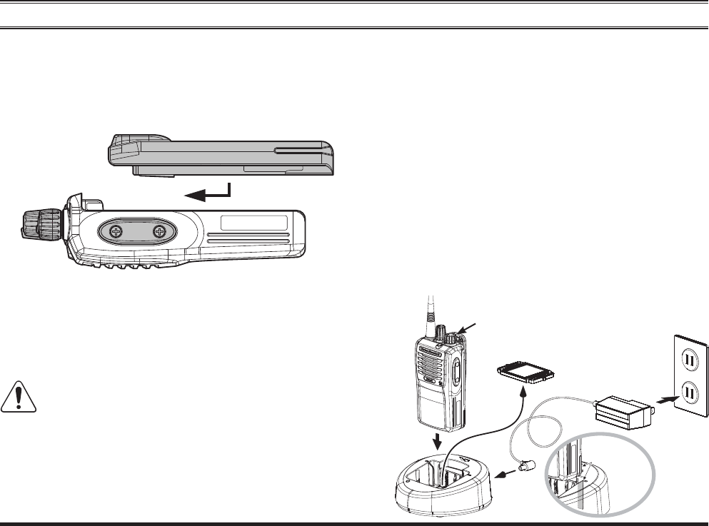
BEFORE YOU BEGIN
To remove the battery, turn the radio off and remove
any protective cases. Slide the Battery Pack Latch on
the bottom of the radio toward the front panel while
sliding the battery down about 1/2 inch (1.5 cm). Then
lift the battery out from the radio.
Do not attempt to open any of the rechargeable
Lithium-Ion packs, as they could explode if ac-
cidentally short-circuited.
Battery Pack Installation and Removal
To install the battery pack, align the battery pack to the
radio with an offset about 1/2 inch (1.5 cm) from the
top edge of battery compartment, then slide the battery
pack upward until it locks in place with a “Click.”
Battery Charging
Remove the Spacer Plate from the nest of the optional
CD-58 Desktop Charger, if the Battery Spacer is in-
stalled.
Insert the DC plug from the optional PA-55 AC
Adapter into the DC jack on the rear panel of the op-
tional CD-58 Desktop Charger, and then connect the
PA-55 AC Adapter to the AC line outlet.
Insert the battery pack into the CD-58 Desktop Char-
ger while aligning the slots of the battery pack with the
guides in the nest of the CD-58; refer to the follow-
ing illustration for details on proper positioning of the
battery pack. If charging with the transceiver attached,
turn the transceiver off. The antenna jack should be at
Align the slot
with the guide
PA-55
CD-58
Spacer Plate
AC Line Outlet
Turn the transceiver off,
if charging with the trans-
ceiver attached.
Exhibit 8: Operating Manual
FCC ID: AXI11374720
IC: 10239A-11374720
Vertex Standard LMR, Inc.
8 EVX-261 OPERATING MANUAL
BEFORE YOU BEGIN
the left side when viewing the charger from the front.
If the battery pack is inserted correctly, the LED in-
dicator will glow red. A fully-discharged battery pack
will charge completely in 1.5 - 4.5 hours (depending
on the battery pack being charged).
When charging is completed, the LED indicator will
change to green.
Disconnect the battery pack from the CD-58 Desktop
Charger and unplug the PA-55 AC Adapter from the
AC line outlet.
1) Always use the Vertex Standard FNB-V133LI-
UNI, FNB-V134LI-UNI Lithium-Ion Battery
Pack, or FNB-V136-UNI Nickel-Metal Hydride Battery
Pack.
2) Use only the Vertex Standard CD-58 Desktop Charger
with the PA-55 AC Adapter, or Vertex Standard approved
Charger.
3) To reduce the risk of explosion, recharge the batteries
outside of hazardous locations.
4) Perform the battery charging where the ambient tem-
perature range +41 °F to +104 °F (+5 °C to +40 °C).
Charging outside of this temperature range could cause
damage to the battery pack.
5) Battery Pack should not be exposed to excessive heat
such as sunshine, fi re, or similar heat sources.
6) Risk of explosion exists if battery is replaced by an
incorrect type. Refer to the enclosed instructions for dis-
posal of used batteries.
7) When charging a Battery Pack alone (not attached to
the transceiver), do not allow any metal object to short
the terminals of the Battery Pack.
8) Do not allow any metal objects to short the terminals
in the nest of the CD-58 Desktop Charger, as a short-
circuit could cause overheating of the charger circuitry
and create an electrical hazard.
9) For further details and cautions of the charging, refer
to the Operating Manual of the CD-58 Desktop Charger.
Low Battery Indication
As the battery discharges during use, the voltage gradually
becomes lower. When the battery voltage becomes too
low, substitute a freshly charged battery and recharge the
depleted pack. The LED indicator on the top of the radio
will blink red when the battery voltage is low.
CAUTION
Danger of explosion if battery is replaced with an
incorrect battery. Replace only with the same or
equivalent type.
Exhibit 8: Operating Manual
FCC ID: AXI11374720
IC: 10239A-11374720
Vertex Standard LMR, Inc.
EVX-261 OPERATING MANUAL 9
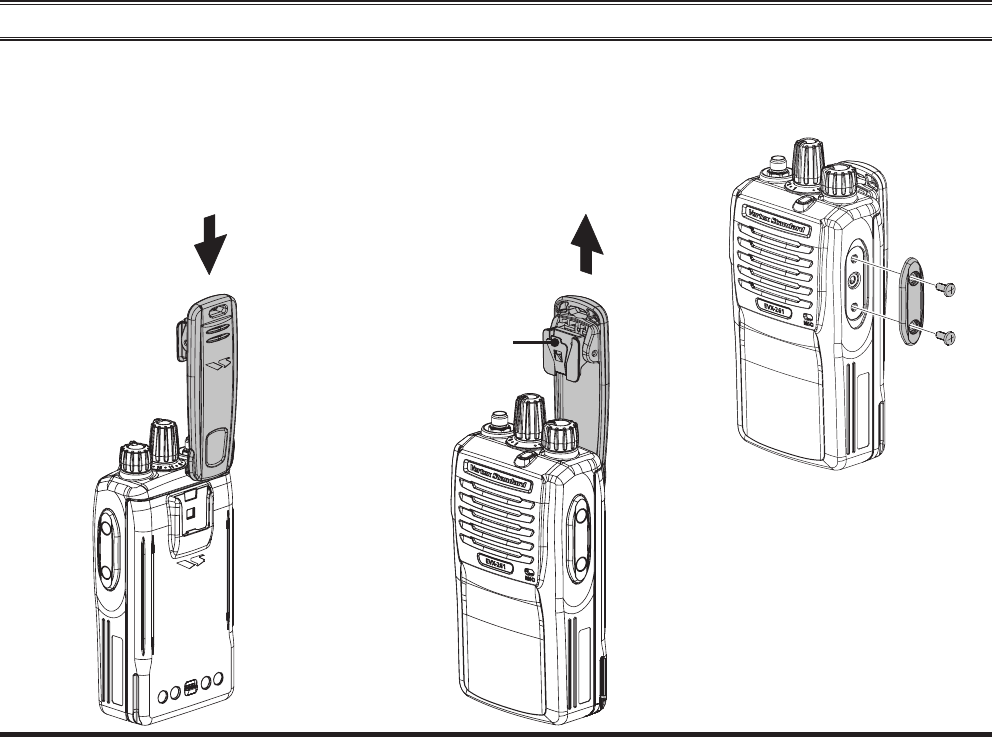
Belt Clip Installation and Removal
BEFORE YOU BEGIN
To install the Belt Clip: align the
Belt Clip to the groove of the Bat-
tery pack, then press the Belt Clip
downward until it locks in place
with a “Click.”
To remove the Belt Clip: use a
fl at head screw driver to press the
Belt Clip Tab away from the bat-
tery pack to unlock the Belt Clip,
then slide the Belt Clip upward to
remove it.
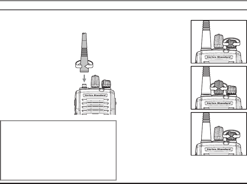
MIC/SP CAP Installation
Use only the supplied screws
when install the MIC/SP cap.
This radio does not keep the
Water Resistant Rating (IP55)
when the MIC/SP cap is not in-
stalled in the MIC/SP jack.
Install the MIC/SP cap with the sup-
plied screws.
Belt Clip Tab
Exhibit 8: Operating Manual
FCC ID: AXI11374720
IC: 10239A-11374720
Vertex Standard LMR, Inc.
10 EVX-261 OPERATING MANUAL
MIC/SP Jack
(External MIC/SP)
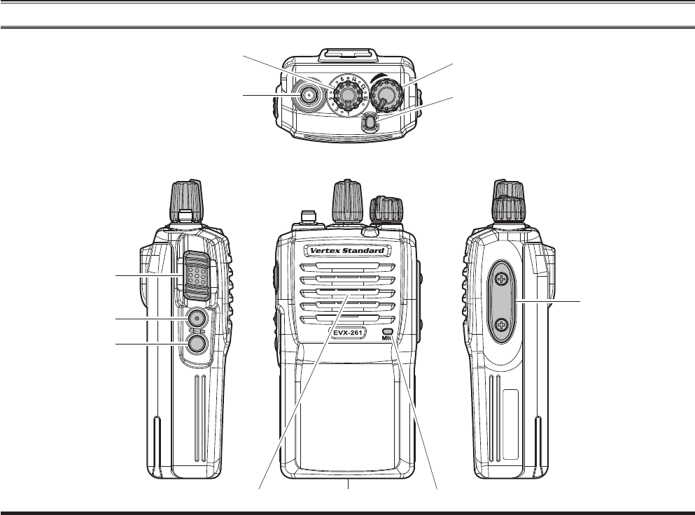
CONTROLS & CONNECTORS
LED Indicator (Programmable)
Default settings are:
Steady Red: Transmitting in progress
Blinking Green: Busy Channel
Steady Green: Tone Squelch in defeated condition
Blinking Red: Low Battery Power
PTT Switch
SIDE-1 Button
SIDE-2 Button
Speaker MicrophoneBattery Pack Latch
Antenna Jack
CH (Channel) Selector VOL (Volume)/PWR (Power) Knob
Exhibit 8: Operating Manual
FCC ID: AXI11374720
IC: 10239A-11374720
Vertex Standard LMR, Inc.
EVX-261 OPERATING MANUAL 11
OPERATION
Preliminary Steps
Install a charged battery pack onto the transceiver, as
described previously.
Screw the supplied antenna
onto the Antenna jack.
It is not recommended to oper-
ate this transceiver without an
antenna connected.
If you have a Speaker/Micro-
phone, we recommend that it
not be connected until you are
familiar with the basic opera-
tion of the EVX-261. Refer to
next page for more information
about Speaker/Microphone us-
age.
IMPORTANT NOTE
The water resistance rating of the transceiver (IP55)
is assured only when the following conditions are
met:
Battery pack is attached to the transceiver;
Antenna is connected to the antenna jack;
MIC/SP cap is installed in the MIC/SP jack.
Use of a speaker microphone in the MIC/SP
jack negates the IP55 rating.
Operation Quick Start
Turn the top panel’s
VOL/PWR knob clock-
wise to turn the radio on.
Turn the top panel’s CH
Selector knob to choose
the desired operating
channel.
Rotate the VOL/PWR
knob to set the volume
level. If no signal is
present, press (or press
and hold) the Program-
mable key (assigned to
the “SQL OFF” func-
tion: Normally SIDE-1 button); background noise will
now be heard, and you may use this to set the VOL/
PWR knob for the desired audio level. Press (or press
and hold) the Programmable key again to quiet the
Exhibit 8: Operating Manual
FCC ID: AXI11374720
IC: 10239A-11374720
Vertex Standard LMR, Inc.
12 EVX-261 OPERATING MANUAL
OPERATION
noise and resume normal
(quiet) monitoring.
To transmit, monitor the
channel and make sure it
is clear.
Press and hold the PTT
switch. Speak into the
microphone area of the
front panel grille in a
normal voice level. To return to the Receive mode, re-
lease the PTT switch.
Press (or press and hold)
the SIDE-1 or SIDE-
2 button to activate one
of the pre-programmed
functions programmed
using CE156 software
by your Vertex Standard
authorized dealer. See the next chapter for details re-
garding feature availability for this radio.
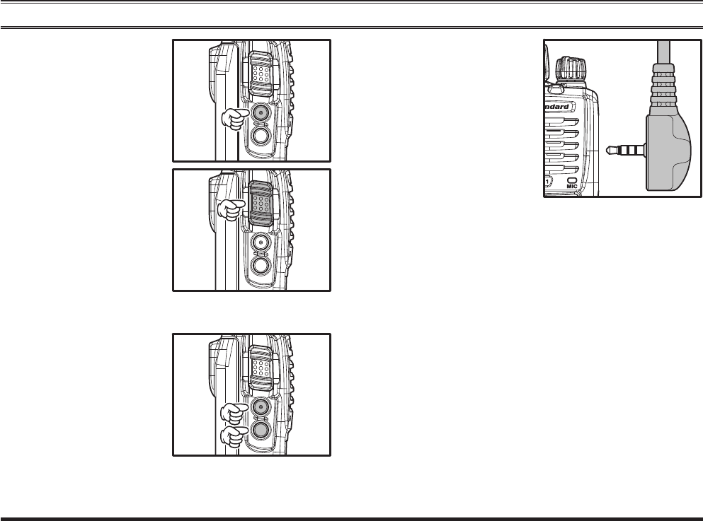
If a Speaker/Microphone
is available, remove the
plastic cap and its two
mounting screws from
the right side of the
transceiver, then insert
the plug of the Speaker/
Microphone into the
MIC/SP jack; secure
the plug using the screws supplied with the Speaker/
Microphone. Hold the speaker grille up next to your
ear while receiving. To transmit, press the PTT switch
on the Speaker/Microphone, just as you would on the
main transceiver’s body, and speak into the micro-
phone on a normal voice level.
Note 1): Save the original plastic cap and its mount-
ing screws. They should be reinstalled when not us-
ing the Speaker/Microphone.
2) When you press the PTT switch on the Speaker/
Microphone, it disables the internal microphone, and
vice versa.
This radio have two modes of DMR operation to max-
imize spectrum effi ciency. Standard operation requires
use of a TDMA repeater (such as the EVX-R70) to
utilize the repeater’s dual time slot capability for dou-
bling your radio fleet’s communication paths for up
Exhibit 8: Operating Manual
FCC ID: AXI11374720
IC: 10239A-11374720
Vertex Standard LMR, Inc.

EVX-261 OPERATING MANUAL 13
OPERATION
to two simultaneous transmissions. The second mode
is Direct mode, which enables two communications
paths on a single frequency, doubling your capacity
with only the subscriber radios. No repeater is neces-
sary when operating in Direct mode.
If the BCLO (Busy Channel Lockout) feature has been
programmed on an analog channel, the radio will not
transmit when a carrier is present. Instead, the radio
will generate short beep three times. Release the PTT
switch and wait for the channel to be clear of activity.
If the BTLO (Busy Tone Lockout) feature has been
programmed on an analog channel or CCLO (Color
Code Lockout) feature has been programmed on a dig-
ital channel, the radio can transmit only when there
is no carrier being received or when the carrier being
received includes the correct tone (CTCSS tone or
DCS code) on an analog channel or correct code on a
digital channel.
Digital Mode Specifi c Features
When operating on a digital channel, a priority user can
be assigned a variety of control functionality when pro-
grammed with the CE156 software. The control feature
descriptions are as follow:
Interrupt:
A priority user radio can interrupt a current transmis-
sion on an active channel, ending the transmission
prematurely and opening the channel for a priority or
critical message.
Stun:
A priority user (assigned when programming the ra-
dio) can temporarily disable or “stun” a radio in the
fleet if the radio has been compromised or is being
abused. The stunned radio can be revived using the
“Revive” command on the radio that initiated the stun
command.
Kill:
A priority user can completely disable or “kill” a radio
in the fl eet, preventing communication completely on
compromised radios. To revive the radio, the “killed”
radio must be returned to an authorized Vertex Stan-
dard Dealer.
Revive:
A stunned radio can be revived by a priority user
through the use of the “Revive” command.
Exhibit 8: Operating Manual
FCC ID: AXI11374720
IC: 10239A-11374720
Vertex Standard LMR, Inc.

14 EVX-261 OPERATING MANUAL
OPERATION
Remote Monitor:
A priority radio can force another radio in the fl eet to
open transmission for a pre-programmed period with
the CE156 software for the priority radio to hear any
audio on the radio being monitored.
For further details, contact your Vertex Standard dealer.
Note: The EVX-261 cannot control other radio by the
above features (decode only).
Automatic Time-Out Timer
If the selected channel has been programmed with an Au-
tomatic Time-Out Timer, any transmission is limited to a
fi xed transmit time, dictated when programming the radio
with CE156 software. A 10 second warning tone/beep
will sound before Automatic Time Out Timer is activated,
with a second tone/beep sounding when the radio offi-
cially reaches the pre-set maximum tranmission time. In
addition, the top panel red LED (“TX” indicator) light will
turn off and any transmission activity will stop. To re-
sume transmission, the user must release the PTT switch
and await expiration of the “penalty timer”.
Exhibit 8: Operating Manual
FCC ID: AXI11374720
IC: 10239A-11374720
Vertex Standard LMR, Inc.
EVX-261 OPERATING MANUAL 15
ADVANCED OPERATION
Programmable Key Functions
The EVX-261 provides two Programmable Function (PF)
keys: SIDE-1 and SIDE-2 keys.
Both PF keys can be customized, via programming by
your Vertex Standard dealer, to meet your communica-
tions/network requirements.
The possible PF key programming features are illustrated
at the right, and their functions are explained in more
detail in the next pages. For further details, contact your
Vertex Standard dealer.
In this chapter, the icon is used to indicate features
supported only in “Analog” mode. For features that are
available in both “Analog” and “Digital” modes, no icon
is shown.
For future reference, the table on the right side of the page
can be used to track each function assigned to the Pro-
grammable Function Keys on your radio.
FUNCTION
PROGRAMMABLE KEY
(PRESS KEY / PRESS AND HOLD KEY)
SIDE-1 SIDE-2
None / /
Monitor / /
Monitor -Momentarily- /--- /---
Low Power / /
Encryption / /
SQL OFF / /
SQL OFF -Momentarily- /--- /---
Beep OFF / /
Whisper / /
VOX / /
VOX Anti-Trip / /
Emergency /--- /---
Scan / /
Dual Watch / /
Follow-Me Scan / /
TA (Talk Around) Scan / /
Scan Set / /
Talk Around / /
Reset / /
Call / /
Call 1 / /
Call 2 / /
Call 3 / /
Speed Dial / /
Duty / /
Transmit Battery Saver Disable / /
Exhibit 8: Operating Manual
FCC ID: AXI11374720
IC: 10239A-11374720
Vertex Standard LMR, Inc.
16 EVX-261 OPERATING MANUAL
ADVANCED OPERATION
Description of Operating Functions SQL OFF
SQL OFF opens the radio squelch/unmute the audio to hear
background noise.
SQL OFF -MOMENTARILY-
Opens the SQL to hear background noise (unmute the
audio) while pressing the assigned PF key. This function
can not be assigned to a Long Press (LP) key function.
BEEP OFF
Activation of Beep off disables all radio beeps (alert tones)
temporarily. Radio beeps will be restored by pressing the
PF key again.
WHISPER
Whisper allows the user to increase the microphone gain,
allowing the operator to speak in a low voice (whisper)
temporarily when transmitting. The radio can go back to
normal microphone gain by pressing the assigned PF key
a second time.
VOX (REQUIRES OPTIONAL VOX COMPATIBLE HEADSET)
Enabling the VOX function will allow hands free, au-
tomatic voice activation of the transmitter as the micro-
phone picks up audio. The PTT switch does not need to
be pressed to open the channel when VOX is enabled.
All functions listed in this section can be assigned to any
PF Key. Up to two functions can be assigned per key,
with the feature being activated by:
Short Press (SP) - Press and release
Long Press (LP) - Press and hold
MONITOR
Any signaling features can be activated/deactivated by
an assigned PF key. The LED indicator will glow green
when the signaling feature is deactivated.
MONITOR -MOMENTARILY-
Cancel any signaling features while pressing the assigned
PF key. This function can not be assigned to a Long Press
(LP) key function.
LOW POWER
Low power mode reduces the transmitter to a lower power
for extension of battery life. Normal transmit power can
be achieved by pressing the Low power PF key a second
time.
ENCRYPTION
Analog Voice Inversion encryption can be activated/deac-
tivated by an assigned PF key.
Exhibit 8: Operating Manual
FCC ID: AXI11374720
IC: 10239A-11374720
Vertex Standard LMR, Inc.

EVX-261 OPERATING MANUAL 17
ADVANCED OPERATION
VOX ANTI-TRIP
VOX Anti-trip prevents the transceiver from activating a
VOX transmission from either internal or external radio
alert tones (radio beeps).
EMERGENCY
Emergency can either be programmed in analog or digital
mode. When the emergency key is pressed, activate the
pre-programmed functions programmed using CE156
software by your Vertex Standard authorized dealer, and
requests the assistance. For further details of the pre-pro-
grammed function, contact your Vertex Standard dealer.
This function can not be assigned to a Long Press (LP)
key function.
To revive the radio from the Emergency mode, just press
again the assigned PF key or turn off the radio.
SCAN
The Scanning feature is used to monitor multiple chan-
nels programmed into the transceiver. When scanning, the
transceiver will check each channel for the presence of a
signal and will stop on a channel if a signal is present.
Note: Your dealer may have programmed your radio to
stay on one of the following channels if you press the
PTT switch during scanning pause:
“Scan Pause” channel (“Talk Back”)
“Last Busy” channel
“Priority” channel
“User Programmed” channel (“Select Channel”)
The channel the CH selector knob is currently
tuned to.
DUAL WATCH
The Dual Watch feature is similar to the SCAN feature,
except that only two channels are monitored:
The current operating channel
The Priority channel.
To activate Dual Watch:
Press, (or press and hold), the assigned PF key to acti-
vate the Dual Watch feature.
The scanner will search the two channels and pause
when it fi nds a transmission on either channel.
Exhibit 8: Operating Manual
FCC ID: AXI11374720
IC: 10239A-11374720
Vertex Standard LMR, Inc.

18 EVX-261 OPERATING MANUAL
ADVANCED OPERATION
To stop Dual Watch:
Press, (or press and hold), the assigned PF key to dis-
able the Dual Watch feature. The radio receives the
channel which was selected by the CH Selector knob.
FOLLOW ME SCAN
The Follow Me Scan feature checks a user-assigned pri-
ority channel in addition to the channels previously pre-
programmed into a radio’s scan list. For example, if only
Channels 1, 3, and 5 (of the 8 available channels) are
designated for “Scanning”, the user may assign Channel 2
as the “user-assigned” priority channel via the Follow Me
Scan.
To activate Follow Me Scan, fi rst select the channel you
want to designate as the “user-assigned priority channel”
by positioning the CH Selector knob on the desired “pri-
ority” channel. Next, press, (or press and hold), the as-
signed PF key. Finally, rotate the CH Selector knob to the
desired “operating channel”.
The scanner will search the two channels (user-assigned
priority channel and operating channel) and pause when it
fi nds a transmission on either channel.
TA (TALK AROUND) SCAN
Press, (or press and hold), the assigned PF key to toggle
the TA Scan feature “On” and “Off”.
When operating on a duplex channel system (for example,
a repeater station), TA Scan allows the transceiver to
search both transmit and receive frequencies on your du-
plex system.
When a signal is encountered on the receive frequency,
the transceiver will pause until the signal disappears.
When a signal is encountered on the transmit frequency,
the transceiver will check for activity on the receive fre-
quency every few seconds (interval programmed by your
Vertex Standard dealer).
Note: The TA Scan feature does not activate on a Simplex
Channel.
SCAN SET
Scan Set enables the user to add or delete a current chan-
nel temporarily to a pre-programmed scan list.
TALK AROUND
Talk Around is most commonly utilized when operating
on duplex channel systems (separate receive and transmit
frequencies, common with use of a repeater station). The
Talk Around feature allows you to bypass the repeater
station and talk directly to a nearby station or transceiver.
This feature has no effect when you are operating on
“simplex” channels, where the receive and transmit fre-
quencies are already the same.
Exhibit 8: Operating Manual
FCC ID: AXI11374720
IC: 10239A-11374720
Vertex Standard LMR, Inc.
EVX-261 OPERATING MANUAL 19
Note that your dealer may have mode provision for “Talk
Around” channels by programming “repeater” and “Talk
Around” frequencies on two adjacent channels. If so, the
key may be used for one of the other Pre-Programmed
Functions.
RESET
When operating in the selective call feature, resets the
communication by an assigned PF key.
CALL
Send a pre-programmed 2 Tone call signal with a one
touch PF key.
CALL 1 TO CALL 3
Recalls the pre-programmed stations with a one touch PF
key.
SPEED DIAL
Your Vertex Standard dealer may have pre-programmed
Auto-Dial telephone number memories into your radio.
To dial a number:
Press, (or press and hold), the assigned PF key to send a
pre-defi ned DTMF tone. The DTMF tones sent during the
dialing sequence will be heard in the speaker.
DUTY
The Duty function is specifi c to paging operation. When
Duty mode is “ON” the user will hear all traffi c (specifi c
to sub audio signaling) on the paging channel. The paging
alert will sound when the programmed 2 Tone or 5 Tone
sub audio signal is received.
If Duty mode is “OFF”, normal radio traffi c is not heard
on the paging channel. The radio will only unmute and
sound the paging alert with the programmed 2 Tone or 5
Tone signal is received.
TRANSMIT BATTERY SAVER DISABLE
The Transmit Battery Saver helps extend battery life by
reducing transmit power when a very strong signal from
an apparently nearby station is being received. Caution
is advised when using this feature, as your transmission
power could degrade the audio heard by the receiving ra-
dios in your communication path.
Disabling the Transmit Battery saver by pressing (or press
and holding) the PF key is recommended if you are op-
erating in a location where high power is almost always
required.
Press again, (or press and hold again), the assigned PF
key, the Transmit Battery Saver activates to reduce the
transmit power when a very strong signal from an appar-
ently nearby station is being received.
ADVANCED OPERATION
Exhibit 8: Operating Manual
FCC ID: AXI11374720
IC: 10239A-11374720
Vertex Standard LMR, Inc.

20 EVX-261 OPERATING MANUAL
LOCK
In order to prevent accidental channel changes or inad-
vertent transmissions, various aspects of the CH Selec-
tor knob, Programmable keys, and PTT switch may be
locked. The precise lockout confi guration is programmed
by your Authorized Vertex Standard dealer.
To activate the locking feature, first turn the radio off.
Then, press and hold the PTT and SIDE-2 key while turn-
ing the radio on again.
To cancel the key locking, repeat this process.
ARTS™
(AUTO RANGE TRANSPOND SYSTEM)
This system is designed to inform the operator when you
and another ARTS™-equipped transceivers and stations
are within communication range using the DCS Encoder/
Decoder.
During ARTS™ operation, when the radio receives an
incoming ARTS™ signal, a short single beep will sound.
If you move out of range for more than two minutes, your
radio senses that no signal has been received, causing a
short triple beep to sound. Moving back into communica-
tions range, a short single beep will again sound as the
ARTS™ signal transmission from another transceiver or
station is back in range.
Exhibit 8: Operating Manual
FCC ID: AXI11374720
IC: 10239A-11374720
Vertex Standard LMR, Inc.
21EVX-261 OPERATING MANUAL
OPTIONAL ACCESSORIES
FNB-V133LI-UNI
7.4V DC , 1380 mAh Li-Ion Battery Pack
FNB-V134LI-UNI
7.4V DC , 2300 mAh Li-Ion Battery Pack
FNB-V136-UNI
7.2V DC , 1200 mAh Ni-MH Battery Pack
CD-58
Desktop Charger
PA-55
AC Adapter for CD-58
VAC-UNI
Desktop Charger (CD-58 + PA-55)
VAC-6058
Multi-Unit Charger
MH-37A4B-1
Earpiece Microphone
MH-66A4B
Noise Cancelling Speaker Microphone
MH-100
Receive Only Earpiece
(for MH-45B4B, MH-360S, & MH-450S)
MH-101A4B
1 Wire Surveillance Kit
MH-102A4B
2 Wire Surveillance Kit
MH-103A4B
3 Wire Surveillance Kit
MH-201A4B
Heavy Duty Headset
MH-360S
Compact Speaker Microphone
MH-450S
Speaker Microphone
VH-150A
Behind Type VOX Compatible Microphone
VH-150B
Over the Head VOX Compatible Microphone
VCM-5
Vehicular Charger Mounting Adapter
for CD-58
ATV-8A
VHF Antenna (134-151 MHz)
ATV-8B
VHF Antenna (150-163 MHz)
ATV-8C
VHF Antenna (161-174 MHz)
ATV-6XL
VHF Antenna (Untuned)
ATU-6A
UHF Antenna (400-430 MHz)
ATU-6B
UHF Antenna (420-450 MHz)
ATU-6C
UHF Antenna (440-470 MHz)
ATU-6D
UHF Antenna (450-490 MHz)
ATU-6F
UHF Antenna (490-520 MHz)
ATU-6DS
UHF Stubby Antenna (450-490 MHz)
CN-3
Antenna Adapter
CLIP-20
Belt Clip
LCC-261*
Leather Case, Belt Loop
(for FNB-V133LI-UNI)
LCC-261H*
Leather Case, Belt Loop
(for FNB-V134LI-UNI & FNB-V136-UNI)
LCC-261S
Leather Case, Swivel Belt Loop
(for FNB-V133LI-UNI)
LCC-261SH
Leather Case, Swivel Belt Loop
(for FNB-V134LI-UNI & FNB-V136-UNI)
CE156
PC Programming Software
FIF-12
USB Programming Interface
CT-106
Connection Cable for FIF-12
CT-27
Radio to Radio Cloning Cable
Availability of accessories may vary; some ac-
cessories are supplied standard per local re-
quirements, others may be unavailable in some
regions. Check with your Vertex Standard Dealer
for changes to this list.
*Note: To add in after ship acceptance for EME Test.
Exhibit 8: Operating Manual
FCC ID: AXI11374720
IC: 10239A-11374720
Vertex Standard LMR, Inc.

22 EVX-261 OPERATING MANUAL
WARRANTY POLICY
Vertex Standard warrants, to the original purchaser only, its Vertex Standard manufactured communications products
against defects in materials and workmanship under normal use and service for a given period of time from the date of pur-
chase.
Limited Warranty Details:
North America customers (USA and Canada): http://www.vertexstandard.com/lmr/warranty-terms.aspx
Customers outside of North America: contact the authorized Vertex Standard distributor in your country.
Exhibit 8: Operating Manual
FCC ID: AXI11374720
IC: 10239A-11374720
Vertex Standard LMR, Inc.

EVX-261 OPERATING MANUAL 23
NOTE
Exhibit 8: Operating Manual
FCC ID: AXI11374720
IC: 10239A-11374720
Vertex Standard LMR, Inc.

24 EVX-261 OPERATING MANUAL
NOTE
Exhibit 8: Operating Manual
FCC ID: AXI11374720
IC: 10239A-11374720
Vertex Standard LMR, Inc.
Part 15.21: Changes or modifi cations to this device not expressly approved by Vertex Standard could void the user’s
authorization to operate this device.
The AMBE+2™ voice coding Technology embodied in this product is protected by intellectual property rights in-
cluding patent rights, copyrights and trade secrets of Digital Voice Systems, Inc. This voice coding Technology is
licensed solely for use within this Communications Equipment. The user of this Technology is explicitly prohibited
from attempting to decompile, reverse engineer, or disassemble the Object Code, or in any other way convert the
Object Code into a human-readable form.
U.S. Pat. Nos. #5,870,405, #5,826,222, #5,754,974, #5,701,390, #5,715,365, #5,649,050, #5,630,011, #5,581,656,
#5,517,511, #5,491,772, #5,247,579, #5,226,084 and #5,195,166.
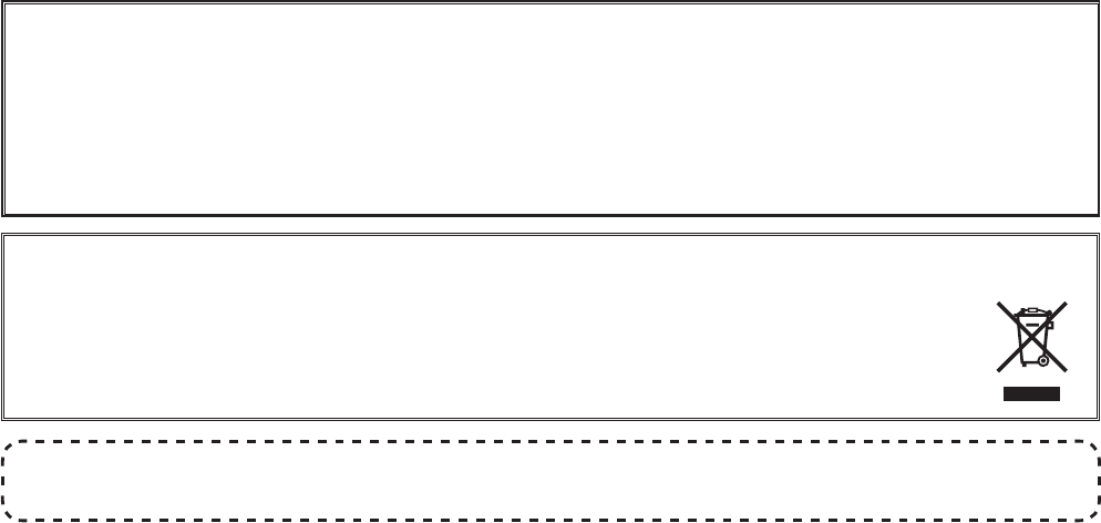
DISPOSAL OF YOUR ELECTRONIC AND ELECTRIC EQUIPMENT
Products with the symbol (crossed-out wheeled bin) cannot be disposed as household waste.
Electronic and Electric Equipment should be recycled at a facility capable of handling these items and
their waste by products.
In EU countries, please contact your local equipment supplier representative or service center for informa-
tion about the waste collection system in your country.
Exhibit 8: Operating Manual
FCC ID: AXI11374720
IC: 10239A-11374720
Vertex Standard LMR, Inc.

No portion of this manual may be reproduced without the per-
mission of Vertex Standard LMR, Inc.
Vertex Standard is a trademark of Vertex Standard LMR, Inc.
All other trademarks are the property of their respective owners.
©2016 Vertex Standard LMR, Inc.
All rights reserved.
Vertex Standard LMR, Inc.
4-6-8 Shibaura, Minato-ku, Tokyo 108-0023, Japan
Exhibit 8: Operating Manual
FCC ID: AXI11374720
IC: 10239A-11374720
Vertex Standard LMR, Inc.