Vertex Wireless VW240 CDMA 1xEVDO Rev.A Wireless Router User Manual VW200 manual v1 39 090512
Vertex Wireless Co., Ltd. CDMA 1xEVDO Rev.A Wireless Router VW200 manual v1 39 090512
UserManual.wiki
>
Vertex Wireless
>
VW240 User Manual
Users Manual
Navigation menu
Upload a User Manual
Namespaces
Wiki Guide
HTML
PDF
Info
Views
User Manual
Discussion / Help
Navigation
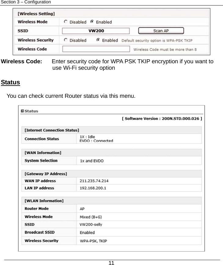
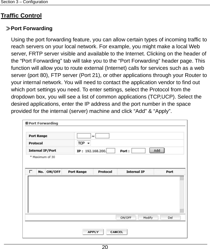
![10 Section 3 – Configuration Basic setup Connection Setting [Internet Setting] Basic setting: Enter your PPP user name, password and Dial (Provided by operator. Default dial: #777) System Selection: Select the CDMA system from the drop-down menu: 1x and EVDO, 1x, and EVDO [Wireless Setting] Wireless Mode: Select Enabled to use Wi-Fi feature otherwise select Disabled. If you select Enabled, SSID and Wireless Security will be displayed below SSID: Service Set Identifier is the name of your wireless network. Create a name using up to 32 characters. Wireless Security: Select Enabled to use Wireless Security otherwise select Disabled. If you select Enabled, Wireless Code will be displayed below (Default security option is WPA-PSK TKIP. If you want to have more option, go to Wireless Setup under Advanced Setup)](https://usermanual.wiki/Vertex-Wireless/VW240/User-Guide-1116827-Page-11.png)
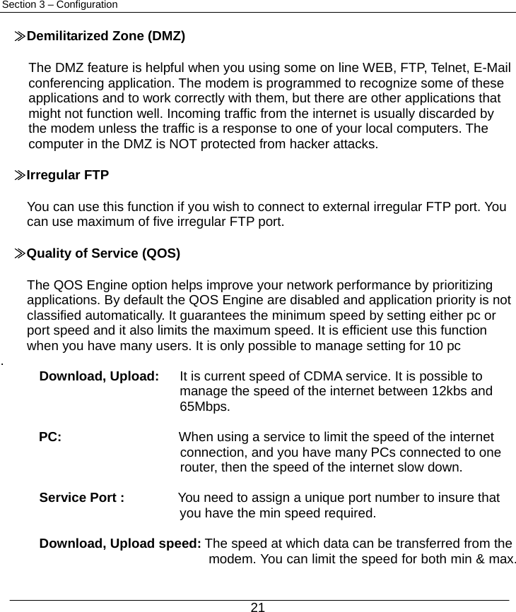
![12 Section 3 – Configuration Advanced Setup This menu provides various enhanced network function configuration and recommend to expert user. It’s not necessary for all users. IP Setup ≫ Internet Setting [Internet Setting] Basic setting: Enter your PPP user name, password and Dial (Provided by operator. Default dial: #777) System Selection: Select a CDMA system from the drop-down menu: 1x and EVDO, 1x, and EVDO](https://usermanual.wiki/Vertex-Wireless/VW240/User-Guide-1116827-Page-13.png)
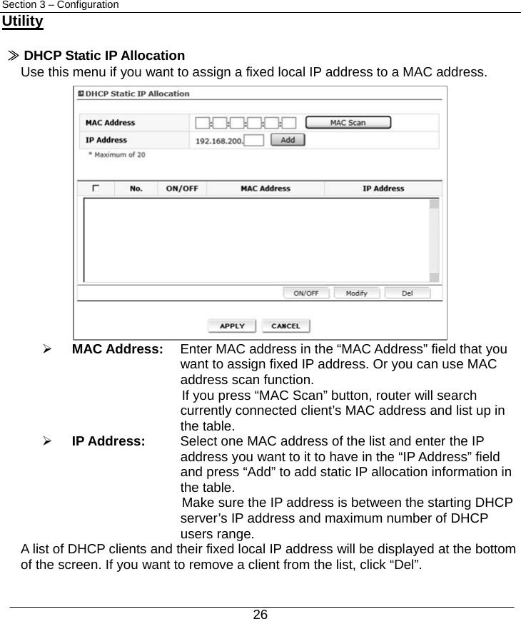
![13 Section 3 – Configuration [Dynamic IP] DNS Server: Select either Manual or Auto select for DNS server. Primary DNS Address: Enter the Primary DNS server IP assigned by your ISP Secondary DNS Address: Enter the Secondary DNS server IP assigned by your ISP (optional) MTU: Maximum Transmission Unit – you may need to change the MTU for optimal performance with your specific ISP. Automatic is the default MTU ≫ LAN Setting IP Address: This is the internal IP address of the Router. The default IP address is “192.168.200.1” and it can be changed if needed. Subnet Mask: This is a unique, advanced feature of the Router. The default is “255.255.255.0” and it can be changed if needed. DHCP Server: The Dynamic Host Control Protocol (DHCP) server will automatically assign an IP address to the computers on the LAN/private network. Select Enabled to use DHCP server otherwise select Disabled](https://usermanual.wiki/Vertex-Wireless/VW240/User-Guide-1116827-Page-14.png)
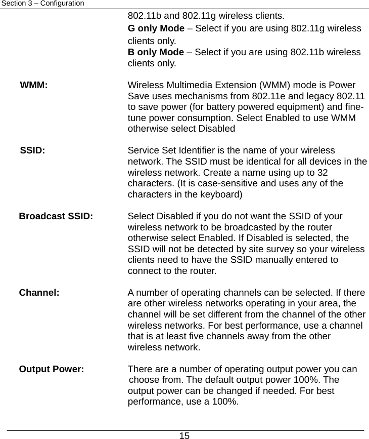
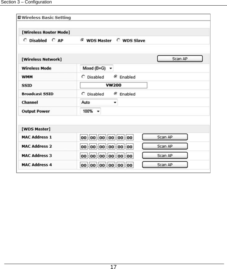
![14 Section 3 – Configuration Note: To use DHCP server, be sure to set your computers to be DHCP clients by setting their TCP/IP settings to “Obtain an IP Address Automatically. DHCP IP Pool: Enter the starting and ending IP addresses for the DHCP server’s IP assignment. The default range is 100-200. Wireless Setup ≫ Wireless Basic Setting [Wireless Router Mode] Select a Wireless Router mode from the list: Disabled / AP / WDS Master / WDS Slave [Wireless Network] Wireless Mode: Select a Wireless Mode from the drop-down menu: Mixed(B+G) Mode – Select if you are using both](https://usermanual.wiki/Vertex-Wireless/VW240/User-Guide-1116827-Page-15.png)
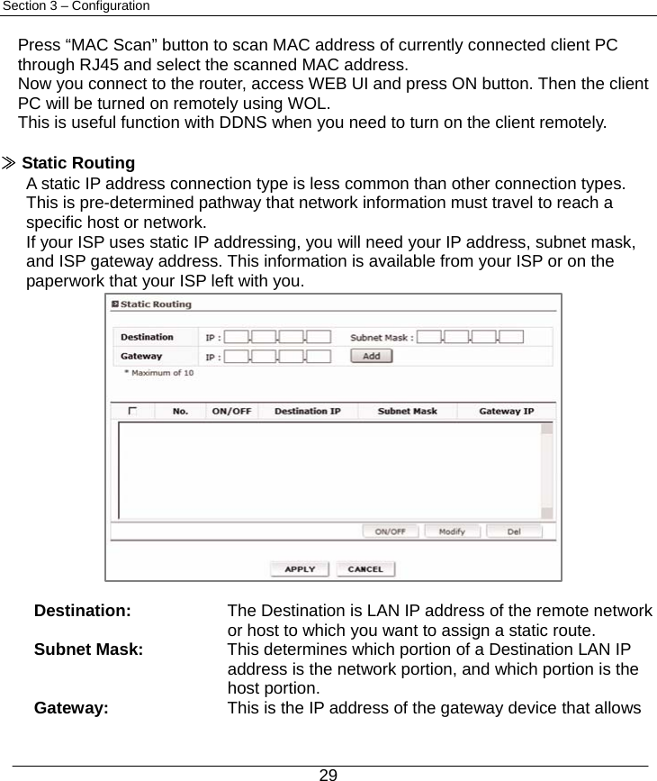
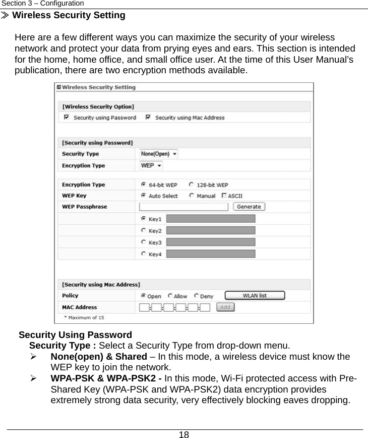
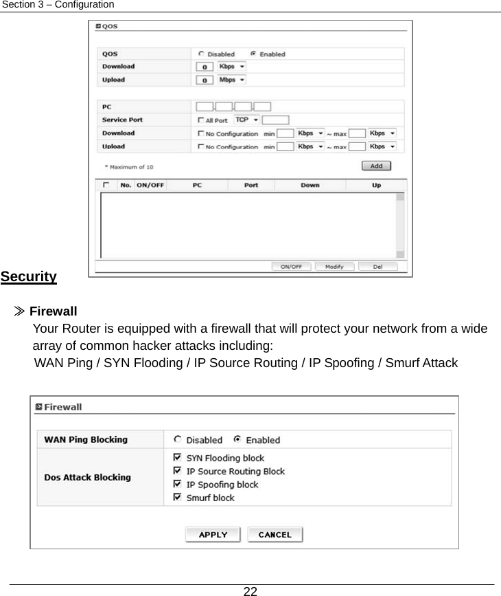
![16 Section 3 – Configuration ≫ Wireless Distribution System(WDS) Master & Slave WDS is a system that enables the wireless interconnection of access points in network. It allows a wireless network to be expanded using multiple access points without need for a wired backbone to link them. It is possible to extend wireless coverage area by using more than two VW-200 (Maximum 4). WDS can be either a WDS master or remote WDS slave. WDS Master relays data between remote WDS slave, wireless clients or other relay station to either a main or other relay WDS slave. WDS Master & Slave must be configured as same SSID, Channel and security. Note : When you setup WDS function, please disable wireless security options of every AP’s. WDS function of VW200 series is applicable with other APs which use Ralink chipset but function can be restricted for other wireless chipset. ¾ Setting Wi-Fi security : Disable Wi-Fi security option in each units. (You can set security option in WDS mode but recommend to set security after WDS configuration. Also you should set same security option in each Master and Slave unit.) ¾ WDS Master Setting : Master mode should be set in the unit which is working with EVDO network for WAN. Connect to WEB UI using IP address, “192.168.200.1”. Go to [Advanced Set up] -> [Wireless Set up] -> [Basic setting]. Click [WDS Master] -> Set desired SSID and Channel. (These SSID and Channel should be same with WDS slave device.) Click “Scan AP” in WDS Master section -> Choose AP that you want to use as WDS Slave -> Click “Apply” to apply your configuration. ¾ WDS Slave Setting : Connect to WEB UI using IP address, “192.168.200.1” which you want to use as WDS slave. Go to [Advanced Set up] -> [Wireless Set up] -> [Basic setting]. Click [WDS Slave] Æ Set desired SSID and Channel. (These SSID and Channel should be same with WDS Master device.) Set desired IP address of WEB UI. (Once device is operated as WDS slave, you can access WEB UI via this address.) Click “Scan AP” in WDS Slave section -> Choose AP that you want to use as WDS Master -> Click “Apply” to apply your configuration.](https://usermanual.wiki/Vertex-Wireless/VW240/User-Guide-1116827-Page-17.png)
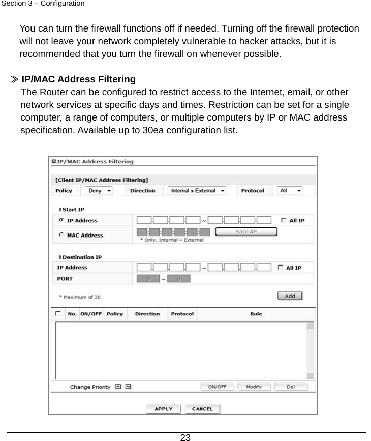
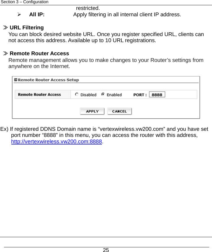
![24 Section 3 – Configuration [Client IP/MAC Address Filtering] Policy : Select filtering policy Deny or Allow Direction ¾ Internal to External: Select if you want to apply filtering policy in the outgoing communication. (All clients are allowed in case of outgoing communication by default) ¾ External to Internal: Select if you want to apply filtering policy in the incoming communication. (All clients are restricted in case of incoming communication by default. Hence this option is valid in case of DMZ or IP Forwarding) Protocol : Select one among of TCP / UDP / ALL. If you select ALL option, filtering policy will be applied in all protocol. Start IP Internal to External ¾ IP Address : Configure internal client IP address to be restricted by filtering policy. ¾ All IP: Apply filtering policy in all clients. ¾ MAC Address: Configure internal client MAC address to be restricted by filtering policy. You can scan client MAC address using Scan AP button. External to Internal ¾ IP Address: Configure external IP address to be restricted by filtering policy. ¾ All IP: Apply filtering policy in all external IP address. ¾ MAC Address: Not available in this option. Destination IP Internal to External ¾ IP Address/PORT: Configure external IP address and Port to be restricted. ¾ All IP : Apply filtering in all external IP address. External to Internal ¾ IP Address/PORT: Configure internal client IP address and Port to be](https://usermanual.wiki/Vertex-Wireless/VW240/User-Guide-1116827-Page-25.png)