Vertex Wireless VW440 CDMA EV-DO Rev.A Terminal User Manual VW400 User Manua Eng v0 6
Vertex Wireless Co., Ltd. CDMA EV-DO Rev.A Terminal VW400 User Manua Eng v0 6
UserManual.wiki
>
Vertex Wireless
>
VW440 User Manual
user manual
Navigation menu
Upload a User Manual
Namespaces
Wiki Guide
HTML
PDF
Info
Views
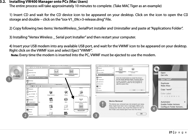
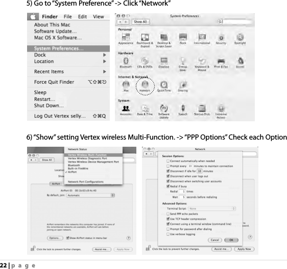
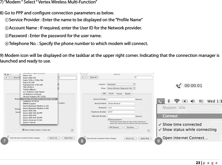
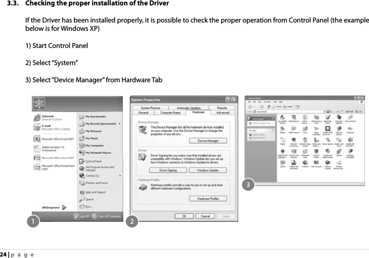
User Manual
Discussion / Help
Navigation