ViVOtech VPS500A Low Power Transmitter Wireless Card Reader User Manual ViVOpay 4000 OEM Technical Reference
ViVOtech, Inc. Low Power Transmitter Wireless Card Reader ViVOpay 4000 OEM Technical Reference
ViVOtech >
Users Manual

ViVOpay OEM S500 Technical Reference
TableofContents
PRODUCTOVERVIEW............................................................................................................................ 3
OVERVIEW ................................................................................................................................................. 3
FEATURES .................................................................................................................................................. 3
READERINSTALLATION ...................................................................................................................... 4
PHYSICALPLACEMENT ............................................................................................................................. 4
ORIENTATIONOFREADERPCAS............................................................................................................. 5
CONNECTINGTOAHOST ......................................................................................................................... 5
APPLYINGPOWER ..................................................................................................................................... 6
READEROPERATION ............................................................................................................................. 7
PRESENTINGCARDS/TAGS........................................................................................................................ 7
RS‐232OPERATION................................................................................................................................... 7
MAGNETICSTRIPECARDREADEREMULATION ...................................................................................... 8
MAGNETICSTRIPCARDEMULATION....................................................................................................... 8
TROUBLESHOOTING ............................................................................................................................. 9
APPENDICES............................................................................................................................................ 10
APPENDIXA‐PERFORMANCESPECIFICATIONS..................................................................................... 10
APPENDIXB‐COMPONENT&PIN‐OUTDETAIL.................................................................................... 11
APPENDIXC‐DIMENSIONSANDCLEARANCES..................................................................................... 14
Document:740‐0005‐001Rev1.02Proprietary&Confidential

ViVOpay OEM S500 Technical Reference
Document:740‐0005‐00Rev.1.03Proprietary&Confidential
ProductOverview
TheViVOpayOEMS500VendingReader(theReader)isanelectronicmodulecapableof
communicatingwithISO14443TypeAandTypeBcompatiblecardsandtagsusingRadio
Frequency(RF).DatastoredonthecardsandtagsisreadbytheReaderandtransmitted
toahost.ThissectionprovidesgeneralinformationabouttheReader.RefertoAppendix
A,B,andCfortechnicaldetails.
Overview
TheReaderconsistsofasetofprintedcircuitboardsconsistingofaControlPCAand
anAntennaPCA.Thetwocircuitboardstogethercontainallcircuitryrequiredto
communicatewithbetweenthehostandRFIDcardsandtags.AnoptionalInterface
PCAmaybeconnectedtotheControlPCAtoaddadditionalReadertoHost
configurations.Allcircuitboardsaredesignedtobeassembledasasinglemodule
forsimplemounting,ortheymaybeseparatedtoaccommodatespaceconstraints.
TypeA&BcardsandtagsdonotcontaininternalpowerandareactivatedbytheRF
powertransmittedbytheReader.Whenacardortagispositionedclosetothe
antennathecard/tagispoweredandactivated,andittransmitsitsdataasa
modulatedRFsignaltotheRFreceiver.TheRFreceiverdemodulatesthesignaland
sendsthedemodulatedtagdatatothemicrocontroller.Themicrocontrollercollects
thetagdata,decryptsit(ifrequired),andtransmitsittothehostterminal.TheLEDs
andbeeperindicatewhenataghasbeenreadsuccessfully.
Features
• ReadofISO14443TypeA&TypeBcardsandtags.
• ARMLPC212432‐bitMicrocontroller.
• CryptodataprocessingforcontactlessSmartcards(optional).
• RS‐232(9600,19200,38,400,57,600baud)
• MagneticStripeCardandMagneticStripeCardReaderemulation.
• Horizontal(4)orVertical(3)LEDindicators,orexternalLEDdrive.
• Beeperorexternalbeeperdrive.
• Fieldreplaceablefirmware.
• CompactpackagingfitsinthespaceofatypicalCardReaderorBillCollector.
• ExpandableinterfaceforusewithcustomInterfacePCAs.
ViVOpay OEM S500 Technical Reference
ReaderInstallation
ThissectiondescribeshowtoinstalltheViVOtechS500OEMVendingReaderintoavending
orterminalsystem.Installationwillvarydependinguponthespecificuseoftheproduct.
PhysicalPlacement
BecausetheReaderreliesonradiofrequencycommunications,thereadercanbe
susceptibletoelectricalinterferenceandaffectedbymetalmaterials.Therefore,for
optimalperformance,pleaseobservethefollowingimportantguidelinesbefore
physicallylocatingormountingtheReader.
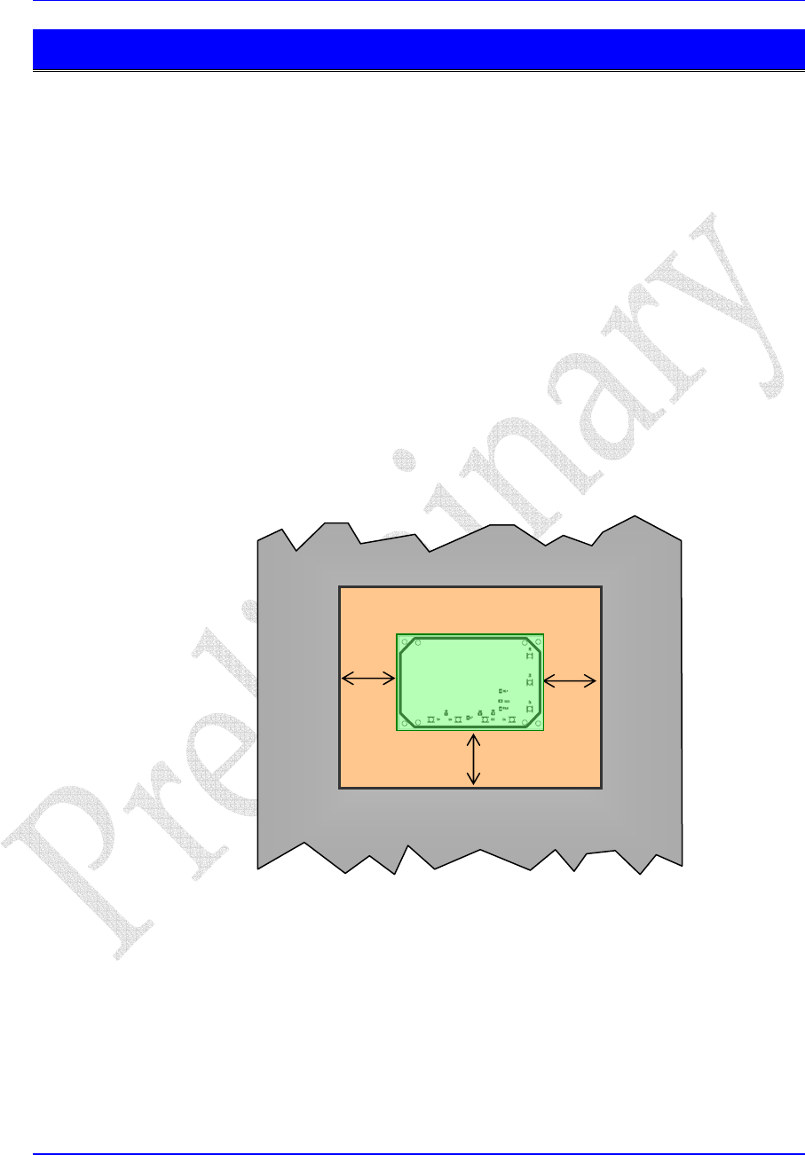
• DonotpositiontheAntennaPCBonanymetalsurfaceorwithinapproximately
2inches(5cm.)inanydirectionofanygroundedmetalsuchasmetalshelving,
steelbeams,orelectricalconduit.WhenattachingtheReadertoametallicface
panelframetheAntennawithanon‐metallicmaterialasshownbelowtoensure
clearancewiththemetal.
MetalFrame
2”
Plasticorothernon‐
metallicmaterial
2” 2”
Antenna
• DonotplacetheReaderPCBinthenearvicinityofbroadspectrumEMInoise
sources(suchasmotors,pumps,powersupplies,lightdimmers,CRTs,etc.).
• AvoidsourcesofRF(suchascellulartelephones,portable2‐wayradios,etc.)
whichmayreducetheabilityofthereadertocommunicatewiththetag.
• MakesurethatallcablesandwiringassociatedwiththeReaderisatleast6
inches(15cm.)awayfromothercablingandwiring(suchasACpowercables
fromotherelectricaldevices,computerdatacabling,telephonewiring,orwiring
associatedwithelectric‐poweredlockingmechanisms).
Document:740‐0005‐00Rev.1.04Proprietary&Confidential
ViVOpay OEM S500 Technical Reference
OrientationofReaderPCAs
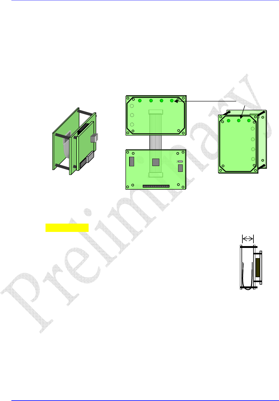
ThephysicaldesignoftheReaderprovidesforstackingofthePCAsusingstandoffs
toformasingleunitrequiringavolumeassmallas10cuin.However,ifspace
constraintsormountingconfigurationsdonotsupportastackedassemblythe
individualPCAsmaybemountedseparatelysuchassidebyside.Dualmounting
holesareprovidedonboththeAntennaPCAandControlPCAtoaccommodate
variousmountingconfigurations.Additionally,theAntennaPCBcontainsboth
horizontal(4)andvertical(3)LEDplacementandmaybeorientedassuch.
Antenna
LEDs
Control
StackedConfigurationHorizontal/SeparatedVerticalLEDOrientation
IMPORTANT:WhenconfiguringtheAntennaand
Controlboardsinastackedconfigurationthedistance
betweenthetwoboardsiscriticalwithrespecttotheread
rangeofcardsandtags.Itisrecommendedtheboards
areplacednocloserthan1”(2.54cm.)toachievetypical
readrangewithmostcards.Somecards/tagsmayrequire
moredistancebetweentheboards.Alwaysusenon‐
metallicstandoffstoconnecttheboardstogether.
2.54cm.min.
ConnectingtoaHost
TheconnectionfromtheReadertotheHostdependsupontheconfigurationdesired.
TheJ2connectorontheControlPCAcontainsalldatasignalsalongwithinput+5V
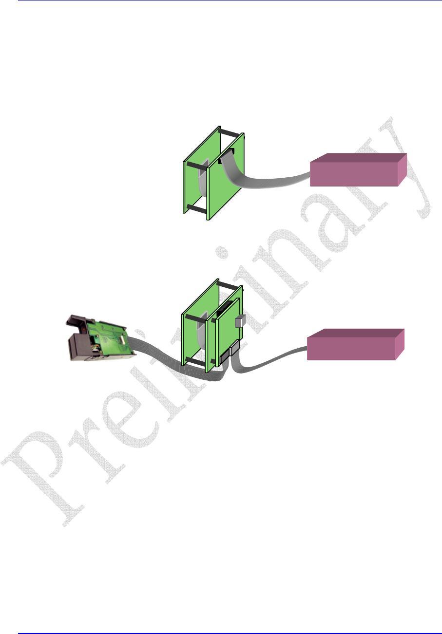
power.FortypicalRS‐232communicationsorwhentheReaderperformsasasingle
MagneticStripeCardReaderthenconnectfromJ2ontheControlPCAtothehost.
Refertothediagrambelow.
IfaddingtheReaderintoasystemwithanexistingmagneticstripecardreaderthen
anadditionaloptionalInterfacePCAisrequired.WiththisconfigurationtheReader
Document:740‐0005‐00Rev.1.05Proprietary&Confidential
ViVOpay OEM S500 Technical Reference
multiplexesthecardreadersignalsfromitselfandtheexistingcardreaderand
passesthemtothehost.TheReaderisinvisibletothehostandbehaveslikethe
existingmagneticcardreader.Thisconfigurationrequiresasecondcableidenticalto
theoneconnectingtheexistingcardreadertothehost.Connectthecablefromthe
existingcardreadertotheJ1connectorontheInterfacePCA,andconnectthesecond
cablefromtheJ2connectortothehost.Thehostdoesnotneedanyotherchange.
NotetheHostControllermustsupply+5VDCtobothdevices.
HostController
RS‐232orSingleEmulatedMagneticCardReaderConnections
HostController
DualMagneticCardReaderConnections
ApplyingPower
TheViVOpayOEMS500doesnothaveaswitchtoturnon/offpower.After
connectingthecablefromtheReadertothehostapplypowertothehostand/or
powersupply.TheReaderwillperformapower‐upsequenceasfollows:
• AllLEDswillilluminateaninternalself‐testisbeingperformed.
• ThedefaultRS‐232parameters(19,200bps,8data,1stop,noparity)willbeset.
• Ifself‐testandinitializationissuccessfulthebeeperwillemittwoshortbeeps
andtheleftmostLEDwillremainilluminatedindicatingtheReaderisready.
Withthepower‐upsequencesuccessfullycompleted,theunitwillreadavalidcard
ortagifpresentedandsendthedatatothehost.
Document:740‐0005‐00Rev.1.06Proprietary&Confidential

ViVOpay OEM S500 Technical Reference
Document:740‐0005‐00Rev.1.07Proprietary&Confidential
ReaderOperation
ThissectiondescribeshowtopresentcardsandtagstotheReaderandobtainthedataread
fromthecard.
PresentingCards/Tags
PresentingacardortagtotheReadersoitcanbereadissimple.Simplybringthe
card/tagwithinafewcentimetersoftheantenna.ItisalsoOKtogentlytouchthe
cardontheantenna.Presentacard/tagsothatitsmaximumsurfaceareaisparallel
totheantennatoobtainthebestreadrange.
Ifacard/tagisreadsuccessfullythebeeperwillemitasinglebeepand,ifconnected,
allLEDsontheAntennaPCAwillilluminate(theleftmostLEDremainsonto
indicatepower,theothersilluminatebriefly).Ifacardisnotreadsuccessfullyno
beepwilloccurnorwilltheLEDsflash.
Notethatonlyonecard/tagcanbeintheantenna’sfieldatagivetime.Oncea
card/taghasbeenreaditmustberemovedfromtheantenna’sfield(about6in.or15
cm.)foratleast1secondandthenpresentedagaintobereadagain.However,
differentcards/tagscanbereadatlessthan0.5secondintervals.
Afteracard/taghasbeenreadsuccessfullytheReaderwillstoreitsdatainthebuffer
andsendittothehostthroughtheRS‐232interface,theMagneticCardReader
interface,andthroughtheStripDriveinterface.
RS‐232Operation
RS‐232communicationsusetheJ2signalsRXandTXtosendandtransmitserialdata
to/fromthehost.Noflowcontrolisusedwith8bitsofdata,1stopbit,andnoparity.
Baudratesare9600,19200(default),38,400,and57,600.
Thedefaultserialmodeis“Burst”whichautomatically(withoutahostcommand)
transmitsthedatatothehostwhenavalidcard/tagisread.RefertotheViVOPay
SerialPortInterfacedocumentfordetailsonserialpacketformattingandotherserial
interfacecommands.
ViVOpay OEM S500 Technical Reference
MagneticStripeCardReaderEmulation
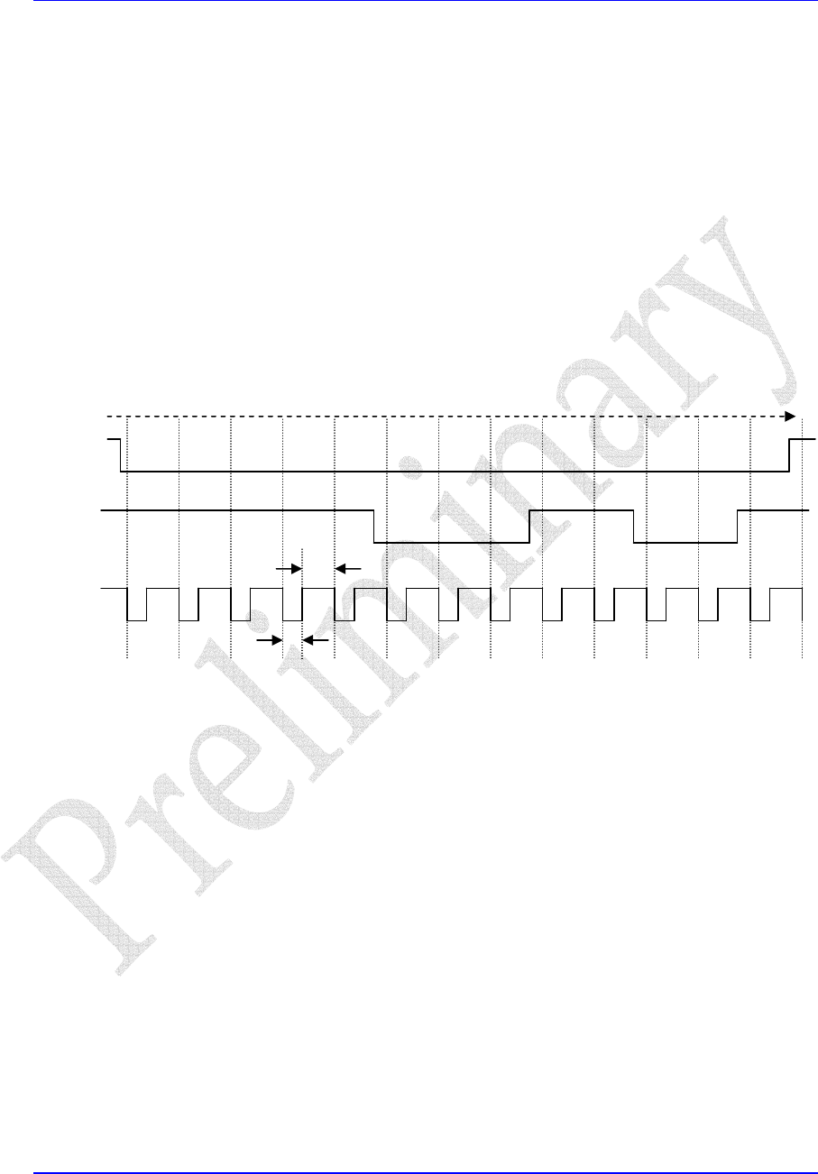
TheReaderemulatesaMagneticStripeCardReaderbysendingthedatareadfroma
card/tagoutasTrack1andTrack2datausingthe–IT1D,–IT1CLK,–IT2D,–IT2CLK,
and–ICPsignalslocatedatJ2ontheControlPCA.TheoutputsignalsareTTL(+5V)
levels.
Datareadfromacard/tagissenttothehostonlyifvalidTrack1and/orTrack2data
ispresentonthecard.Track1dataissentusingthe–IT1D,–IT1CLKsignals;Track2
dataissentusingthe–IT2Dand–IT2CLKsignals.DataisvalidforbothTrack1and
Track2whenthe–ICPsignalisactive.
ThetimingdiagrambelowillustratesthetimingusedwithMagneticCardemulation.
Thetimingrepresentsanaveragecardswipingspeedof20cm/s.
t0
0000 0 1 1 1 0 0110
720usec.
480usec.
‐ICP
‐ITD
‐ITCLK
EmulatedMagneticCardReaderTiming
MagneticStripCardEmulation
TheReadercanalsooutputTrack1andTrack2magneticstripeF2Fencodeddata
whichcanbeinjectedintotheheadsofamagneticstripcardreaderandreadbyit.
LowpowerTrack1andTrack2analogdataisoutputontheJ2StripDrivesignals
TRACK1andTRACK2.HighPowerStripDrive9Vdifferentialsignalsareoutputon
TRACK2+andTRACK2‐.NotethatoperationoftheHighPowerStripDrivesignals
requiresanadditional9VDC,500ma.powerinputonJ2pin4.
Document:740‐0005‐00Rev.1.08Proprietary&Confidential
ViVOpay OEM S500 Technical Reference
Document:740‐0005‐00Rev.1.09Proprietary&Confidential
Troubleshooting
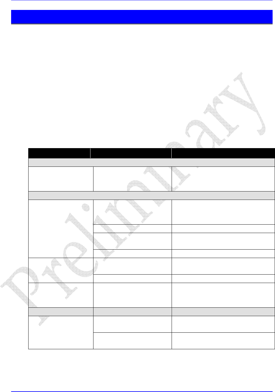
Therearenouser‐serviceablepartswithinthereader.IftheReaderdoesnotoperate
properlywheninstalledaccordingtoinstructionsusetheTroubleshootingTablebelowto
helpsolvesimpleproblems.Ifthecauseoftheproblemstillcannotbedetermined,you
maycontactourTechnicalSupportStaffatthenumberslistedbelow.Pleasehavethe
modelnumberandserialnumbersavailable.
TelephoneCustomerSupport
(888)363‐3753
TroubleshootingTable
SymptomPossibleCauseProbableCauseandRemedy
GeneralIssues
Readerdoesnotseem
tobepowered(no
LEDslit).
Readernotpoweredor
incorrectvoltage
• Checkcableconnections.
• Ensurepowerisonandcorrect
voltageandcurrentispresent.
ReadingCards/Tags
Cards/tagsnotpresented
properly
• Presentcard/tagcloserto
antenna.
• Ensurevalidcards/tagsused.
Powersupplyvoltage • Ensurevoltage/currentcorrect.
MetalorRFinterference• EnsurenometalorRF
interferenceisnearunit.
LEDsdonotlight
andbeeperdoesnot
soundwhenany
card/tagispresented.
Wrongfirmware• Ensurecorrectfirmware
Seecausesaboveforno
cards/tagsread.
• Seeremediesaboveforno
cards/tagsread.
Somecards/tagsare
read,butnotall.
Possiblebadcard/tag• Checkifcard/tagdamaged.
Canreadall
cards/tags,butonly
atverycloserange.
MetalorRFinterference• EnsurenometalorRF
interferenceisnearunit.
Communications
Faultyorincorrectcable
connections
• Checkand/orreplacecable.Nodatareceived
fromreaderordata
garbled.RS‐232parameters • Ensurehostparameterscorrect.
• EnsurenoCOMportconflicts.

ViVOpay OEM S500 Technical Reference
Document:740‐0005‐00Rev.1.010Proprietary&Confidential
Appendices
AppendixA‐PerformanceSpecifications
Electrical
DCInputVoltage(atreader)5VDC+/‐10%;50mVP‐Pripple
DCInputCurrent(atreader)250mA.(nominal)(seeNote1)
ReaderPowerUpTimeLessthan1secondafterpowerapplied
Note1:DoesnotincludeStripDrivepowerrequirements.
Environmental
OperatingTemperature‐25°Cto70°C(‐13°Fto158°F)
StorageTemperature‐40°Cto85°C(‐40°Fto185°F)
ColdandHeatShock‐40°Cto85°C(‐40°Fto185°F)within2hrs.
OperatingHumidity10%to90%non‐condensing
OperatingEnvironmentIndoorandsealedoutdooruseonly
Operational
TransmitterFrequency13.56MHz+/‐0.01%
TransmitterModulationISO14443‐2TypeA
Rise/FallTime:2‐3μsec.Rise,<1μsecfall
ISO14443‐2TypeB
Rise/FallTime:<2μsec.each;8%‐14%ASK
ReceiverSubcarrierFrequency847.5KHz
ReceiverSubcarrierDataISO14443‐2TypeA:ModifiedManchester
ISO14443‐2TypeB:NRZ‐L,BPSK
TypicalReadRange5‐7cm.
ViVOpay OEM S500 Technical Reference
AppendixB‐Component&Pin‐outDetail
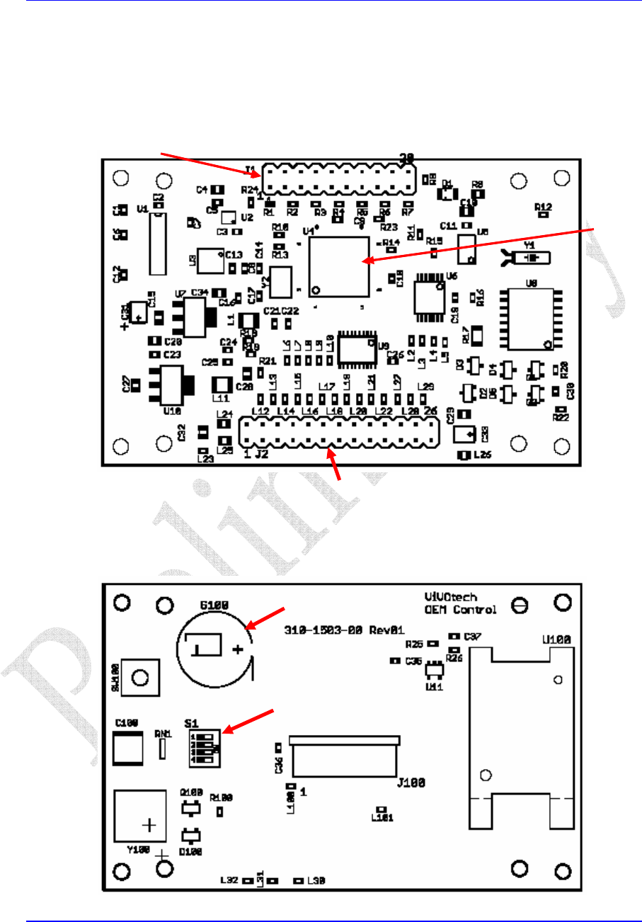
ControlPCA‐FrontView
ControlPCA‐RearView
JTAG Connector (not installed on production units)
ARM
Microcontroller
J2 Connector (see pinouts next page)
Bee
p
e
r
SIM
Socke
t
Antenna
Connecto
r
Configuration
Switches
RTC Batter
y
Document:740‐0005‐00Rev.1.011Proprietary&Confidential

ViVOpay OEM S500 Technical Reference
ControlPCA‐Pinouts
J2–PowerandData
Pin#SignalFunction
1GNDPowersupplygroundinput
2+5VDC5VDCPowersupplyinput
3RS232RETRS‐232Returninput
4+9VDC9VDCpowerinputforHIPowerStripDrive
5TXRS‐232Transmitsignaloutput
6‐RSTExternalResetinput
7RXRS‐232Receivesignalinput
8‐ISPEnableforfirmwaredownloadinput
9GNDPowerSupplyGroundinput
10IT1DInternalTrack1Dataoutput
11STRIPRETStripDriveReturn
12‐IT1CLKInternalTrack1Clockoutput
13TRACK1LOPowerStripDriveTrack1output
14IT2DInternalTrack2Dataoutput
15TRACK2LOPowerStripDriveTrack2output
16‐IT2CLKInternalTrack2Clockoutput
17TRACK2+HIPowerStripDriveTrack2positiveoutput
18‐ICPInternalCardPresentoutput
19TRACK2‐ HIPowerStripDriveTrack2negativeoutput
20CPENABLECardPresentEnable–blocksexternalCPoutput
21XLED1ExternalLED#1Driveoutput
22XLED2ExternalLED#2Driveoutput
23XLED3ExternalLED#3Driveoutput
24XLED4ExternalLED#4Driveoutput
25GNDPowerSupplyGround
26XBUZZExternalBuzzerDriveoutput
J100–AntennaConnector
Pin#SignalFunction
1RF_VCCRF+5VDCoutput
2LED1LED1driveoutput(poweronLED)
3LED2LED2driveoutput
4LED3LED3driveoutput
5LED4LED4driveoutput
6RF_DINRFDatainput
7RF_DOUTRFDataoutput
8RF_SCKRFClockoutput
9RF_SCSRFChipEnableoutput
10RF_RSTRFResetoutput
11VCCLogic+5VDCoutput
12GNDGroundoutput
Document:740‐0005‐00Rev.1.012Proprietary&Confidential
ViVOpay OEM S500 Technical Reference
Document:740‐0005‐00Rev.1.013Proprietary&Confidential
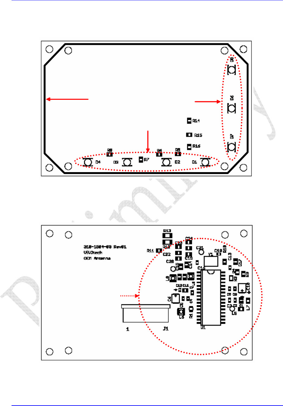
AntennaPCA‐FrontView
AntennaPCA‐RearView
Vertical LEDs
Horizontal LEDs
Antenna
Type A & B Radio
ViVOpay OEM S500 Technical Reference
Document:740‐0005‐00Rev.1.014Proprietary&Confidential
3.0
10.0
47.047.5
3.0
3.5
50.5
76.0
79.0
69.0
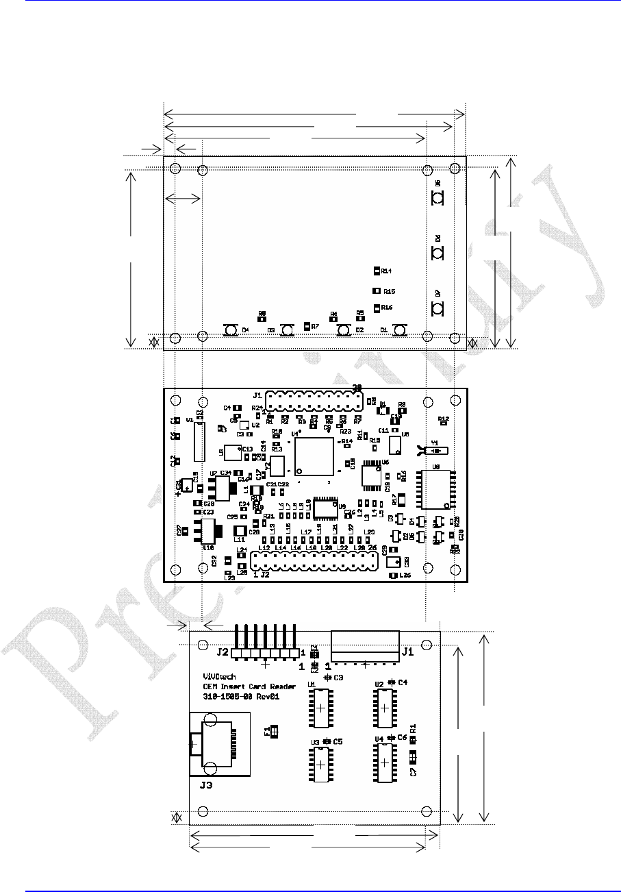
AppendixC‐DimensionsandClearances
(dimensionsinmillimeters)
3.5
65.5
62.0
47.0
3.5
50.5
