Via traffic controlling VIASIS3003 Vehicle speed measurement and display system User Manual VIA SIS
Via traffic controlling GmbH Vehicle speed measurement and display system VIA SIS
Contents
- 1. Manual french
- 2. user manual english
user manual english
Viasis 3003
viasis the mobile and independent
speed indicator system 1
User Manual
Revision 4.1, 8 March 2017
1 This system is based on a development supported with funds of the German ministry of research and technol-
ogy with the project no. 35-250368, with the assistance of the German ‘Fraunhofer Gesellschaft ISE‘
via
traffic
controlling
GmbH
Campusallee 1
D-51379 Leverkusen
Germany
Tel. +49 - (0)2171 - 50 49 30
Fax. +49 - (0)2171- 50 49 50
Email: info@viatraffic.de
Web: http://www.viatraffic.de
TABLE OF CONTENTS
1THE CONCEPT OF VISUAL SPEED INDICATION 1
2GENERAL HINTS AND USED SYMBOLS 2
2.1 Used symbols and text forms 2
3SYSTEM DELIVERY 2
3.1 Unpacking 2
3.2 Supply schedule and equipment 3
4SYSTEM DESCRIPTION 3
5 START-UP WITH THE VIASIS 4
5.1 Mounting and Fixation 4
5.2 Horizontal orientation 5
5.2.1 Leaving traffic 5
5.2.2 Crossing traffic 6
5.3 Viasis MINI text panel 6
5.4 Electrical preparation 7
6VIASIS 3003 SOFTWARE AND DATA 8
6.1 Software installation 8
6.1.1 System requirements for the ViaApp 8
6.1.2 System requirements for viagraph 8
6.1.3 Installation and deinstallation of viagraph 9
6.2 Viasis 3003 data connections 10
6.2.1 Data connection with serial cable 10
6.2.2 Using an USB-RS232 serial adapter 12
6.2.3 USB host interface connection (optional) 13
6.2.3.1 Windows XP and Vista 32 bit USB device driver installation 14
6.2.3.2 Windows Vista 64, 7, 8, 8.1 USB driver installation 16
6.2.3.3 USB driver for Windows 10 18
6.2.4 USB client interface for USB flash storage sticks (optional) 19
6.2.4.1 Parameter transfer from and to the viasis using a USB memory stick 20
6.2.5 Bluetooth modem connection 22
6.2.6 Data connection by GSM radio modem, Email and SMS transfer 24
6.2.7 Manual selection of the viagraph communication (COM) port 26
6.3 Viasis settings and parameter sets 27
6.3.1 Parameter set 28
6.3.2 Time schedule 30
6.3.2.1 Time schedule – Led display 30
6.3.2.2 Time schedule – Operation weekdays 31
6.3.2.3 Time schedule – Daily start and daily stop time 31
6.3.3 Bidirectional detection 32
6.3.4 Menu Speed display options 33
6.3.4.1 Decimal places 33
6.3.4.2 Minimal - and maximal speed displayed 33
6.3.4.3 Threshold blinking LED 34
6.3.4.4 Threshold LED mixed color (Option) 34
6.3.4.5 Threshold LED color change 35
6.3.5 Optimizing display 35
6.3.6 Menu extensions thresholds 35
6.3.6.1 Thresholds LED circle symbols 36
6.3.6.2 Definition of symbols 37
6.3.6.3 LED Warning lights (Option) 38
6.3.6.4 Relays and power MOSFET transistors (optional) 39
6.3.6.5 LED display pages or additional LED fixed text (viasis PLUS or PLUS SMILE) 39
6.3.7 Radar sensitivity 41
6.4 Radio modems 41
6.4.1 Bluetooth modem 41
6.4.1.1 Bluetooth device name 42
6.4.1.2 Pin number 42
6.4.2 GSM/GPRS Modem 43
6.4.2.1 GSM/Email time schedule 43
6.4.2.2 SIM card PIN code 45
6.4.2.3 GPRS configuration 46
6.4.2.4 Configuring the SMTP-Server (Mail server) 47
6.4.2.5 E-mail configuration 49
6.4.2.6 Configure SMS 50
6.4.3 GPS Module (optional) 51
6.4.3.1 GPS position list 52
6.4.3.2 Formatted GPS data output 53
6.4.3.3 GPS raw data (NMEA-183 protocol) 54
6.4.3.4 GPS position fix time 54
6.5 Menu information and Time 55
6.5.1 Protocol 55
6.5.2 Comment – text field 56
6.5.3 System date and time 56
6.5.4 Daylight saving time 57
6.6 Online measurement 57
6.7 Data memory 58
6.7.1 Read measurement data 58
6.7.2 Checking stored measurement data 59
6.8 Test functions 60
6.9 Data evaluation 61
6.10 Viasis PLUS display 62
6.10.1 Viasis PLUS matrix editor – display pages 63
6.10.2 Viasis PLUS matrix editor – bitmaps 64
6.10.3 Bitmap editor 64
6.10.4 Matrix editor menu Tools 65
6.10.5 Permanent text page 65
6.11 Select switch option 66
7TECHNICAL AND PHYSICAL PROPERTIES 67
7.1 Distance range 67
7.2 Measurement angle 68
7.3 Accuracy 68
7.4 Display field and visibility 68
7.5 Display frequency 69
7.6 Power supply and operating time 69
7.6.1 Accumulator version 69
7.6.2 Mains supply 115/230 Volt AC version 69
7.6.3 Viasis with photovoltaic solar support 70
7.7 Operating temperature 70
7.8 Water protection 70
7.9 Radio wave interference 70
8MAINTENANCE 71
8.1 Cleaning the front window pane 71
8.2 Charging and testing the lead acid battery 71
8.3 Changing the battery 72
8.4 Changing the fuse 72
8.5 Serial RS232 interface connector 72
8.6 Trouble shooting 73
8.7 Transport damages 74
8.8 Sending back/transport preparation/disposal 74
9VIASIS 3003 CERTIFICATION, CONFORMITY AND COMPLIANCE 75
9.1 CE-conformity viasis 3003 75
9.2 Viasis 3003 CE compliance and notification 75
9.3 CE-conformity Bluetooth module Laird 730-SA 76
9.4 CE expertise M10 Quectel GSM/GPRS radio module 77
9.5 Viasis 3003 FCC and IC compliance 78
10 ANNEX 79
10.1 Viasis 3003 list of equipment 79
10.2 Technical Specifications viasis 3003 80
10.2.1 Supplementary data – viasis PLUS version 81
10.2.2 Supplementary data – viasis PLUS SMILE version 81
10.2.3 Supplementary data – viasis MINI version 81
10.2.4 Technical Data - Bluetooth modem 82
10.3 Technical data optional components 82
10.3.1 Technical data – Control panel USB 82
10.3.2 Technical data – 115V/230V mains supply 82
10.3.3 Technical data – solar module 83
10.3.4 Technical data – low voltage relays 83
10.3.5 Technical Data – MOSFET power transistors 83
10.3.6 Technical Data - GSM/GPRS radio module and SIM card slot 84
10.3.7 Technical Data – GPS module 85

Page 1 of 85
viasis 3003 user manual
via
traffic
controlling
gmbh
1 The concept of visual speed indication
The visual speed indication and thereby the attempt to influence the driver's speed is quite a
new field in the common road and traffic technology, although the well known traffic lights are
established since decades. Nowadays public authorities start to install luminary speed indication
signs above highways for the same purpose and additionally to manage the traffic flow. Besides
avoiding traffic jams, these systems also shall decrease the drivers speed in order to reduce the
rate of accidents and the heaviness of their consequences.
Our system of a mobile, autonomous and numerical speed indication display fulfils this aim
especially in communal and urban areas, speed limit zones, living areas and in front of schools
and nursery schools.
If we look to the effects of such a speed display, we can state three main effects:
The driver gets the speed of his car publicly
displayed and realizes his „over speeding“.
Therefore the most drivers will be set under psychological pressure and reduce their actual
speed.
The inhabitants of living areas with low speed zones can prove the driving speed of passing
vehicles objectively and as far as local source and target traffic is concerned speak with well
known „fast drivers“ personally.
The communal authorities, often quite helpless with complaints of angry citizens about over
speeding, get an appropriate tool to react. With this tool they delegate in a psychological way
the control function to the concerned citizens.
The police are and was never able to observe the mentioned low speed zones and living areas
in a repressive manner effectively and the expenses for repressive supervision there are not
covered by fines for over speeding drivers. By the way, whether repressive supervision of
speed limitations in living areas is politically suitable is another question.
Up to now the only possibilities of local administrations are road reconstructions to lower
drivers speeding. But such steps are quite costly and under the aspect of the economic situa-
tion of the communities, with low funds not longer practicable.
The systems for visual speed indication however make sense in a wide area covering action.
This wide area covering action just can be run by easy installable and transportable units,
working completely independent for an appropriate time.
Since 1994 via traffic controlling has delivered the speed measurement systems viasis with in-
tegrated display. The viasis 3003 is an actual version of this system with low energy
consumption, integrated battery buffered memory for speed and time data, serial data interface
and a couple of different operating modes.
The possibility not only to measure and to display speed data, but also to collect and herewith
to analyze the collected values statistically grants a control of the effectiveness of the viasis
systems in a certain traffic situation.
In common speed data can be collected (with or without ‘publicly’ displayed speed on the
board) and later on processed statistically permitting the system user profound statements
about the car drivers speeding behavior on a certain road. This makes decisions for or against
further measures, like road reconstruction, repressive speed controls and so on, much easier.
Page 2 of 85
viasis 3003 user manual
via
traffic
controlling
gmbh
2 General hints and used symbols
-Read the manual before you use the viasis system.
-Forward the viasis to other persons only with a manual.
- The viasis housing may only be opened by qualified personal.
- If the viasis housing is opened by the customer, the manufacturer will reject any claims
of warranty and guaranty.
-The manufacturer is not liable for damage caused by improper use or modifications to
the viasis device.
-The following manual is valid for several variants of the viasis 3003 system, like viasis
COMPACT, MINI, PLUS, PLUS SMILE... etc.
2.1 Used symbols and text forms
Safety information, warning of a general danger, evidence
of possible misuse or misconduct with serious conse-
quences.
Danger of hazardous voltages, mortal danger.
Helpful hints, tips and recommendations
Troubleshooting advice
Standard text Normal text instructions
Bold text Highlighting of important text passages
Bold and italic text References to program texts, symbols and functions
Information text: Program cited text passages
3 System delivery
3.1 Unpacking
Unpack the delivered parcel with the viasis system immediately. From the outside
invisible transport damages (see also chapter 8.7) can be enforced only a few days
against the hauler.
Please retain the original packaging, because if the equipment is sent back it should be packed
only in the original packaging. We will gladly accept send back packing material, if it is not
possible for you to store it due to a lack of storage space.
Small parts and cables will be packed in the battery box. Please check the box when unpacking
the system.

Page 3 of 85
viasis 3003 user manual
via
traffic
controlling
gmbh
3.2 Supply schedule and equipment
To the delivery containment of our systems belong following components:
1. Viasis speed measurement and display system for vehicle speeding
2. Fuses, 2 pieces (one spare piece)
3. Sliding nuts M6, 4 pieces for standard C-profile rails
4. Serial interface cable, about 4 meters long
5. CDROM with manual, terminal and data evaluation software
6. Option USB – USB cable and USB flash storage stick
Measured and stored data from a viasis can be read with a personal computer, a notebook or
laptop with serial RS232 interface and the delivered viagraph software working with Windows
XP/Vista/7/8 and Windows 10.
If you want to use the serial RS232 interface of the viasis, but your computer offers only a
USB interface, you can obtain a serial USB-RS232 adapter from us, see annex chapter 10.1 –
list of viasis equipment.
4 System description
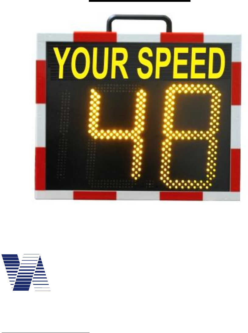
The viasis 3003 measures and displays vehicle speeds of one drive lane and direction. The
viasis is an accumulator supplied, mobile measurement system, particularly designed for lowest
power consumption. Measured speeds are shown on a 300 mm high, seven-segment LED
board with 2 ½ digits. The used high brightness LED are mounted behind a rigid “phantom
light” mask to avoid seemingly display of speeds due to sun or vehicle light reflection.
Alternating with the numeric speed display, several warning and speed limit sign symbols with
a circle diameter of 300 mm can be shown. Optionally the viasis 3003 is equipped with two
LED display colors, with the possibility to change the displayed color according the compari-
son result of measured vehicle speed and a set speed threshold.
Measured vehicle speeds are stored in the viasis, marked with time and date of the measure-
ment and can be later transferred by means of a serial communication interface like RS232,
USB or other optional radio data interfaces, like Bluetooth or GSM/GPRS mobile phone. The
viasis can be set to measure data of both driving directions of a two lane road and to store the
data for later evaluation.
Typically the viasis measures periodically every 1.5 seconds and shows the result. In case of a
new vehicle measurement the display is refreshed after 1.5 seconds, otherwise the display is
hold for maximal 3 seconds.
The measuring unit consists of a continuous wave „Doppler Radar“, a permanent sending high
frequency radio wave emitting and receiving unit, whose antenna is not visible through the
front window pane. This measuring unit delivers the received signals by an amplifier and digital
processing electronic to a microprocessor unit that evaluates the signals.
The viasis 3003 is delivered with numerous options, see also chapter 6.3.6, in several variants
like viasis COMPACT, MINI, PLUS, PLUS SMILE, etc. for various different applications.
Page 4 of 85
viasis 3003 user manual
via
traffic
controlling
gmbh
5 Start-up with the viasis
5.1 Mounting and Fixation
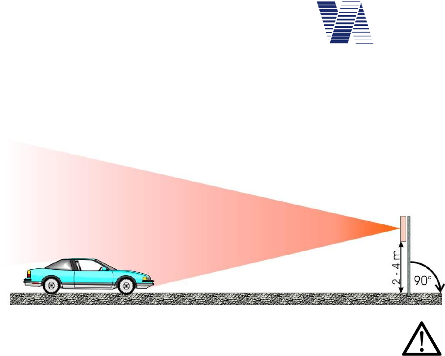
The viasis must be mounted orthogonal to the road and stable in a height of 2 meters till 4
meters below the housing edge, see . First mount the system and finally insert the battery.
Illustration 1: Vertical orientation
Following items must be observed:
Another mounting height or a strong inclination of the housing (exceeding 90° ± 8°) may
influence the distance range of the vehicle detection and the accuracy of the displayed speed
values.
The radar detector in the viasis needs „free sight“ on the measured vehicles. Avoid a mount-
ing behind trees, poles, high parking vehicles and so on.
The system shall not be used in the range of road turns and bends. Otherwise too low meas-
ured speeds can be the result.
For the fixation of the viasis at pole clamps use the delivered M6 slide nuts. Pull two slide nuts
in each C-profile rail at the backside of the viasis housing. With 2 x 2 M6 screws (not deliv-
ered) the pole clamp is fixed at the slide nuts, respectively the profile rails.
We offer a solid and lockable pole fixation kit for the viasis, see annex list of equipment chap-
ter 10.1 and our website www.viatraffic.de.
If there is no possibility to mount to already existing poles or if the system is used only in short
mobile campaigns, we also deliver a mobile tripod, see annex list of equipment, with a tele-
scope pole. If you use a mobile tripod you should be aware that you need to guard the system!
Page 5 of 85
viasis 3003 user manual
via
traffic
controlling
gmbh
5.2 Horizontal orientation
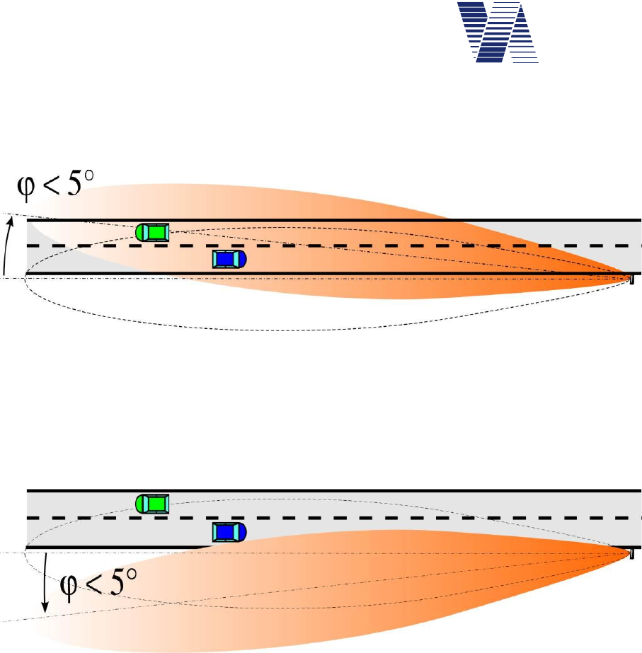
Direct the system horizontally through turning the system board around the mounting pole.
The ideal orientation to reach a maximum distance range depends on the local circumstances.
Illustration 2: viasis display directed to the road with a measurement angle = 5°
For the first the system should be straightened parallel the roadway and can be turned until a
measurement angle of 5 to the lane (see illustration 2) until the vehicles are detected from
the unit at the maximum distance range.
If leaving traffic reduces the distance range remarkably, the system board can also be turned
away from the roadway up to a measurement angle of 5 (see illustration 3).
Illustration 3: viasis display directed away from the road with a measurement angle = 5°
A measurement angle of more than 5 lead to the display of too small speed values and may
cause measurement errors outside the specified accuracy.
5.2.1 Leaving traffic
The system is adjusted to approaching objects (toward the front side of the board). Leaving
objects are also detected but filtered out.
Practically also leaving traffic can cause a distance range reduction. Because the object with
the highest reflection amplitude, under certain circumstances the leaving traffic can be domi-
nant for a short time and therefore „blinding“ the detector, although this detection is filtered
out and is not displayed.
If necessary the display board can be turned away from the leaving traffic lane within certain
limits to get an undisturbed detection, see also chapter 5.2.
Page 6 of 85
viasis 3003 user manual
via
traffic
controlling
gmbh
5.2.2 Crossing traffic
Diagonal crossing traffic passing the radar beam can lead to a disturbing speed value display.
By following measures you can reduce the detection distance range of the radar:
Decline the viasis housing vertically (see illustration 1) up to 8° towards ground.
Reduce the sensitivity of the radar receiver, see also chapter 6.3.7.
If both measures show no satisfying results there is nothing to do as to get away from the
crossing traffic.
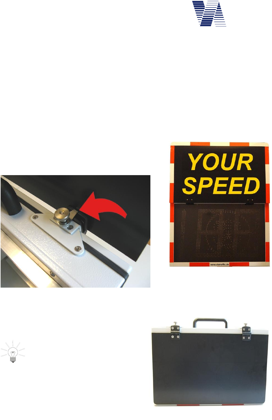
5.3 Viasis MINI text panel
During the mounting the fixed text of the viasis MINI is folded in the visible upright position
by means of a movable flap board, see illustration 5.
If the flap board is open and upright both hinges are
fixed with rotatable hooks in this position, see also red
arrow in illustration 4.
The fixation hook is hanged into the slot
at the hinge and secured by tightening
the knurled nut above.
The closed flap board is attached to the housing
during transport by two hidden magnetic holders.
Attention: Don’t forget to tighten the
knurled nuts before you transport the
viasis MINI. Otherwise they may get
loose and lost together with the hooks.
Illustration 4: Fixation hook
Illustration 5: Open flap board
Illustration 6: viasis MINI flap board closed
Page 7 of 85
viasis 3003 user manual
via
traffic
controlling
gmbh
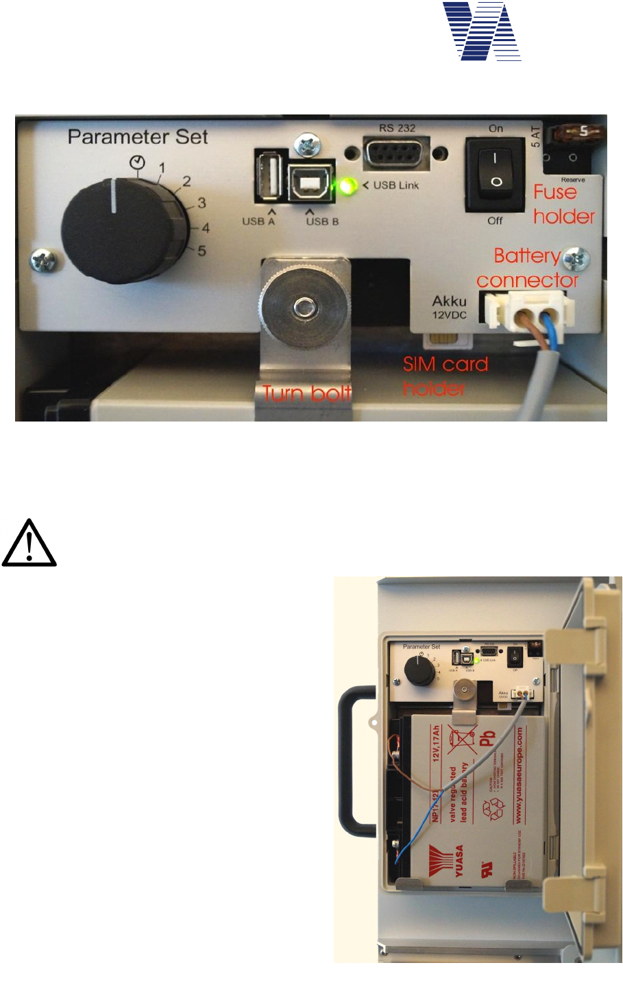
5.4 Electrical preparation
Untighten the knurled nut of the battery attachment,
turn the fixation bolt aside and insert the battery into the box. Secure the battery in its position
with the turn bolt and by tightening the knurled nut, see also illustration 7 and illustration 8.
Warning: Hold the battery always and as long as possible with both hands.
Secure the battery immediately after insertion with the turn bolt. Falling down
batteries can cause severe injuries.
Plug the connector of the battery cable into the
socket of the control panel labelled Akku
12VDC, see also illustration 7. The 5 ampere
system fuse should already be placed into the
fuse holder on the control panel. Press the
On/Off toggle switch (labeled 1/0) in position 1
so that the viasis is turned on.
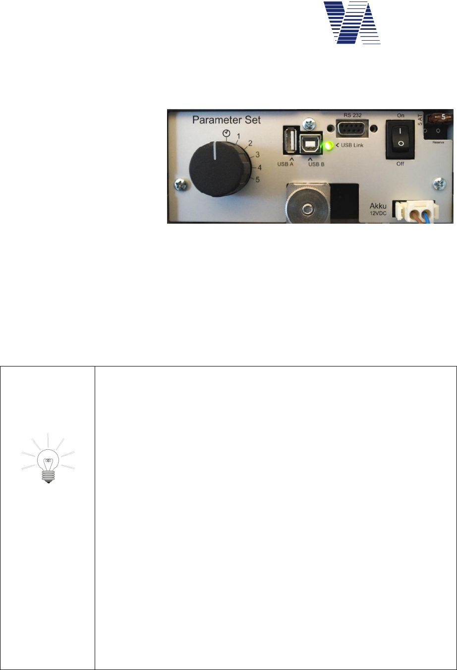
Illustration 7 shows the viasis control panel in
the open battery box with USB connectors. Only
if optional USB interfaces are equipped the
green function control LED (USB-Link) can be
found, which is lit during the viasis power on
initialization time.
Directly after power on, during initialization the
viasis shows “188” on the numeric LED display
for about 3 seconds. Further 3 seconds the bat-
tery voltage is shown, for example 13.2 repre-
senting a viasis supply voltage of 13.2 Volt.
Hereafter the system is ready for operation and
the display is empty until the first vehicle is de-
tected.
Illustration 7: viasis control panel
Illustration 8: Battery box and control panel

Page 8 of 85
viasis 3003 user manual
via
traffic
controlling
gmbh
Later in cyclic offline measurement mode the green function control LED is lit during the radar
measurement, what means typically all 1,5 seconds for 50 to 100 milliseconds.
The lead acid accumulator batteries are only partly charged after delivery. Before you start a
longer measurement campaign charge the battery to its full capacity. Otherwise the operating
time will be reduced. In order to power the system on, the battery voltage level must be above
11,3 Volt.
Attention: Wait 5 seconds or more to repower the viasis after you powered it
off before. Otherwise malfunctions and error messages of viasis components,
which did not reach the off state completely, can be caused.
Take care not to press or damage the battery wires, when you close the box cover.
The battery box can be protected against unauthorized access with a padlock through the fore-
seen holes in battery box body and cover, see illustration 8.
The Viasis is configured for permanent operation after delivery (see also chapter 6.3) and is
ready for operation.
6 Viasis 3003 software and Data
6.1 Software installation
6.1.1 System requirements for the ViaApp
For smartphones and tablets with Android operating system version 4.0 and higher the ViaApp
can be installed for the communication with the viasis by the Bluetooth interface. The file
viatraffic_app_1_2_3.apk can be found in the folder /Tools/via_app on the delivered CD-
ROM. After transfer of the apk file to your smartphone/tablet by Bluetooth/USB or as an
email attachment the installation procedure is started in common automatically.
After the installation of the ViaApp an update to the newest version is also started automatical-
ly in case a connection to the Internet exists.
With the ViaApp parameters of the viasis can be set, measurement data can be downloaded
and forwarded as an email file attachment.
ViaApp was tested with several devices, but due to the large number of devices on the market
no right to the proper functioning of ViaApp with each individual system can be granted. A list
with smartphone/tablet devices tested by via traffic with the ViaApp can be found in the folder
/Tools/via_app on the delivered CD-ROM.
6.1.2 System requirements for viagraph
For the successful installation and later operation of the delivered data evaluation program
viagraph on your computer following minimum requirements must be fulfilled:
Windows XP/Vista/7/8 and 10 in standard installation
280 MB free hard disk space
Monitor resolution of minimal 1024 x 768 pixel
CD/DVD drive
Page 9 of 85
viasis 3003 user manual
via
traffic
controlling
gmbh
The software package viagraph is delivered on CD-ROM. For notebooks without
CD-ROM/DVD drive you may copy the CD-ROM to an USB flash disk and start
the software installation from the USB flash disk hereafter.
6.1.3 Installation and deinstallation of viagraph
After insertion of the delivered CD-ROM in the CD-ROM drive of your computer the installa-
tion program is in common started automatically. If the „auto run“ function of your CD-ROM
drive is deactivated, start the installation program autostart.exe located on the CD-ROM root
folder with the Windows task bar start menu start – execute.
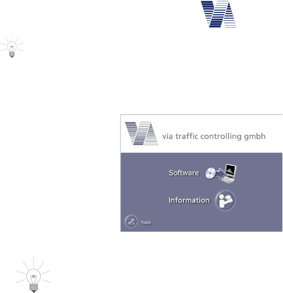
With a mouse click select Software in
the dialogue page shown in illustra-
tion 9.
In the following page click on the line
viagraph and the installation of the
software package is started.
The software package viagraph al-
lows the evaluation of measurement
data of Via devices. Further a com-
munication program for the data
transfer between the viasis and your
computer is an integral part of the
software.
For the first installation you need administrator user
rights!
During the installation select the option field „Installa-
tion for all users“.
The later user needs all access rights for the installation
folder.
Depending on the Windows version the installation of the Microsoft .NET run time module
including an appropriate language support is done automatically.
For the correct deinstallation click the Windows start button in the task bar and then Start –
system control – software, respectively Start –control panel – programs, depending on your
Windows version and select viagraph for the deinstallation in the program list.
Illustration 9: Software installation
Page 10 of 85
viasis 3003 user manual
via
traffic
controlling
gmbh
6.2 Viasis 3003 data connections
The viasis 3003 is always equipped with a serial RS232 and a Bluetooth interface. Depending
on the viasis variant other interface options vary. It is possible to equip the viasis additionally
with USB host interface for computer connections and USB client interface for memory
sticks. Further a GSM/GPRS radio modem interface with GPS function can be installed.
Attention: At the same time only one data connection shall be active. Oth-
erwise an existing connection might be interrupted and the new connection
may not work properly.
6.2.1 Data connection with serial cable
Connect the delivered RS232 interface cable to a serial RS232 socket of your computer and to
the viasis RS232 interface socket on the control panel in the battery box, see also illustration 7.
Connect the battery to the viasis and power it by the On/Off switch, if not done already.
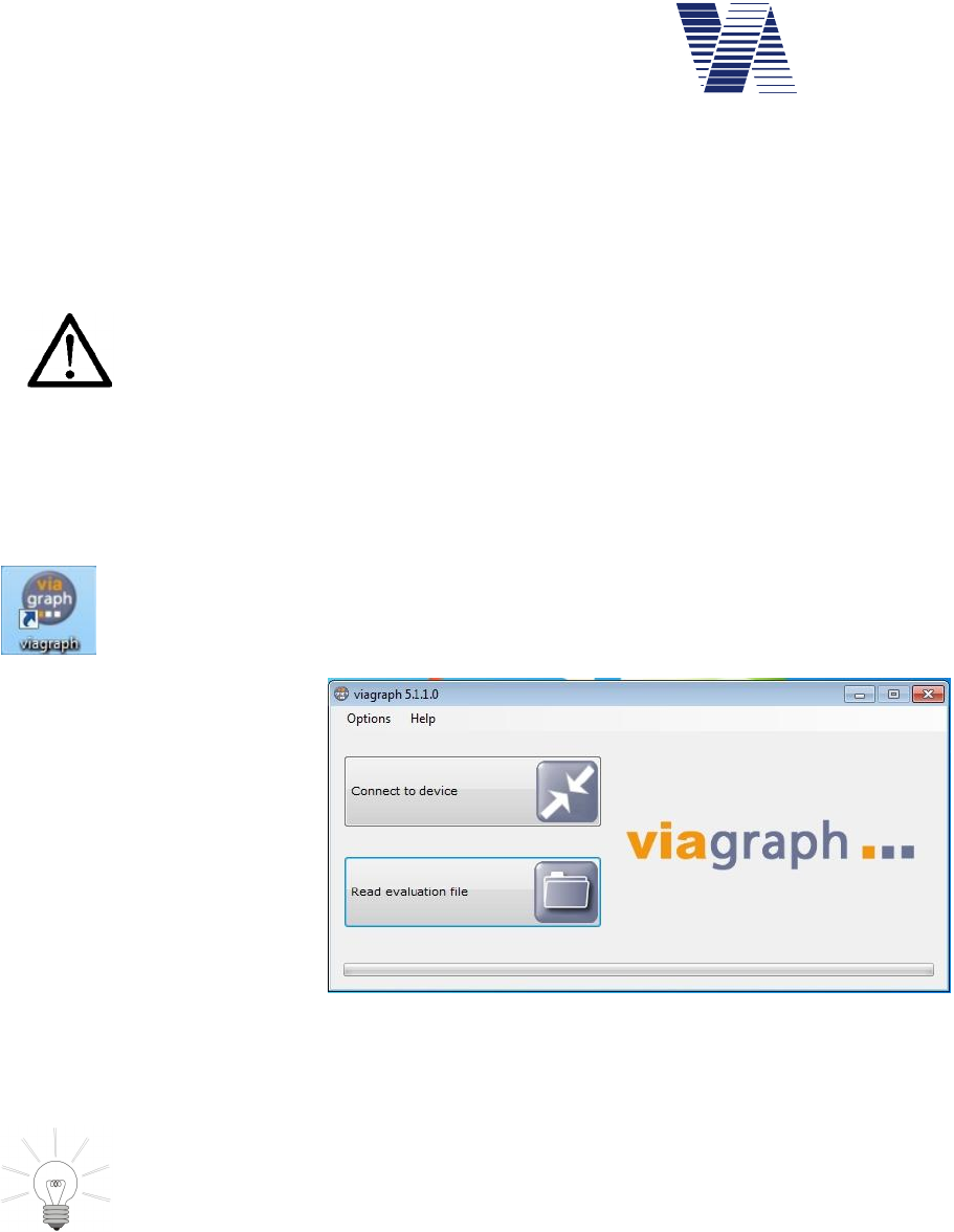
Start the viagraph program with a mouse double click on the viagraph icon placed
on your Windows desktop after installation. After viagraph has started you may
choose the preferred program language version from the offered list in the menu
Options – Language.
In the following dialogue click
the on Connect to device, see
illustration 10.
The empty viagraph main
window appears, see illustra-
tion 11.
The program scans all serial interface ports of the computer for known devices and modems.
and will choose automatically the first serial port with a connected via device.
In case of several connected via devices or modems by different serial interface
ports (Bluetooth, USB or GSM) it may happen that viagraph does not select the
device or modem to which you wish to connect. In this case please refer to chap-
ter 6.2.7.
Illustration 10: Program selection
Page 11 of 85
viasis 3003 user manual
via
traffic
controlling
gmbh
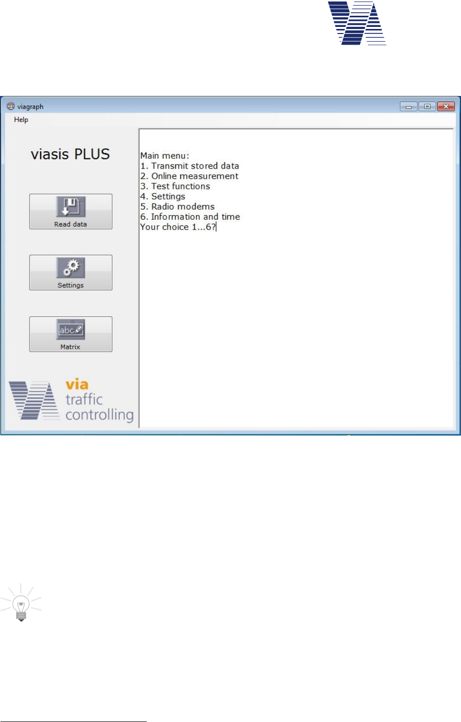
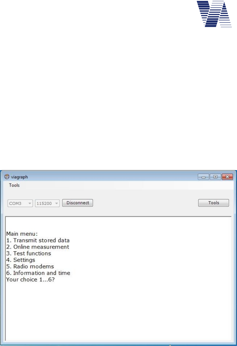
If the connection is established successfully, the viasis main menu appears in the white terminal
input/output area of the viagraph window, see illustration 11.
Illustration 11: Viagraph connection window with viasis main menu in the terminal
Top left the type of the found viasis system is shown, e. g. viasis, viasis PLUS, viasis PLUS
SMILE, etc. Depending on the viasis type and equipment appears one or more buttons below.
The buttons Read data and Settings appear always for viasis 3003 systems, the button Matrix
is only shown for viasis 3003 PLUS devices.
By a click in the input/output terminal area (white background) you may make insertions by
your computers keyboard to the viasis menu system directly. Menus, messages and responses
from the viasis are displayed then in the terminal area.
The more comfortable way to change viasis parameters is to click the Settings
button, respectively the Matrix button if you want to change parameters and text
pages of a viasis PLUS.
In case you connected to a viasis with GSM/SMS/Email function by serial RS232 cable, an
Email or SMS transfer may occur while you are connected. The text “Send Email/SMS...”
may appear in you terminal window. Please make no insertions further on, respectively do not
click any buttons in viagraph until you see the transfer closing message “Email/SMS ok”.
More information about viagraph you will find in its online help1 menu Help – Manual.
1 To read the viagraph online manual requires an installed Adobe Acrobat Reader Version 3.0 or higher. You
may obtain it from Adobe by the Internet on the website http://www.adobe.com/
Page 12 of 85
viasis 3003 user manual
via
traffic
controlling
gmbh
6.2.2 Using an USB-RS232 serial adapter
Connect the USB-RS232 serial adapter to a free USB port of your computer. Depending on
which Windows operating system you use, the presence of the USB-RS232 adapter is recog-
nized by Windows as soon the adapter is plugged in. A message like “new hardware detected”
is shown and you will be asked to install a driver for the USB device.
For the installation of the USB device driver please refer to the instructions of the USB adapt-
er package. The adapter package in common includes a CD-ROM with the needed device
drivers and installation instructions.
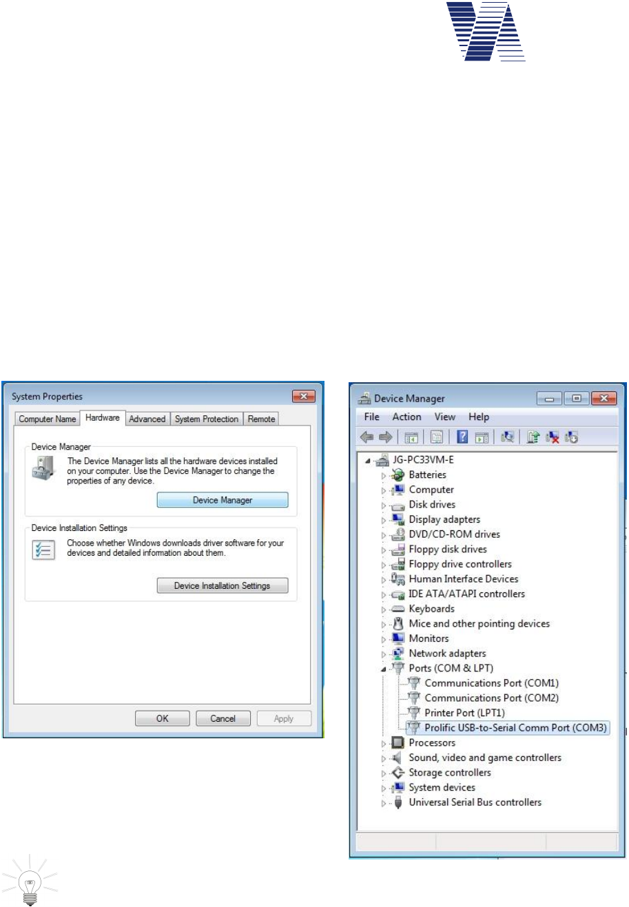
If the USB-RS232 interface adapter has been correctly installed as a serial COM port, you may
check it in the windows “Device manager”. Unfortunately the way to, respectively the place-
ment of the device manager varies with the different Windows operation systems. In the
Windows 7 desktop click “„Start – Control Panel – System and Security – Device Manag-
er”. Under Windows XP/Vista the “Device manager” is found in the “System properties”
register “Hardware”, see illustration 12.
Open the „Device manager“ and expand the line
„Ports (COM & LPT). The USB-RS232 adapter
must be listed here below.
Hint: In case you use several different
USB sockets to connect the adapter
you may have to reinstall the USB driver.
Now connect the USB-RS232 adapter to the viasis with the delivered RS232 cable, connect
the battery and proceed as described in chapter 6.2.1.
Illustration 12: System properties
Illustration 13: Device Manager
Page 13 of 85
viasis 3003 user manual
via
traffic
controlling
gmbh
6.2.3 USB host interface connection (optional)
If the viasis 3003 is delivered with USB interfaces the USB sockets USB-A (for memory
sticks) and USB-B (PC connection) are placed on the control panel, located in the battery box,
see also illustration 14.
Before you can establish a USB
data connection with your com-
puter you need to install an
USB device driver, see chapters
6.2.3.1, 6.2.3.2 and 6.2.3.3.
The used driver is a Windows
standard interface driver
“usbser.sys” for a so called CDC
(Communication Device Class)
device, which also sets up a virtual COM port (a virtual serial interface), which can be used by
terminal programs.
The USB driver installation should preferably done with administrator user rights.
The USB-Link LED is lit continuously as soon you plugged the cable in the viasis USB-B
socket and a USB-A socket of your computer.
For a proper operation be aware of:
-The viasis cannot be supplied by the USB interface, therefore the viasis
must by powered e. g. by a charged 12Volt battery for establishing a
data connection.
-The internal viasis microcontroller has physically only one USB
host/client interface, which can be configured either as a host or client
USB interface, so either a PC connection can be made or else a USB
memory stick shall be plugged in, but both will not work the same
time.
-During power on initialization (USB-Link LED lit) no USB connec-
tion shall exist or shall be established. As soon the viasis completed
initialization and the LED begins to flash shortly make a USB connec-
tion.
-In case the USB connection to your computer is made by means of a
USB hub, the data transmission speed can be reduced remarkably.
-Always close the data connection before you unplug the cable. In
viagraph this is done by closing the main window, e. g. in the terminal
program HyperTerminal exists a connect/disconnect button to sepa-
rate and close the connection. Otherwise the programs may hang up or
do not recognize a reconnected viasis.
Illustration 14: Control panel with USB sockets
Page 14 of 85
viasis 3003 user manual
via
traffic
controlling
gmbh
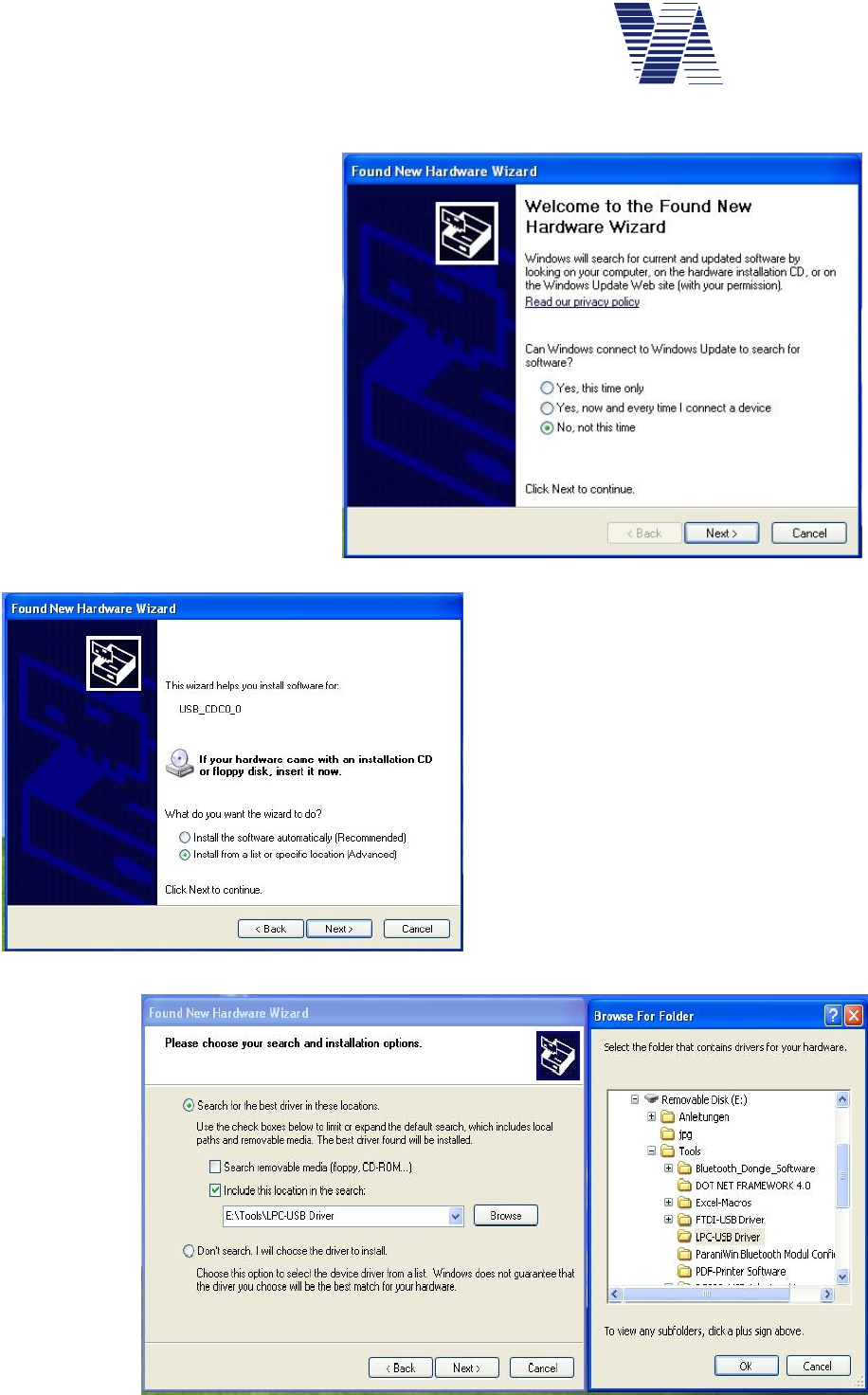
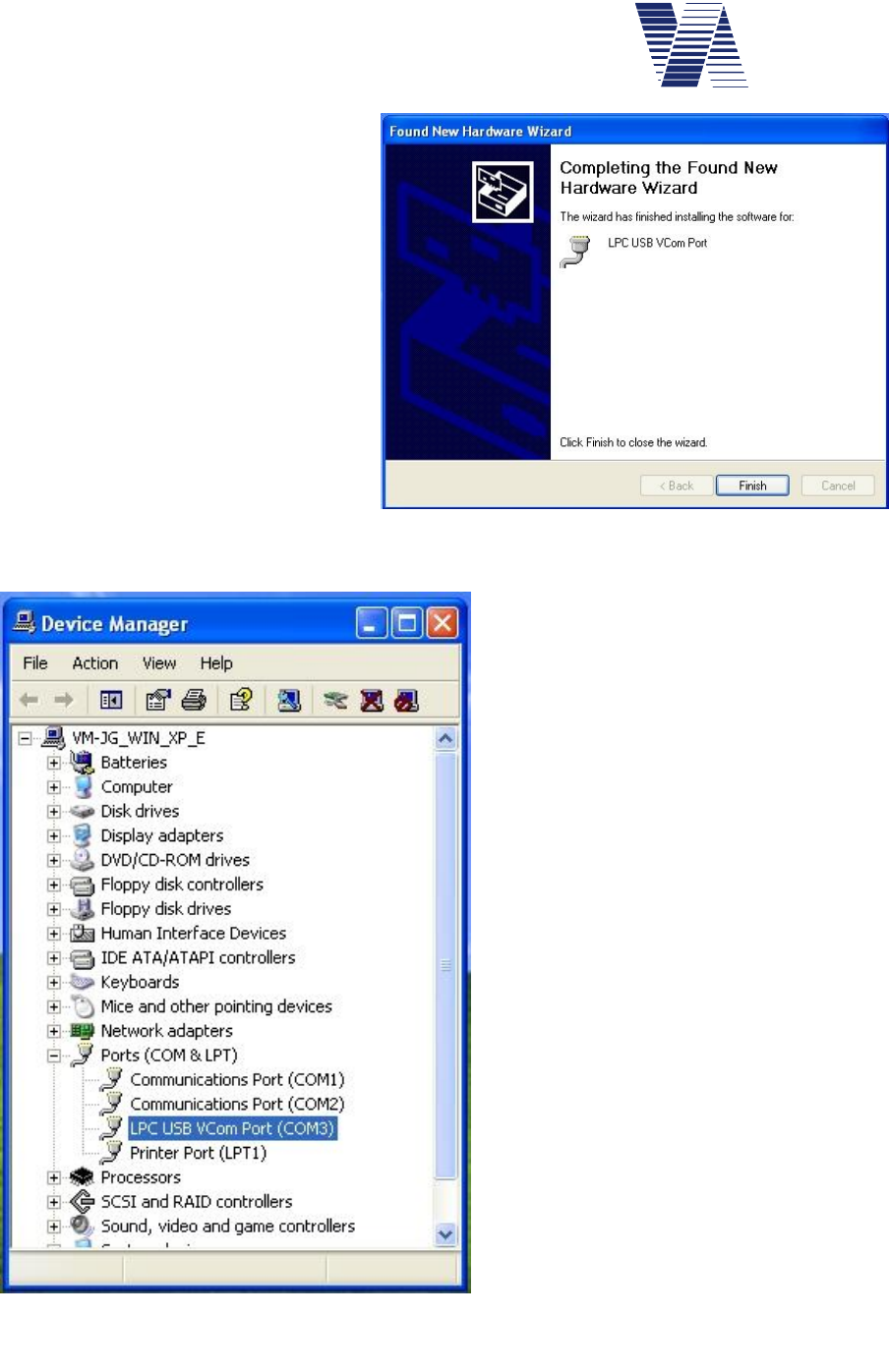
6.2.3.1 Windows XP and Vista 32 bit USB device driver installation
The following installation dialogue
is shown here for Windows XP and
differs minimal for Windows Vista
32 bit.
If the USB cable connection has
been made the Windows Found
New Hardware Wizard appears
automatically.
A search on the Windows Update
website is time consuming and not
needed, so click No, not this time
and Next, see picture right aside.
Enter the delivered „Via“ CD-
ROM in the DVD/CD-ROM drive
of your computer.
Choose Install from a list .... and click
Next, as shown in illustration 16.
In the next window below activate
Search for the best driver ... and click the
option field Include this location in the
search, see illustration 17.
Click on the Browse button and search on
the CD-ROM drive first the Tools and
then the LPC-USB Driver folder.
Click the OK button and the driver instal-
lation will start.
Illustration 15
Illustration 16
Illustration 17
Page 15 of 85
viasis 3003 user manual
via
traffic
controlling
gmbh
The „...Windows Logo Test...“ mes-
sage confirm with a mouse click on
the Continue Anyway button.
Depending on your Windows user
rights, respectively the Windows set-
tings regarding device driver
installations, the installation may fail.
In such a case contact your system
administrator, respectively repeat the
installation with administrator rights.
After a succesful USB driver
installation you should also find it in
the Windows Device manager (Start –
Control Panel –Performance and
Maintenance – System – Hardware –
Device manager), see illustration 19, in
the expanded Ports (COM & LPT) line
the LPC USB Vcom Port.
The serial USB interface of the viasis can
be used now with viagraph or another ter-
minal program and a COM port to the
viasis 3003 can be opened, see also chap-
ter 6.2.1.
Illustration 18: USB driver installation completed
Illustration 19: Device manager with virtual COM
port
Page 16 of 85
viasis 3003 user manual
via
traffic
controlling
gmbh
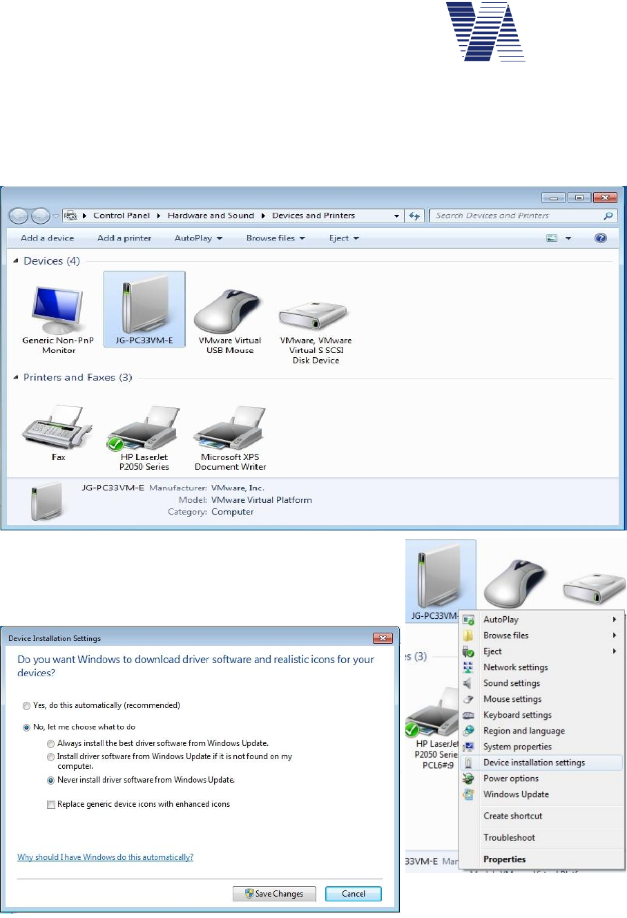
6.2.3.2 Windows Vista 64, 7, 8, 8.1 USB driver installation
In order to avoid long and unnecessary waiting time switch the automatic search for driver on
the Windows update server off. The needed driver resp. the driver information cannot be found
there. To switch the automatic driver search off open the Devices and Printers window, see
illustration 21, either by the Windows Start menu or the Control Panel.
Illustration 21: Windows Devices and Printers
Click with the right mouse button on the symbol of your
computer in Devices and Printers. In the displayed menu
selection choose Device installation settings.
Activate Never install driver software from Windows Update and click on the Save Changes
button, see illustration 22 above. After the USB driver installation you may restore the old
installation settings in this window.
Illustration 20
Illustration 22
Page 17 of 85
viasis 3003 user manual
via
traffic
controlling
gmbh
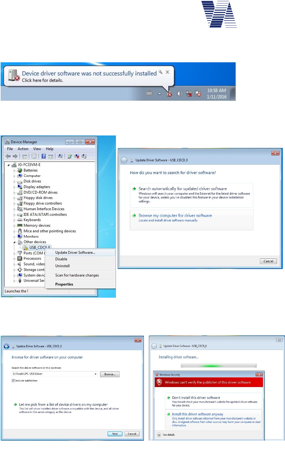
Now connect the powered viasis and your computer with the delivered cable. Plug the USB-B
connector in the viasis operator panel USB-B socket, see also illustration 14 and the USB-A
connector in your computer socket. The message Device driver ... not ... installed appears.
Illustration 23
Open the Device Manager, e. g. with the Windows menu Start – Control Panel – System and
Security – System – Device Manager. In the device class Other devices you will see the de-
vice USB_CDC0_0. Make a right mouse click to USB_CDC0_0 and select Update driver
Software in the displayed menu, see illustration 25.
Choose Browse my computer for driver software, see
illustration 24. Enter the delivered CDROM in your
CD/DVD drive. In the following dialogue click the
Browse button and navigate to the folder
\Tools\LPC-USB Driver on the delivered CDROM, see illustration 26.
Illustration 24: Driver search
Illustration 25: Driver update
Illustration 26: Driver file folder Illustration 27: Driver verification
Page 18 of 85
viasis 3003 user manual
via
traffic
controlling
gmbh
In the Windows Security message window click on Install this driver software anyway, see
illustration 27.
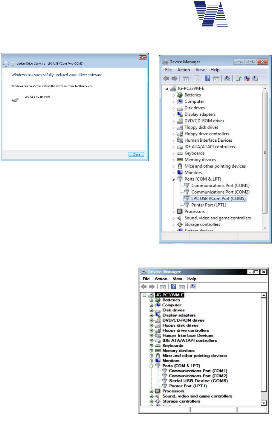
Click the Close button as soon the message Win-
dows successfully updated your driver software is
shown, see illustration 28.
The device manager will list in Ports (COM&LPT)
the USB device driver LPC USB Vcom Port, see
illustration 29.
By means of the established virtual serial COM port
as a device interface viagraph and other terminal
software can communicate now with the viasis.
6.2.3.3 USB driver for Windows 10
Under Windows 10 in case a USB CDC
(communication device class) system is con-
nected the first time the Windows integral
standard driver file “usbser.sys” is installed
automatically without the need to provide
additional driver information files (*.inf) or
catalogue files (*.cat).
During the USB cable connection between
viasis and your computer with a Windows 10
operating system a virtual COM Port Serial
USB device (COMn) is visible in the Device
Manager in Ports (COM & LPT).
Illustration 28 : Installation completed
Illustration 29: LPC USB Vcom Port
Illustration 30: Windows 10 serial USB device

Page 19 of 85
viasis 3003 user manual
via
traffic
controlling
gmbh
6.2.4 USB client interface for USB flash storage sticks (optional)
USB flash drives or memory sticks can be plugged in the USB-A socket of the control panel
located in the battery box, see also illustration 14.
Following points shall be recognized for a trouble free operation:
-As long as a USB memory stick is plugged into the viasis control
panel no other data connection between the viasis and a computer,
particularly no USB host connection shall be established.
-The USB interfaces of the control panel fulfills the USB 2.0 specifi-
cation. According a USB client interface need to deliver maximal 100
mA for „low power“ mass storage devices.
-The USB memory stick shall only be plugged for the time of a data
transfer and be removed afterwards. As long as the USB memory
stick is plugged in the viasis does operate in measurement mode
After connection of a USB memory stick the viasis executes in sequence following tasks:
-If not found in the USB stick root directory a folder “VIASIS” is created
-Download of stored measurement data in a file (*.VTF) in the “VIASIS” folder. Stored
measurement data in the viasis are deleted afterwards.
-If a firmware file1 (*.BIN) is found in the “VIASIS” folder it is loaded and a firmware up-
date is started.
-In case a parameter file (file extension *.PAR) is found in the “VIASIS” folder it is loaded
into the viasis and the viasis is reconfigured.
-If not already created before a new the log file “USBINFO.TXT” is placed in the
“VIASIS” folder. All up- and download actions are logged herein.
A text entry example for writing a measurement data file in “USBINFO.TXT” follows:
Viasis 3003 - Version 4.12, 15SC4321
Date: 15.09.2015, Time: 14:14:46
Write SC_15SC4321_150915_001.VTF ok
Also if the viasis measurement data store is empty a file with the extension *.VTF will be cre-
ated. This file includes the current parameter and the event protocol of the viasis.
The meaning of the USB-Link LED on the operator panel when using an USB memory stick
shows the following table:
Green USB-Link LED USB-Stick LED
2
Status
Permanent lit Permanent lit USB stick is initialized.
Diminishes quickly Diminishes quickly Data are transferred, read and written
Slowly Blinking, 0,5s on
and 0,5s off
off Remove the USB stick, all actions done
by the viasis
1 viasis microcontroller program software
2 if exists
Page 20 of 85
viasis 3003 user manual
via
traffic
controlling
gmbh
For the operation of USB memory sticks at your computer in common no customer
installed device driver is needed, because they can be operated with already installed
Windows standard mass storage device drivers
6.2.4.1 Parameter transfer from and to the viasis using a USB memory stick
The viagraph software allows it to modify viasis settings offline and to store the settings in a
parameter file on a USB stick. When the USB stick is plugged the next time in the viasis the
parameter settings are read and the viasis is reconfigured.
With viagraph created parameter files (file ending *.par) are named with the unique serial num-
ber of the viasis (e. g. 15SC4321.PAR) and are only loaded by the viasis with the same serial
number. So several parameter files can be placed in the “VIASIS” folder of a USB memory
stick for several viasis systems.
The precondition for the modification of the viasis system parameter settings offline is that the
viasis type and version is already known to the viagraph program:
Either you connect the viasis directly to your computer and click on the “Settings“ button in
viagraph, see also chapters 6.2.1, 6.2.3 and 6.2.5, resp. illustration 10 and illustration 11.
Else plug an USB stick into the powered viasis to retrieve a VTF file, see also chapter 6.2.4.
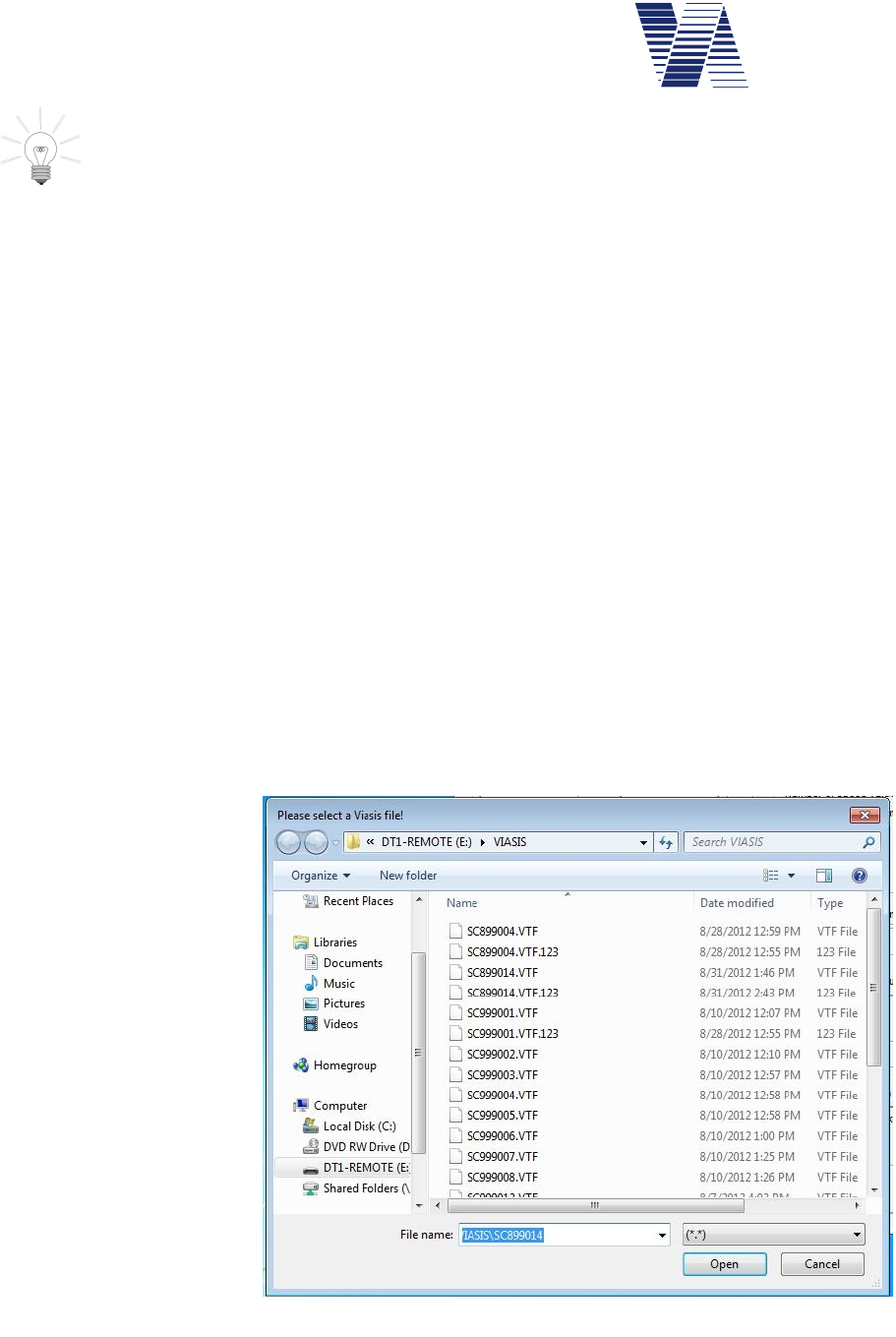
Afterwards plug the USB Sticks into an USB port of your computer and „evaluate“ the VTF
file with the viagraph software.
The actions of first possibility are already described before in the manual. For the second pos-
sibility start viagraph by the viagraph button on your desktop. In the viagraph program
selection, see also illustration 10, choose Read evaluation file.
Plug in the USB stick and
open the VTF file in the
VIASIS folder of the
viasis system, whose set-
ting you want to modify
later, see illustration 31.
The VTF file probably
may contains no measure
data, therefore you are
prompted with a viagraph
error message, which you
can ignore.
Close and reopen
viagraph.
Illustration 31: Open viasis VTF file to retrieve the settings
Page 21 of 85
viasis 3003 user manual
via
traffic
controlling
gmbh
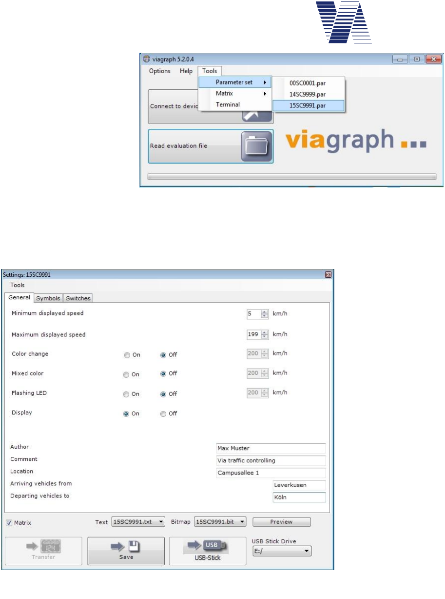
In the viagraph start win-
dow select the menu Tools
and further Parameter set,
see illustration 32. From
the here given list of pa-
rameter files (*.par) select
the viasis with the serial
number, whose settings
you want to modify.
The screen with the viasis
settings is shown then, with
several tabs depending on
the viasis type, see illustration 33.
Here you can make the needed parameter changes offline, see also chapter 6.3 following.
With the buttons
Save and USB-Stick
you may save the
parameter settings
for later use on the
computer hard disk
drive or the changed
parameters directly
to the USB stick.
Before you click the
USB Stick button,
select the correct
USB Stick Drive
letter.
If you plug-in the
USB stick with the
changed parameters
at your viasis, the
parameter file is au-
tomatically read and
the viasis reconfig-
ured.
Only if you selected the parameter file of a viasis PLUS, see illustration 32, appears the check
box Matrix in the settings window, see also illustration 33.
Is the option Matrix activated you can save text pages and bitmaps (see also chapters 6.10.1
and 6.10.2), which are stored in files on the hard disk, together with the parameter settings in a
single parameter file on the USB stick for a further transfer to a viasis PLUS. With the drop
down selections Text and Bitmap you can choose the files.
Illustration 32: viasis parameter file selection
Illustration 33: viasis settings
Page 22 of 85
viasis 3003 user manual
via
traffic
controlling
gmbh
6.2.5 Bluetooth modem connection
Check whether you computer is equipped with a Bluetooth radio interface ready for operation.
If not you may obtain e. g. a USB Bluetooth dongle and install the device driver and operating
software delivered by the manufacturer.
Depending on the operating system of your computer and the installed Bluetooth interface,
either internal or external modem, the way to establish a Bluetooth data connection will vary.
Therefore for internal Bluetooth modems please check the online help system of your comput-
er and for external Bluetooth modems solution check the installation and operation manual of
the manufacturer, delivered with the modem.
If standard (generic) Windows Bluetooth interface drivers are used for the Bluetooth modem
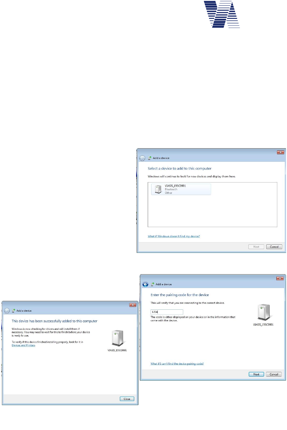
operation, the initial configuration of the Bluetooth connection is shown for Windows 7 below:
-Open Devices and Printers by the
Windows Start menu or the Control
Panel. In the Devices and Printers
window, see also illustration 21, click
to Add a device in the menu bar.
-The viasis Bluetooth module is ready
for operation ex factory and reported
e. g. with the device name
VIASIS_15SC9991, where 15SC9991
is the 8 character long viasis serial
number.
-During the connection setup you are
further asked for a pairing code or pin
number. Enter here the default in the
viasis set four digit pin number 1234.
If the Bluetooth connection is established suc-
cessfully the later started viagraph software
can find the viasis, otherwise not.
Illustration 34: Reported found new device(s)
Illustration 35: Bluetooth device added
Illustration 36: Pairing code, pin number
Page 23 of 85
viasis 3003 user manual
via
traffic
controlling
gmbh
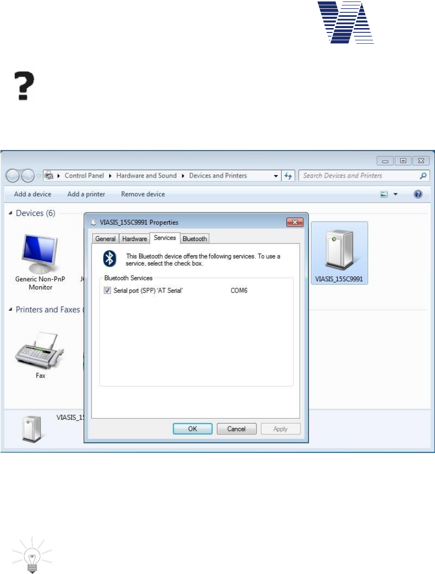
If you use other terminal software or make a manual terminal connection with
viagraph you need to know which virtual COM port number was assigned to the
Bluetooth device and set the COM port in the terminal program accordingly. This
COM port number can be either found in the Windows Device manager, see chap-
ters 6.2.2 and 6.2.3.1 or else with a right mouse click to the device, which was added in Devic-
es and Printers, menu item Properties in the Services tab, see also illustration 37 below:
Illustration 37: COM port number of the serial Bluetooth device
The radiation of the Bluetooth antenna and therefore the zone where radio connections are
possible is similar to the radar in front of the display. Directly aside, below and behind the
viasis a connection is only possible if reflectors (buildings, fences or vehicles) are nearby.
Internal Bluetooth modems of laptops, notebooks and mini computers are in
common designed for the connection of peripheral Bluetooth devices like key-
boards, mouse, mobile phones, which are placed close by your computer.
Therefore their radio transmission strength and reception sensitivity is often quite
bad. In such a case turn off the internal modem and invest a few Euro for an external class 2 or
better class 1 USB Bluetooth dongle, with which you can have a much better and stable distant
Bluetooth connection.
If you have already established some Bluetooth data connections to different viasis or more
generally to via devices in the past and these devices are still reachable while you try to con-
nect in viagraph with Connect to device you may experience the fact that viagraph
automatically connects to the first found via device and not to the device you wanted viagraph
to connect to. In this case you have choose the connection and the device manually, please see
chapter 6.2.7.
Page 24 of 85
viasis 3003 user manual
via
traffic
controlling
gmbh
6.2.6 Data connection by GSM radio modem, Email and SMS transfer
If you like to transfer data or parameter of the viasis by GSM radio link you need
in common to obtain a second GSM radio modem for the communication with your
remote computer1. The radio modem must support CSD2 protocol data communica-
tion. Further on you need two SIM cards of a provider, whose radio network
supports explicitly CSD data transfer with 9600 Baud data transfer speed.
For the use of E-mail data transfer and automatic viasis SMS alarm messages you need SIM
cards and contracts which include GPRS and SMS services. You may ask if the provider offers
contracts with data transfer only (without voice) services for business customers.
Before you obtain the SIM cards ask the provider if he covers the needed radio services
(CSD, GPRS, SMS) at the viasis measurement place(s) himself. Roaming service, the radio
service by a contractor of your radio service provider might be paid with high charges later on.
Regarding the questions „How to connect, install driv-
ers and setup your radio modem at your computer”,
please refer to the information given by the radio mo-
dem manufacturer. Finally a virtual COM port must
have been created in the Windows Device manager,
typical either in the device class COM&LPT or Mo-
dems – Properties – Extended, see also chapters 6.2.2
and 6.2.3.
Before you can connect with viagraph3 or another
minal software, check that the viasis is powered and the
radio modem is switched on by its related time
ule and (if needed) the PIN number of the SIM card is
set in the viasis, refer also to chapters 6.4.2.1 and
6.4.2.2.
In order to establish a connection with viagraph click
the button Connect to device see illustration 10 in the
viagraph start window.
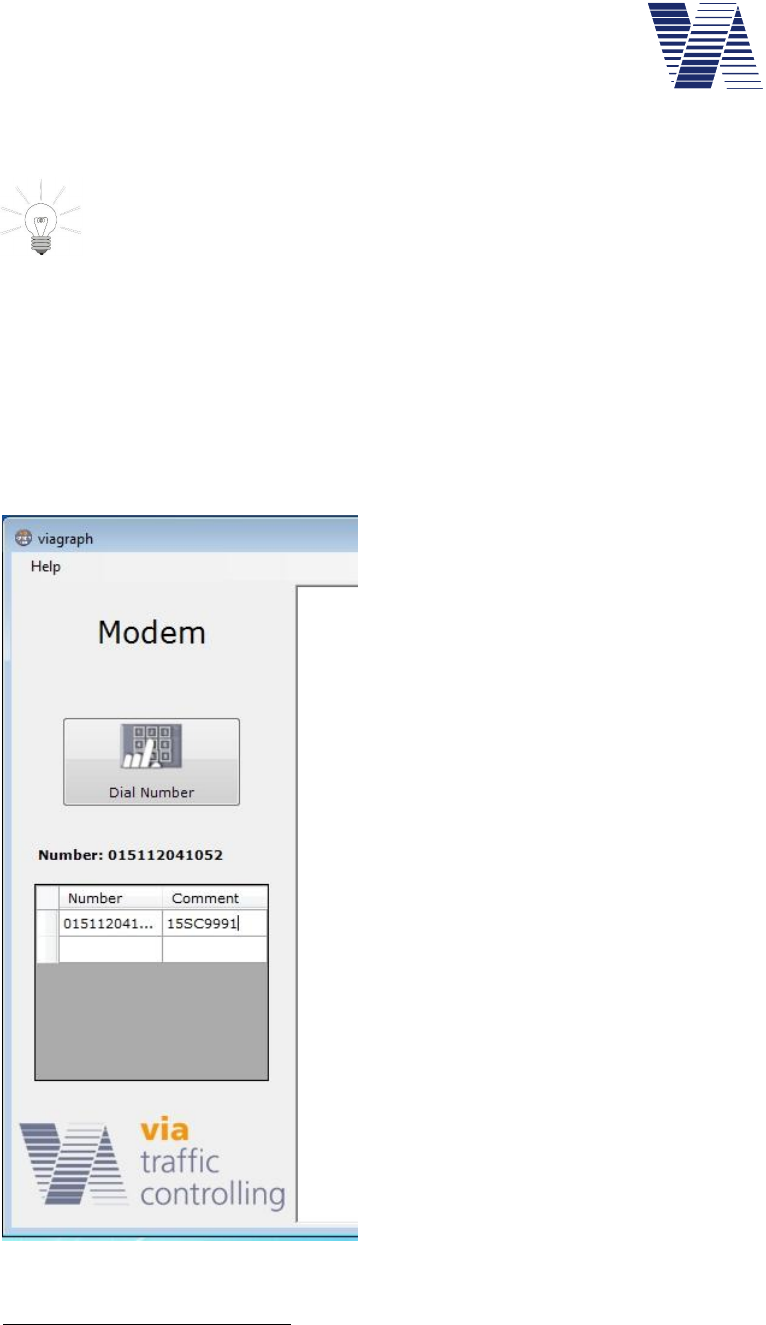
After the modem was found the Modem screen is
shown, see also illustration 38. Enter the dialing num-
ber of the SIM card inserted in the viasis in the field
Number. In the Comment field enter a unique descrip-
tion for the viasis.
1Laptop or notebook integrated radio modems or “surf sticks” often offer an integrated modem with a virtual COM port for
various radio link protocols. But in almost all cases they do not provide CSD protocol capability . Therefore check if CSD
explicitly listed in the modem features in the provided manufacturer information.
2CSD – circuit switched data
3Viagraph expects a radio modem inserted SIM card with switched off PIN number request. This can be done by inserting
the SIM card in a mobile phone. Please follow the mobile phone manual, how to do it.
Illustration 38: Viagraph radio modem sup-
port
Page 25 of 85
viasis 3003 user manual
via
traffic
controlling
gmbh
Have you already added the Number entry to the list mark it with a left mouse click and click
hereafter on the button Dial number.
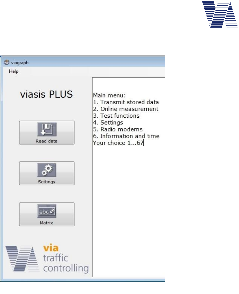
As soon the GSM data connection is
established the viagraph connection
window with the viasis main menu in
the terminal is shown, see illustration
11. Depending on the viasis type rec-
ognized by viagraph several buttons
appear on the left side of the viagraph
window, see also illustration 39 left
aside.
As soon the viagraph connection
window is closed again the modem
connection is also disconnected.
Illustration 39: Viagraph connection window and viasis main menu
Page 26 of 85
viasis 3003 user manual
via
traffic
controlling
gmbh
6.2.7 Manual selection of the viagraph communication (COM) port
The manual selection of the communication (COM) port might be necessary, in case of:
- multiple connections to different via devices are possible, but with the Connect to device
search only the first found device is automatically connected.
- several modems with virtual COM ports are installed at your computer. Viagraph always
offers only the first found modem, which is the inappropriate one for a GSM connection to the
viasis device.
- several Bluetooth connections were established in the past, each with a COM port number,
some viasis with Bluetooth modem are in reach, but only the first found device is automatically
connected by viagraph.
In this cases or a combination of them, please have a look in the Windows Device manager
(see chapters 6.2.2 and 6.2.3), particularly in the device classes COM&LPT,Bluetooth devic-
es and Modem to find the COM port number of the wished viasis device or modem.
Illustration 40: Viagraph terminal connection
Start viagraph and select Terminal from the Tools menu, see also illustration 32. The initially
empty terminal window appears. In the COM port selection field select the COM port of the
wished viasis device or modem. The data transfer rate must be always 115200 Baud. as shown
in Illustration 40. Now click the Connect button.
As soon you are connected the Disconnect button is shown. Now, you can use the Tools but-
ton, to force viagraph to show the defined extended functions for a recognized viasis or radio
modem, like Read data,Settings or Dial number, see also illustration 11 and illustration 38.
Page 27 of 85
viasis 3003 user manual
via
traffic
controlling
gmbh
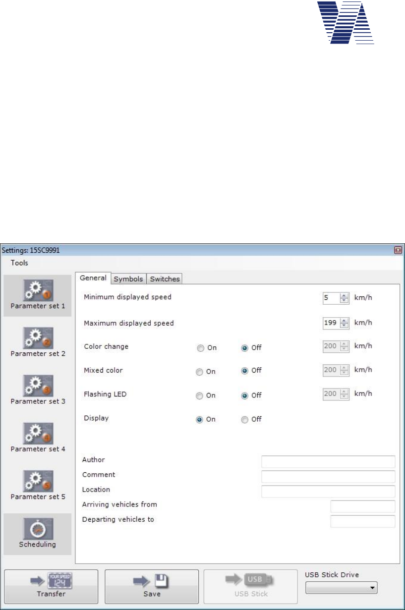
6.3 Viasis settings and parameter sets
The most often used set-
tings can be made after a
click on the Settings button
in the viagraph connection
window (see illustration 11)
in the tabs General,Sym-
bols and Switches of the
Settings window, see illus-
tration 41.
Following description is
based on the direct menu
input, which is possible with
any ASCII terminal or ter-
minal program, or also in
viagraph terminal window.
As information the input
windows of viagraph are
shown at the respective
menu descriptions.
While inputs in the menu
system are made directly to
the viasis, changes to the actual parameters shown in the viagraph input windows are cached in
the program and need to be transferred to the viasis by clicking the Transfer button, otherwise
the changes are discarded.
Hint: To avoid a malfunction of viagraph take care that the viagraph terminal window
shows the viasis main menu before you click to the „Settings“, „Matrix“, etc. button!
The viasis 3003 main menu appears after a click to the „Connect to device“ button in viagraph
automatically. If you use other terminal software, it depends on the used communication inter-
face (RS232, USB, Bluetooth, GSM) whether the main menu appears or not. If the systems
are connected and the main menu is not shown, press the „Shift“ and the „H“ key together, so
the menu will be send.
If you insert one of the selection numbers 1 till 6 in the viasis main menu, displayed in the ter-
minal window (see illustration 11) the related sub menu will be send by the viasis.
Main menu:
1. Transmit stored data
2. Online measurement
3. Test functions
4. Settings
5. Radio modems
6. Information and time
Your choice 1...6?
Illustration 41: Viagraph settings window

Page 28 of 85
viasis 3003 user manual
via
traffic
controlling
gmbh
If you enter 4for Settings in the main menu the settings menu with the current parameter val-
ues is displayed:
Settings:
1. Parameter set: 1
2. Time schedule
3. Bidirectional detection: off
4. Speed display options
5. Optimizing display: Balanced
6. Extensions thresholds
7. Radar sensitivity: 100 %
8. Back
Your choice 1...8?
The parameter values above for the items number 3, 5 and 7 are default settings ex factory.
The parameters of the sub menus Speed display options and Extensions thresholds constitute
aParameter set. A Parameter set is valid for the times defined in the Time schedule. Here-
with different display parameters can be set for different weekdays or daytimes in a flexible
way.
The settings for Bidirectional detection,Optimizing display and Radar sensitivity are the
same for all parameter sets and times.
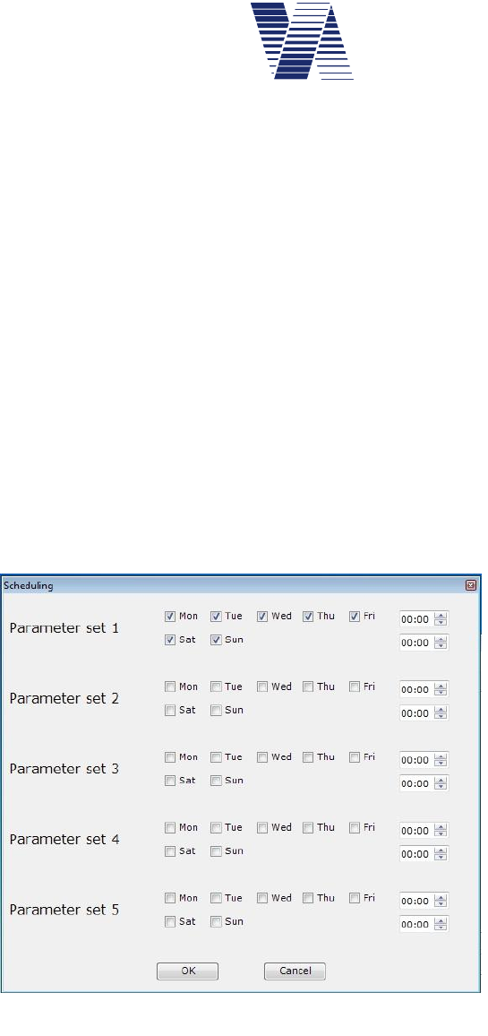
6.3.1 Parameter set
A parameter set is the collection of all display parameters of the submenus Speed display op-
tions and Extensions thresholds and its submenus for the times defined in the submenu Time
Schedule.
Up to 5 complementary parameter sets for different periods can be used for a variable meas-
urement and display behavior. This can be used for example during school hours in order to set
a different display behavior in case of a temporary speed restriction, as to the other times of the
day off school and weekends, for example at 30 km/h, from Monday till Friday, from 7:30 to
13:30 o’clock only.
With the entry 1 in the Settings menu you can change the parameter set shown in the con-
cerned submenu Speed display options and Extensions thresholds :
Settings:
1. Parameter set: 1
2. Time schedule
3. Bidirectional detection: off
4. Speed display options
5. Optimizing display: Balanced
6. Extensions thresholds
7. Radar sensitivity: 100 %
8. Back
Your choice 1...8?1
Page 29 of 85
viasis 3003 user manual
via
traffic
controlling
gmbh
In the following command prompt, select the desired, such as the second parameter set:
Parameter set=2
If you look in the submenus Speed display options and Extensions thresholds you will find
now the values of the 2nd parameter Set. In the submenu Time Schedule you find the valid
times and days which are defined for the 2nd parameter Set.
If you want to know which parameter set is active in the viasis you need to look into the main
menus submenu Information and Time.
In the viagraph Settings input window by default only the parameters of parameter set 1 are
shown, see illustration 41. Just after the release in the menu Tools – Parameter sets - On, the
access to all parameter sets and the combined time schedule Scheduling gets visible, see also
illustration 42.
Illustration 42: Parameter sets and time schedule
Page 30 of 85
viasis 3003 user manual
via
traffic
controlling
gmbh
6.3.2 Time schedule
Each parameter set, see chapter 6.3.1, owns a time schedule, which determines during which
times the settings of the parameter set are used by the viasis for the measurement, display and
possible extensions
Time schedule:
1. LED display: on
2. Operation weekdays: Su,Mo,Tu,We,Th,Fr,Sa
3. Daily start time: 00:00
4. Daily stop time: 00:00
5. Back
Your choice 1...5?
The values of the time schedule shown above are the default values for parameter set 1 ex fac-
tory. All weekdays are operation weekdays and the daily operation time is the whole day in
case daily start and stop time are set to equal values. So parameter set 1 is valid the whole
week for each day. For the other parameter sets is by default no operation day defined, there-
fore they are deactivated.
In time periods not covered by the
time schedules, no measurements
and self evident no display opera-
tion will happen. The viasis is in a
low power energy saving mode,
without active radar and the viasis
will be “awaked” only at the next
valid time schedule time entry.
If the operation time of two or more
parameter sets overlap, always the
parameters of the lowest number
parameter set get valid.
In viagraph the time schedules of all
parameter sets are concentrated in
the input windows „Scheduling“,
which gets visible by activation of
the menus Tools – Parameter sets –
on, see illustration 42 and illustration 43.
6.3.2.1 Time schedule – Led display
This option permits a hidden measurement and storage of vehicle speeds without a visible out-
put on the numeric LED display for the vehicle driver. This function can be also realized if the
minimal and the maximal displayed speed parameters are set to equal values, see also 6.3.4.2.
Illustration 43: Time schedule

Page 31 of 85
viasis 3003 user manual
via
traffic
controlling
gmbh
Enter 1 in the Time schedule menu and the following menu choice is offered:
LED display:
1. off
2. on
Your choice 1...2?
6.3.2.2 Time schedule – Operation weekdays
In the submenu Operation weekdays the days are chosen, at which measurements shall be done
and depending to other settings of the parameter set the speed shall be shown on the numeric
LED speed display or other actions defined in the Extensions thresholds shall be made.
The menu Time schedule (chapter 6.3.2) lists the current operation weekdays, e. g. Su, Mo,
Tu, We, Th, Fr, Sa of the parameter set.
After selecting 2 in the menu Time schedule you are asked to select the day you want to
change in the submenu Weekday :
Weekday:
1. Sunday
2. Monday
3. Tuesday
4. Wednesday
5. Thursday
6. Friday
7. Saturday
Your choice 1...7? _
The chosen day of the week is added to the list of operation days in the Time schedule menu,
if it was not listed before, respectively removed from the list, if it was listed.
6.3.2.3 Time schedule – Daily start and daily stop time
The daily start and stop time determine the daily time of the measurement and display opera-
tion at the chosen operation weekdays (chapter 6.3.2.2).
If the Daily start time and the Daily stop time is set to the same time values, these times are
ignored by the system and the task is performed at the whole selected operation weekdays.
You have to insert the time values in the format hh:mm. Valid are time values between 00:00
and 23:59.
Examples:
1. You intend to measure in front of a school only during school visiting times. Only at
schooldays from Monday till Friday, in the time from 07:30 till 13:30 the viasis shall measure
and display the vehicle driver’s speed.
Following settings must be made in parameter set 1 in the time schedule menu:
- Set LED display to „on“.
- Change the operation weekdays to „Mo,Tu,We,Th,Fr“.
- Set the daily start time to „07:30“ and the daily stop time to „13:30“

Page 32 of 85
viasis 3003 user manual
via
traffic
controlling
gmbh
- If set, the operation weekdays of the other parameter sets must be discarded.
2. You want to measure at a road construction site by night from 19:00 till 06:00 display the
vehicle driver’s speed. But you want to measure the whole day around the clock.
Following settings must be made in parameter set 1 in the time schedule menu:
- Set LED display to „on“.
- Change the operation weekdays to „ Su,Mo,Tu,We,Th,Fr,Sa “.
- Set the daily start time to „19:00“ and the daily stop time to „06:00“
Additionally following settings need to be done in parameter set 2 in the time schedule menu:
- Set LED display to „off“.
- Change the operation weekdays to „ Su,Mo,Tu,We,Th,Fr,Sa “.
- Set the daily start time to „6:00“and the daily stop time to „19:00“
In the second example with the time schedule of parameter set 1 a measurement with numeric
speed display is made from 19:00 till 6:00 o’clock each night. During the daytime from 06:00
till 19:00 o’clock the time schedule of parameter set 2 measures without displaying the speed
on the numeric LED display.
6.3.3 Bidirectional detection
The viasis radar detects also the data of leaving vehicles, whose data by default are not stored
in memory and whose speed in principle are not shown on the numeric LED display. The fea-
ture Bidirectional detection allows an additional memorization of data of leaving vehicles for
later data evaluation purposes.
If you enter 3 in the „Settings” menu you are prompted to change the Bidirectional detection
state:
Bidirectional detection
1. off
2. on
Your choice 1...2?
Is the Bidirectional detection set to “on” you are given in the Online measurement menu the
speed data of vehicles of both driving directions by the serial data connection(s), see chapter
6.6.
Hint: The bidirectional detection delivers only at low traffic density, respectively low
vehicle meeting rate, complete and meaningful data for the leaving vehicle traffic,
whose vehicles cannot be detected as long they are in the radar shadow of approach-
ing vehicles.
The setting for the Bidirectional detection is valid for all parameter sets. In viagraph the fea-
ture Both directions can be activated in the Tools menu of the Settings window.

Page 33 of 85
viasis 3003 user manual
via
traffic
controlling
gmbh
6.3.4 Menu Speed display options
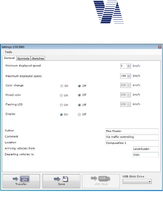
The menu Speed display options is shown if you choose 4 in the Settings menu:
Speed display options:
1. Decimal places: off
2. Minimal speed displayed: 5 km/h
3. Maximal speed displayed: 199 km/h
4. Threshold blinking LED: 200 km/h
5. Threshold Led mixed color: 200 km/h
6. Threshold LED color change: 200 km/h
7. Back
Your choice 1...7?
The parameter values shown above are the default values ex factory.
For viasis LED displays with only one LED color the options Threshold LED mixed color
and Threshold LED color change do not exist. The Threshold LED mixed color is only
shown for viasis with two appropriate LED colors. The options given in menu “Speed display
options”, with exception of the Decimal places, need to be defined for each activated parame-
ter set.
6.3.4.1 Decimal places
For applications where low vehicle speeds shall be measured exactly, e. g. for drive in weigh-
bridges, the display of a decimal digit until 19,9 km/h (or mph) can be activated by entering 1
in the Speed display options menu and further activating the decimal:
Decimal places
1. off
2. on
Your choice 1...2?
If vehicle speeds above or equal 20 km/h are measured the speed values are displayed on the
numeric LED display as whole numbers again. If the speed decimal is activated the speed data
output in the Online measurement (chapter 6.6) mode, is also given with a decimal digit.
The setting for decimal places is a general setting equal for all parameter sets.
6.3.4.2 Minimal - and maximal speed displayed
The „Minimal speed displayed“ is the lowest measured speed value published on the numeric
LED speed display
In the “Settings” menu you are prompted after the selection 4:
Minimal speed displayed = _
End the numbers input with <return >. The new value is shown in the menu immediately.
The values for minimum speed can be set in the range between 5 and 199 km/h. Only values
lower or equal the adjusted maximum speed will be accepted by the system.

Page 34 of 85
viasis 3003 user manual
via
traffic
controlling
gmbh
You may raise the minimal speed factory setting of 5 km/h to e.g. 15 km/h to suppress slow
movements of vehicles, pedestrians or wind moved branches of trees, which may also initiate
measurements on short distance.
The „Maximal speed displayed“ is the highest measured speed value shown on the numeric
LED speed display. With the 2 ½ - digit LED display you may set the value between adjusted
minimal speed and a maximum of 199 km/h.
The reduction of the Maximal speed displayed to values just above a local speed limit (maybe
plus 20%) avoid the driver testing of the maximal shown speed or „tachometer checks“.
The setting of the Maximal speed displayed parameter is analogue the setting of the Minimal
speed displayed. The setting can be changed by the selection 5 in the Settings menu.
Both settings have no influence on the speed data storage and the output of serial data. All
speeds measured between 5 km/h and 199 km/h are stored, respectively transferred to a con-
nected computer terminal.
Hint: By setting minimal and maximal speed displayed to equal values e. g. to 5
km/h, the vehicle speed data are memorized, resp. transferred to a connected termi-
nal, without an output on the numeric LED display for the vehicle drivers, see also
chapter 6.3.2.1.
6.3.4.3 Threshold blinking LED
Depending on the excess of the „Threshold blinking LED“ by the measured vehicle speed, the
numeric speed display is alternated for 0.25 seconds on and 0.25 seconds off time. In a display
update cycle with 1.5 seconds length the numeric speed „blinks“ up 3 times in short sequence.
This function can be used to reduce the power consumption of the system, with the effect of
nearly doubling the system operating time without battery recharge. Hereby the threshold value
is set to the minimum speed.
If the threshold is set to a local speed limit, this function can be used to point over speeding
drivers to their misbehavior, with the effect of a blinking (warning) display when the speed
limit is exceeded.
The threshold is set like the other thresholds in the range from 5 km/h till 200 km/h (blinking
deactivated).
6.3.4.4 Threshold LED mixed color (Option)
If the viasis is equipped with two LED colors, which can be shown at the same time and emit
seemingly a third color, the parameter “Threshold LED mixed color” is shown. Practically if
the viasis has e. g. green and red LED the result of displaying both colors is the mixture color
yellow, which is displayed if a measured vehicle speed exceeds the related, set threshold.
The speed threshold parameter is set similar to the speed threshold LED color change, see also
chapter 6.3.4.5.
For example if the viasis is equipped with yellow and red emitting LED the color sequence of
the display yellow – orange – red would be chosen with rising measured speed values, the
mixed LED color threshold (orange display) would be set to 31 km/h and the threshold LED
color change to 41 km/h.
Is the LED mixed color threshold set to a higher value than the LED color change threshold it
will have no visible effect on the display.

Page 35 of 85
viasis 3003 user manual
via
traffic
controlling
gmbh
6.3.4.5 Threshold LED color change
The viasis is supplied in several versions, with a numeric LED display with one or two LED
colors. Only the two color versions have a menu item for changing the LED display color de-
pendent of the measured vehicle speed. The color of the numeric speed display changes, for
example from yellow to red color, if a detected vehicle moves faster than the set “Threshold
LED color change” speed limit.
Also this option can be used to indicate the vehicle drivers that they drive too fast and their
vehicle speed exceeds the local speed limit.
The threshold is set like the other thresholds in the range from 5 km/h till 200 km/h (numeric
speed display color change deactivated).
6.3.5 Optimizing display
The viasis is equipped with a sensor for the environment brightness. With the measured values
the needed brightness of the display LEDs for a good visibility is calculated and controlled.
With the menu Optimizing display the LED display brightness can be influenced if needed:
Optimizing display
1. Operating time
2. Balanced
3. Visibility
Your choice 1...3?
If the option Operating time is chosen the display appears darker and reaches maximal 50% of
the possible brightness adjusted ex factory. If you choose Visibility the LED display appears to
be brighter in compare to the Balanced setting. Here the viasis reaches the adjusted maximal
brightness earlier and needs up to 50% more battery energy with the consequence of having a
reduced operating time with battery supply.
6.3.6 Menu extensions thresholds
The viasis can be equipped with several optional extensions, which can be divided in two
groups.
One group are the LED display extensions in form of LED warning symbols, which are inte-
grated in the numeric LED speed display field, which are shown alternating to the numeric
speed values, see chapter 6.3.6.1.
The other group consists of controlled switches as relays or power MOSFET transistors
switches or switched optical output units, like LED warning lamps, LED matrices with text or
symbols, which are activated additionally to the numeric LED speed display at the same time,
see also chapter 6.3.6.2 foll.
All switches or output units are activated by the excess of a set speed threshold by
the measured vehicle speed. More precisely an “on and an off speed threshold can
be set for each symbol, switch or peripheral device.

Page 36 of 85
viasis 3003 user manual
via
traffic
controlling
gmbh
The following „Extensions thresholds“ menu is an example. Number and sequence of the
submenus depend on the installed viasis equipment:
Extensions thresholds:
1. Led symbols 30,50,60
2. Led symbols 70,80,!
3. Led symbols smileys
4. Led warning light
5. Relays
6. Display pages
7. Definition of symbols
8. Back
Your choice 1...8?
The first three menus Led symbols... are predefined by default. These symbol menus and their
contenting symbol definitions can be changed, however not the number of symbols in the men-
us, see chapter 6.3.6.2.
6.3.6.1 Thresholds LED circle symbols
The viasis is delivered with integrated signs, red
LED circle symbols with white speed limit (di-
ameter 300 mm). The related speed thresholds
for the activation and deactivation are placed in
the Settings - Thresholds Extensions menu.
The display of speed limit or warning symbols
alternates with the numeric speed display. The
display is changed each ¾ second (750 ms).
If you select LED symbols 30, 50, 60 in the
Thresholds Extensions menu the following
submenu for the related speed thresholds is
shown:
Led symbols 30,50,60:
1. Symbol 30 on: 31 km/h
2. Symbol 30 off: 50 km/h
3. Symbol 50 on: 200 km/h
4. Symbol 50 off: 200 km/h
5. Symbol 60 on: 200 km/h
6. Symbol 60 off: 200 km/h
7. Back
Your choice 1...7?
For each symbol an „on“ and „off“ speed threshold can be set between 5 km/h and 200 km/h
(threshold inactive). Is the measured speed below the “on” or above the „off“ threshold only
the numeric speed is displayed. In the menu example above the speed limit 30 symbol is shown
at measured speeds from 31 km/h till 49 km/h alternating to the numeric speed.
Illustration 44: Circle symbol 50
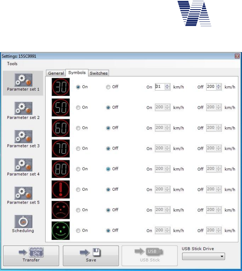
Page 37 of 85
viasis 3003 user manual
via
traffic
controlling
gmbh
In viagraph the speed thresholds of the circular warning symbols are set in the Symbols tab for
the selected parameter set, see illustration 45 below:
Illustration 45: Viagraph symbol tab
6.3.6.2 Definition of symbols
The predefined symbols in the first three menus of the Thresholds Extensions menu, see chap-
ter 6.3.6, can be changed, however not the number of symbols in the menus.
For example if you need the circle symbols 8, 25 and 50 instead of the symbol group 30, 50
and 60, you may enter 7 in the Thresholds Extensions menu and the symbol group you want
to change is requested:
Select symbol group
1. 30, 50, 60
2. 70,80,!
3. Smiley
Your choice 1...3?1
Choose with 1 the symbol group 30, 50, 60 and enter a new name for the symbol group (max.
31 characters long):
New symbol group name = 8,25,50 < Return >
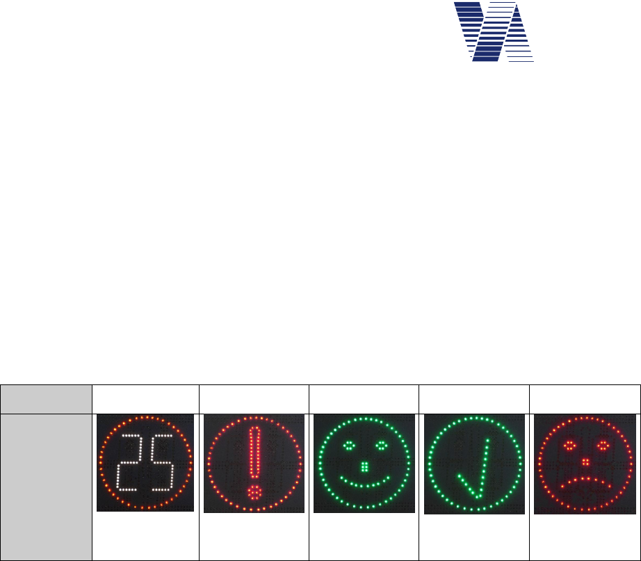
Page 38 of 85
viasis 3003 user manual
via
traffic
controlling
gmbh
Now each new symbol name (max. 11 characters) with a related font number, see also table 1,
must be inserted:
Symbol name: 8 < Return >
Font: 408 < Return >
Symbol name: 25 < Return >
Font: 425 < Return >
Symbol name: 50 < Return >
Font: 450 < Return >
On the two digit 7 segment number display in the circle all numbers between 1 ... 99 can be
shown. For the font number you must add 400 to the number, which shall be displayed. What
means to display 25 in the circle you must enter 25 + 400 = 425 for the font number. Besides
the numbers in the circle there are four further circle symbols with font number 500 to 503
defined, see following table 1:
Font 401 .... 499 500 501 502 503
Symbol
Example 425
Table 1: Font numbers of the circle symbols
In the later menu presentation the text “Led symbols” is automatically inserted ahead and in
front of each symbol name the text “Symbol” within the new menu.
After insertion the menu Extensions Thresholds is repeated by the viasis with the new menu
items:
Thresholds Extensions:
1. Led symbols 8,25,50
2. Led symbols 70,80,!
3. Led symbols smileys
4.....
6.3.6.3 LED Warning lights (Option)
If the viasis is delivered with one or more LED warning flash lights in the menu Thresholds
Extensions a related submenu Warning light or similar will appear:
LED warning light
1. Yellow LED on: 200 km/h
2. Yellow LED off: 200 km/h
3. Red LED on: 200 km/h
4. Red LED off: 200 km/h
5. Back
Your choice 1...5?

Page 39 of 85
viasis 3003 user manual
via
traffic
controlling
gmbh
Depending on the warning light features (uni-/bi- or tricolor) the items of the menu will vary.
The LED of the warning light are switched on or off synchronously to the numeric speed dis-
play in case the related on/off threshold is exceeded by the measured speed value. The speed
threshold for the activation/deactivation of the LED color(s) of the warning light can be set
between 5 km/h and 200 km/h (threshold deactivated).
6.3.6.4 Relays and power MOSFET transistors (optional)
The viasis 3003 can be ordered with up to 7 galvanic isolated low voltage relays, appropriate
for switching up to 230 V mains voltage or alternatively with up to 7 high current MOSFET
power transistor to switch 12VDC loads, technical data see chapters 10.3.5.
The connection is made either in an external waterproof (IP65) connection box with number
labeled screw clamps or the viasis is delivered a connection cable (and scheme) ex factory.
For three installed relays the menu for their related speed thresholds in the menu Extensions
Thresholds – Relays will look similar to the following menu:
Relays
1. Relay 1 on: 31 km/h
2. Relay 1 off: 51 km/h
3. Relay 2 on: 51 km/h
4. Relay 2 off: 61 km/h
5. Relay 3 on: 61 km/h
6. Relay 3 off: 81 km/h
7. Back
Your choice 1...7?
The relays or MOSFET transistors are switched synchronous to the numeric speed display in
case the related speed thresholds are exceeded by the measured vehicle speed. In the menu
example above relays 1 is switched for measured speeds from 31 km/h till 50 km/h.
6.3.6.5 LED display pages or additional LED fixed text (viasis PLUS or PLUS SMILE)
The submenu Display pages is placed in the menu Extensions Thresholds in case the viasis is
equipped with additional LED fixed text or symbols (variant viasis PLUS SMILE) or a LED
full matrix (variant viasis PLUS) below the numeric speed display for the display of additional
text or symbols.
For an additional board with three fixed texts the related menu may look as follows:
Display pages:
1. THANK YOU on: 5 km/h
2. THANK YOU off: 31 km/h
3. SLOW DOWN on: 31 km/h
4. SLOW DOWN off: 41 km/h
5. Sad face :-( on: 41 km/h
6. Sad face :-( off: 200 km/h
7. Back
Your choice 1...7?
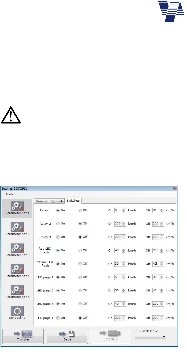
Page 40 of 85
viasis 3003 user manual
via
traffic
controlling
gmbh
For LED fixed texts (PLUS SMILE) the displayed text or a symbol name will be used to label
the menu items, for LED full matrices with variable texts and symbols the menu items are la-
beled only as numbered LED page (1, 2, ... etc.).
For each text or symbol can be defined an „On“ and „Off“ threshold between 5 km/h and 200
km/h (threshold deactivated).
The text or the symbol is switched synchronous to the numeric speed display if the related
threshold is exceeded by the measured speed value. Moreover the switched outputs (relays, ...,
display pages) are also activated outside the range of the set minimal and maximal speed dis-
played thresholds for the numeric speed display, so that for example with the viasis PLUS
additional text like “Slow down” can be also shown without having a numeric speed displayed.
For viasis PLUS SMILE with LED fixed text the activation range of two or more
texts shall not overlap. The simultaneous display of two fixed texts will cause an
unreadable result.
The viasis PLUS shows in case of the simultaneous activation of two or more LED pages, the
pages in an alternating sequence each for the time of measurement cycle (typ. 1,5 s). This fea-
ture can be used e. g. in bi-lingual regions to show additional text in two languages in an
alternating manner. For example Led page 1 shows the text „THANK YOU“, Led Page 2
shows the welsh text „DIOLCH YN FAWR“, the „On“ threshold for both pages is set to 5
km/h and the „Off“ threshold to 30 km/h – as result for the time of detection of a 28 km/h driv-
ing vehicle the texts „THANK YOU“ and „DIOLCH YN FAWR“ are shown alternating each
for 1,5 seconds.
In viagraph
switched out-
puts are placed
in the tab
Switches of the
parameter sets,
see illustration
46.
The viagraph
settings Switch-
es tab example
represents a
viasis PLUS
with 4 Led pag-
es, three relays
and a bicolor
LED warning
flash light (yel-
low/red LED).
Illustration 46: Viagraph settings tab switches

Page 41 of 85
viasis 3003 user manual
via
traffic
controlling
gmbh
6.3.7 Radar sensitivity
With the menu item Radar sensitivity the gain of the analogue receiver amplifier, preset to a
gain of 100%, can be reduced in steps of 20%. In consequence the detection distance range of
the viasis will be reduced. This feature can be used to avoid or at least reduce the detection of
diagonal moving traffic of a crossing in front of the viasis, see also chapter 5.2.2.
The radar sensitivity can be set to the values 100, 80, 60, 40 and 20 per cent, other values are
rejected.
6.4 Radio modems
Which optional radio modems are installed and found during power on initialization can be
seen in the information header of the menu „Information and Time”, see chapter 6.5.
The content of the menu Radio modems varies depending on installed radio interfaces:
Radio modems:
1. Bluetooth modem
2. GSM/GPRS modem
3. GPS module
4. Back
Your choice 1...4?
If the submenu of a not installed radio modem is called only the hint „Not installed!“ is shown.
For the menus Radio modems and Information and time exists (yet) no input screen in the
viagraph program.
6.4.1 Bluetooth modem
If you select „1. Bluetooth modem“ in the radio modems menu the Bluetooth menu is shown:
Bluetooth menu
1. Device name
2. Pin number
3. Information
4. Back
Your choice 1...4?
With the choice of 3. Information the current settings of the viasis Bluetooth modem are de-
rived, which will look ex factory similar to the following:
Laird Bluetooth Data Module 730-SA
Version 11.28.0
Bluetooth address = 0016A40D81AE
Device name = "VIASIS_15SC9991"
Trusted device list:
001583501455
001167559110
001A7DDA710D
Clear list (y/n)?

Page 42 of 85
viasis 3003 user manual
via
traffic
controlling
gmbh
The Bluetooth address, is a unique and user unchangeable hardware address provided by the
Bluetooth modem manufacturer.
The device name is the chosen name for the viasis Bluetooth devices shown if you search for
connectable devices under Windows on your computer.
The Trusted device list are the Bluetooth hardware addresses of computers to which the viasis
was once successfully connected.
The Trusted device list might have to be cleared :
-if more than 20 Bluetooth addresses are already shown in the list. Herewith the list is full
and the Bluetooth interface in the viasis will not accept connections to new computers with
new Bluetooth addresses.
-if the pin number or the device name of a trusted device was changed
Hint: Access to the menu Bluetooth modem is either only possible via USB or a
RS232 serial cable connection. If you try to make an illegal access e.g. by Bluetooth
or GSM connection the hint Access impossible! will be displayed on a connected
terminal.
6.4.1.1 Bluetooth device name
The so called local device name can be changed and is set by default to „VIASIS-15SC9991“,
wherein “15SC9991” is the unique viasis serial number. After you selected 1. Device name in
the Bluetooth menu you are asked to enter the new device name:
Device name = MyBluetooth001
The character string is to be ended by pressing the <Return> key. The device name may consist
of 1 till 40 characters. Avoid special characters, apostrophes and similar, because they are in
common interpreted by connection software and this often in a different way.
6.4.1.2 Pin number
If you choose 2 for the Pin number in the Bluetooth modem menu you are asked to enter a
new pin number:
Pin number=8241
The pin number itself can be changed, the length of the pin number can be up to 8 digits. All
numbers from 1 till 99999999 are valid pin numbers. If a not correct pin number is send by a
connecting computer the connection is refused by the viasis, therefore the number protects the
viasis from unwished access.

Page 43 of 85
viasis 3003 user manual
via
traffic
controlling
gmbh
6.4.2 GSM/GPRS Modem
The GSM/Email menu is shown if you enter 2 in the Radio modem menu (see also chapter
6.4):
GSM/Email menu:
1. Time schedule
2. Pin number
3. Configure GPRS
4. Configure SMTP-Server
5. Configure EMAIL
6. Configure SMS
7. Back
Your choice 1...7?
The following chapters describe each menu item.
6.4.2.1 GSM/Email time schedule
After the entry 1 at the GSM/Email menu prompt the Time schedule menu with the currently
defined time schedule settings is send. The following example shows the ex factory settings
after delivery:
Time schedule GSM/Email
1. Operation weekdays: Mo,Tu,We,Th,Fr
2. Daily start time: 08:00
3. Daily stop time: 18:00
4. Email delivery: None
5. Back
Your choice 1...5?
The setting of the GSM Operation weekdays and the Daily start/stop time is done similar as
the settings made in the time schedule for measurement and LED display, please refer to the
chapters 6.3.2.2 and 6.3.2.3.
The menu items Operation weekdays and Daily start/stop time define only the
days and the time span during which the viasis GSM/GPRS modem remains
powered and can be called by a dial up GSM connection. The delivery of Email
and SMS messages and data works independently from the herewith defined time
schedule and are also send outside the here defined days and times.
To reduce the available times, where the viasis radio modem can be called, means to extend the
operating time of battery supplied viasis systems remarkably. This due to the fact that the basic
power consumption while measuring without active LED display is four times higher if the
GSM/GPRS modem is powered. A 24 hour availability of a radio connection to the viasis is in
common not needed, because reconfigurations are necessary quite seldom, most often during
workdays and only in the common working times (08:00 till 18:00). For an individual time
setting and a possible further reduction of the power consumption you can use the described
menu items.
During an active GSM connection the modem is not powered off. The modem is switched off
as soon as the connection is closed hereafter.

Page 44 of 85
viasis 3003 user manual
via
traffic
controlling
gmbh
Before you configure the Email delivery, please set the PIN number first in case the SIM card
is already inserted, see also next chapter.
The submenu Email delivery offers different possibilities to initiate the sending of measure-
ment data E-mails:
Email delivery:
1. None
2. Memory full
3. Daily
4. Weekly
5. Monthly
Your choice 1...5?
The selection Memory full sends a mail with the measurement data as a file attachment if more
than 95% of the data flash storage of the viasis is full.
Further you can choose the time intervals Daily,Weekly or Monthly. If you select them addi-
tional menu options for the delivery time and possibly the date appear in the menu. For this
options always a mail is send also if no measurements were stored in the selected time interval.
If you select Daily mail delivery you need to define the daily delivery time:
4. Email delivery: Daily
5. Time: 03:00
The time value is set in the format “hh:mm”, with time values between 00:00 and 23:59.
For the mail delivery interval Weekly additionally the day of the week, where the mails shall be
send must be set:
4. Email delivery: Weekly
5. Time: 03:00
6. Weekday: Wednesday
If you enter “6” for the Weekday selection a sub menu is shown, which lists all weekdays for
your choice.
If the mail delivery is set to Monthly the day of the month need to be given instead:
4. Email delivery: Monthly
5. Time: 03:00
6. Day of month: 1
Legal month values are 1 to 28 only in order to avoid delivery gaps in the short months of the
year, e. g. in February.
Further hints:
Use delivery (night) times with low traffic density and low GPRS data transfer
volumes. During the time the mail needs to be delivered no vehicle data can be
measured and stored. The minimal delivery time for e. g. an 4 MB data long mail
is ~12 minutes. The GPRS upload bandwidth must be shared with other devices
uploading data to a radio base station.

Page 45 of 85
viasis 3003 user manual
via
traffic
controlling
gmbh
Whether an E-Mail or SMS must be delivered is checked once per minute by the viasis. If a
delivery cannot be done due to an active Bluetooth, USB or GSM data connection, the transfer
its started within a minute after the closure of the connection. Is a viasis powered off during
the scheduled time of delivery, the E-mail will not be sent after the next power on anymore.
An E-mail delivery is valued valid as soon as the mail server (SMTP-server) acknowledges
the data reception and the server connection is closed regularly. In this case the stored and
transferred measurement data are erased in the flash memory automatically. Otherwise the E-
mail delivery is repeated within a minute after the failure and until the transfer is successful.
Be aware if you use the daily interval a lot of small data files is created, which must be
merged later on to be able to create e. g. a week long evaluation.
6.4.2.2 SIM card PIN code
The input of the PIN1 code or the request of its set status can only be done by a serial RS232
cable connection. Access by the GSM, Bluetooth or USB data connections is refused with the
message “No access possible”.
Select the GSM/E-mail menu item “2. Pin number” to enter the 4 digit PIN code delivered
from the service provider together with the SIM card, for example:
Pin number=1234 <Return>
In case the SIM2 card is already inserted in the push/pull SIM card holder located at the con-
trol panel backside in the battery box you should receive following answer:
+CPIN: READY
OK
In case of an error or problem you get one of the messages listed in the table below:
+ CME ERROR: SIM not inserted SIM card not in the SIM card holder, not
readable or defective
+ CME ERROR: incorrect password Entered PIN code is wrong
ERROR / ERROR SIM PIN PIN code wrong or already inserted
+CPIN: SIM PIN PIN code required
+CPIN: SIM PUK
3
PIN code setting failed 3 times, SIM card is
locked. You can unlock the SIM card exter-
nally only, e. g. by inserting the SIM card in
a mobile phone and insertion of the 8 digit
long PUK code 4.
If you enter <Return> only at the PIN code prompt the status of the PIN setting
is delivered without a setting and one of the status messages above are output.
Repeated insertion of the already set correct PIN code is illegal.
1 PIN – „Personal Identification Number“ - 4 digit long numeric pass code
2 SIM – “Subscriber Identity Module” – Component for radio network user identification
3 PUK – „Personal Unlock Code” – 8 digit long unlock code to be found in SIM card accompanying information of your
GSM/GPRS service provider.
4 Guidance for the procedure is in common documented in the manual of your mobile phone

Page 46 of 85
viasis 3003 user manual
via
traffic
controlling
gmbh
In case the PIN code request of the SIM card was already switched off or you change later
to a SIM card with switched off PIN request you need to delete an earlier entered and stored
PIN code by insertion of PIN number = 0 <Return>.
For the protection against misuse and theft the inserted PIN code cannot be requested
Attention: Never change the PIN code arbitrarily. The PIN code is
send from the viasis to the radio modem after each modem power on
automatically. After 3 failing attempts the SIM card is locked and the
PUK code is requested further on.
In case the inserted PIN code is rejected check your provider infor-
mation first before you retry it again.
6.4.2.3 GPRS configuration
If you select “3. Configure GPRS” in the GSM/Email menu you will receive the current GPRS
configuration. The following example shows the configuration ex factory:
APN: not set
USER: not set
PASS: not set
ROAMING: off
Change (y/n)?
In case you answer the question “Change(y/n)?” with “y” for yes, the APN (access point net-
work), the related USER username and PASS pass code will be requested sequentially by the
viasis. Valid entries are up to 31 alphanumeric characters, but without question mark, colon
and double point. The text string must be ended with <Return>. Entering <Return> only will
skip the request and the setting remains unchanged.
Thereafter you can allow or deny roaming connections, what means connections made instead
of your service provider by another provider, which will bill the connections separately to your
provider. This is in common accompanied by much higher connection charges.
You may configure GPRS access by all viasis serial interfaces (RS232, GSM, Bluetooth and
USB). But only by using the RS232 connection the configuration is immediately tested and the
protocol is send to a connected terminal:
Configure ...
AT+CGATT=0
AT+CGDCONT=1,"IP","internet.t-mobile"
AT+QICSGP=1,"internet.t-mobile","tm","tm"
AT+CGATT=1
AT+QIMODE=1
AT+QIREGAPP
AT+QIACT
AT+QILOCIP
+IP: 100.76.160.156
GPRS ok
In case of a problem or an error while establishing the GPRS connection the sequence above
ends with „Error GPRS“. If you configure by other interfaces as RS232 connection a direct

Page 47 of 85
viasis 3003 user manual
via
traffic
controlling
gmbh
test cannot be done and for a possibly occurred error you need to check the viasis protocol
(see chapter 6.5.1) to find errors of the GPRS connection establishment like “Error
GSM/GPRS”, “Error GPRS timeout”, “Error GPRS communication”....
The following table lists the GPRS access data of some European provider companies (without
warranty):
Provider / Country
APN USER PASS
T-mobile Germany internet.t-mobile tm tm
Vodafone Germany web.vodafone.de [any] [any]
O2 Germany
internet [not set] [not set]
E-
Plus Germany
internet.eplus.de eplus gprs
Mobilkom A1 Austria a1.net gprs@aiplus.at [not set]
Connect Austria Austria web.one.at [user specific] [user specific]
tele.ring Austria web web@telering.de web
LUXGSM Luxemburg Web.pt.lu [not set] [not set]
Swisscom Switzerland gprs.swisscom.ch [not set] [not set]
Orange Switzerland internet [not set] [not set]
Sunrise Switzerland internet internet internet
Request the GPRS access data if not known from your SIM card (and ser-
vice) provider.
You can delete an already made configuration entry by entering <Blank> and
<Return> hereafter.
If you contact our technical support in case of problems, please provide the output protocol
(text download or terminal snapshot) of the GPRS configuration send during RS232 connec-
tions.
6.4.2.4 Configuring the SMTP-Server (Mail server)
For the configuration of the mail server enter “4” in the GSM/Email menu and you will receive
the actual settings for the E-mail delivery to the SMTP1-Server:
SMTP-SERVER: smtp.viaxmail.de
SMTP-PORT: 25
EHOST: viaxmail.de
EUSER: send@viatraffic.de
EPASS: ****
MAILFROM: viasis@viaxmail.de
Change (y/n)?
The shown settings are the default settings ex factory and are valid data if you intend to use
our mail server for the E-mail delivery. The viasis connects the SMTP server only for the for-
1 SMTP – simple mail transfer protocol

Page 48 of 85
viasis 3003 user manual
via
traffic
controlling
gmbh
warding transport of the viasis E-mail to the final destination mail server of the recipient E-mail
account(s), which you have to enter in “5. Configure Email” (see next chapter) of the
GSM/Email menu.
Note: The use of our SMTP-server takes place on own danger and under exclusion of
any liability on the part of the via traffic controlling GmbH.
If you answer “y” to the question “Change (y/n)?” you will be prompted for each SMTP-
server setup entry. For valid inputs in the text fields see the insertion of APN, USER and
PASS in the previous chapter.
The input fields in detail:
SMTP-Server – URL1 name of a mail server which is ready to receive E-mails delivered by the
viasis. The mail server only forwards (relays) emails to the recipient(s). Alternatively to the
URL name the IP address (e. g. 192.86.102.245) of a SMTP server can also be inserted.
SMTP-Port – Up to 5 digit long port number (1...65535), at which the mail server listens to
mail delivery attempts. Typically mail servers listen at port 25, but this may differ for single
SMTP servers.
EHOST – Host name of the E-mail sender
EUSER – Senders user name of its E-mail account at the mail server. In common the E-mail
sender owns a user mail account at the providers mail server. Nowadays rarely exist also open
mail (relay) server forwarding each mail they get from whoever, with no authorized login
needed or allowed. If you use such an open relay server delete user name EUSER and pass-
word EPASS.
EPASS – Password of the above described user E-mail account. For the authentication of the
mail sender needed password for the login as user at the mail server. For open relay server the
password shall be deleted, see above. In order to avoid misuse by unauthorized third persons
the set EPASS password is output as a “******” string only.
MAILFROM – E-mail address of the mail sender
A configuration change of the SMTP-server access data can be done by all serial interface con-
nections (RS232, GSM, Bluetooth or USB) of the viasis. But only if you are connected by
RS232 directly the access to the SMTP-Server and if he is ready to receive E-mails from the
viasis is tested and a protocol send to a connected terminal (example):
Configure ...
AT+QILOCIP
+IP: 100.69.8.51
AT+QIDNSIP=1
AT+QIOPEN="TCP","smtp.viaxmail.de",25
CONNECT
220 mx01.viaxmail.de ESMTP Postfix
EHLO viaxmail.de
250-mx01.viaxmail.de
AUTH LOGIN
334 VXNlcm5hbWU6
1 URL – “Uniform Resource Locator” – unique resource name, simplified e. g. the name of a website or host in
the internet. URL names are translated by DNS (domain name system) servers in routable IP addresses.

Page 49 of 85
viasis 3003 user manual
via
traffic
controlling
gmbh
334 UGFzc3dvcmQ6
235 2.7.0 Authentication successful
MAIL FROM: <viasis@viaxmail.de>
250 2.1.0 OK
QUIT
221 2.0.0 OK
SMTP-Server ok
If the connection between viasis and SMTP-server could be established and the server declared
ready to receive E-mails from the viasis you will finally see the message “SMTP-Server ok”
otherwise “Error SMTP-Server”.
If you enter <Return> only, the text entry is skipped and the text field con-
tent remains unchanged.
To delete the content of a text field to the state “not set” enter <Blank> fol-
lowed by <Return>.
Be aware that mail servers have often limits concerning the maximal length of E-mails. Most
mail servers limits are above 10 Megabyte (= limit of our providers mail server) but in some
known cases also below. A viasis with 8 MB flash storage installed is capable of producing 12
MB long E-mails in case the storage is full. The reason is the 30% increase in data volume due
to the needed base64 coding of the binary measurement file attachment. Ask the mail server
provider about existing limits before you start to send E-mails.
In case you need to contact our technical support, please provide the protocol of the failed
SMTP-server configuration, which is essential to analyze the problem.
6.4.2.5 E-mail configuration
With the GSM/Email menu item “Configure Email” you can define the recipient(s) email ad-
dress and whether E-mail alarm messages are send or not. First the actual configuration is send
(example):
MAILTO: technik@viatraffic.de
MAILCOPY: not set
Email alarm: on
Change (y/n)?
Differing from the example no E-mail address is set by default and the E-mail alarm is switched
off. To change the setting enter “y” to the “Change(y/n)?” prompt. Valid input for the sequen-
tially asked text fields MAILTO and MAILCOPY are maximal 31 alphanumeric character long
E-mail addresses. Excluded characters are question mark, colon and double point. Further is
valid things said about the text field input of the previous two chapters.
MAILTO for the recipient of the E-mail and MAILCOPY for the recipient of an Email copy
shall contain only a single E-mail address, no lists are allowed.
With activated E-mail alarm the viasis will send E-mails for the events of “Measurement stor-
age > 95% full”, “Battery voltage < 11,5V” and for system errors. The system error emails
include up to the last 8 viasis protocol entries, see also chapter 6.5.1. The E-mails are send
latest after the minute of the occurrence of the event or failure.

Page 50 of 85
viasis 3003 user manual
via
traffic
controlling
gmbh
If you respond ‘y’ to both questions “Change(y/n)?” and “Send email(y/n)?”, a test E-mail is
send and if you a connected locally by RS232 (only), you will see the delivery protocol of the
send E-mail:
Send Email...
AT+QILOCIP
+IP: 100.66.122.19
AT+QIDNSIP=1
AT+QIOPEN="TCP","smtp.viaxmail.de",25
CONNECT
MAIL FROM: <viasis@viaxmail.de>
250 OK
RCPT TO: <technik@viatraffic.de>
250 2.1.0 OK
354 End data with <CR><LF>.<CR><LF>
250 2.0.0 Ok: queued as 8DB438049D
QUIT
221 2.0.0 Bye
EMAIL ok
In case the E-mail was send correctly and the mail server accepted the E-mail for forwarding,
you get the final “Email ok” message and otherwise “Error Email”. Moreover the E-mail re-
cipient should receive a status E-mail with just the line “E-mail delivery set!”.
By means of the “Configure E-mail” menu item you may also send currently stored measure-
ment data immediately if you respond ‘n’ to the question “Change(y/n)?” but ‘y’ to “Send
email(y/n)?”.
If you are connected by RS232 the E-mail is send immediately, else if you are connected by
GSM, USB or Bluetooth interface, the mail is send as soon as the active connection will be
closed.
If you need to contact our technical support, please provide the protocol of the
failed test E-mail delivery, what is important to analyze a problem.
6.4.2.6 Configure SMS
The menu item “6. Configure SMS” in the GSM/Email menu is used to enter the needed
phone numbers for the SMS1 delivery and to activate the delivery of SMS event and error mes-
sages:
SMS SERVICE CENTER2: +491710760000
SMS phone number: 016312345678
SMS alarm: off
Change (y/n)?
Legal insertions for the SMS service center number and the phone number of the SMS recipi-
ent are up to 16 digits long. The number of the service center is always entered with plus sign
1 SMS – short message service for text messages consisting of maximal 160 characters
2 SMS Service Centre (SMSC) receives SMS messages from the telephone/radio network, forwards and stores
messages if the receiver is currently not reachable.

Page 51 of 85
viasis 3003 user manual
via
traffic
controlling
gmbh
headed international country dialing code. The phone number of the SMS recipient needs to be
entered without country code. Moreover the hints to legal text fields contents given in the
previous chapters 6.4.2.3 till 6.4.2.5 shall be observed.
If the “SMS alarm” is active, short messages for the events “Battery voltage < 11,5V”,
“Memory > 95% full” and “System error” are send within one minute after occurrence.
If you change the SMS configuration and respond “y” to the “Send SMS (y/n)?” question, you
should receive a test SMS with the content “SMS delivery set!”. If your computer is connected
by RS232 cable locally, the protocol of the SMS delivery is shown in the terminal window:
Send SMS...
AT+CSCA="+491710760000"
AT+CMGF=1
AT+CSMP=17,167,0,241
AT+CNMI=2,1,0,0,0
AT+CMGS="016312345678"
SMS ok
If the SMS delivery was successful the protocol is ended with “SMS ok” otherwise with “Er-
ror SMS”. Similar to the delivery of E-mails the delivery of SMS is delayed if you are
connected by GSM, Bluetooth or USB interface until this active connection is closed.
If you face problems with E-mail or SMS configuration or delivery and contact
our technical support, please provide the connection protocol as text or snapshot
attached to a send E-mail. The connection protocol is essential for a failure analy-
sis.
6.4.3 GPS Module (optional)
In case the viasis 3003 is equipped with a GSM/GPRS modem an additional GPS module for
the determination of the position of the viasis can be build in. The position data are determined
regularly and they are transferred as a position list to viagraph. The last position is also send in
the text of the viasis emails:
Information:
Viasis 3003 - Version 4.16
Serial number: 15SC9991
Active parameter set: 1
Interface options: Bluetooth, USB, GSM/Email, GPS
GPS: 20.09.15, 09:45:00, 51°03.5615',N, 007°00.9070',E
Date: 20.09.2015, Sunday
Time: 11:15:33
Number of values = 24274, Memory full: 6 % Battery voltage: 13,17 V
If you open a viasis measurement data file (*.vtf) with viagraph or you make a direct connec-
tion to a viasis with GPS module and click the Tools menu in the viagraph menu bar of the
Settings window, see illustration 33, the menu item GPS coordinates is selectable.
If your computer is connected to the Internet and after a click to the Tools menu item GPS
coordinates viagraph will open your standard web browser with the Google Maps web site and
sends the viasis GPS coordinates.
The web browser shows then the map with the last viasis position, see illustration 47:
Page 52 of 85
viasis 3003 user manual
via
traffic
controlling
gmbh
Illustration 47: GPS coordinates of the viasis position in Google maps
In a direct connection to the viasis the last, most current GPS position is displayed. From an
open vtf measurement data file the first GPS position of the chosen evaluation time period is
shown.
If you enter 3 in the Radio modem menu in the viagraph terminal you will receive the menu for
the GPS module:
GPS menu:
1. Position list
2. Formatted data output
3. Raw data (NMEA-183)
4. Position fix time: 24h
5. Back
Your choice 1...5?
Due to the high energy consumption of the GPS module the position determination is not done
permanently. Instead the position is determined after the viasis power on and further continu-
ously repeated after the time set in the Position fix time. The fixation of the position, may just
need 30 seconds but also up an hour at unfavorable mounting positions, where the viasis is
placed in the satellites signal shadow behind large buildings, walls, trees or other obstacles.
After the position data are determined the GPS module is immediately shut down.
During the GPS data output, see chapters 6.4.3.2 and 6.4.2.3, the measurement of vehicles is
stopped, but not during the set regular position fixes.
6.4.3.1 GPS position list
After insertion of 1 in the GPS menu you will get first the number of stored GPS positions, for
example:
Number of GPS positions = 5
Send data (y/n)?

Page 53 of 85
viasis 3003 user manual
via
traffic
controlling
gmbh
If you enter ‘y’ the output of the position list will start:
30.09.15, 15:47:00, 51°03.5647',N, 007°00.9108',E
30.09.15, 11:46:00, 51°03.5574',N, 007°00.9081',E
30.09.15, 07:45:00, 51°03.5587',N, 007°00.9086',E
30.09.15, 03:41:00, 51°03.5593',N, 007°00.9076',E
29.09.15, 23:40:00, 51°03.5599',N, 007°00.9082',E
Delete data (y/n)?
Up to 25 GPS positions can be memorized. Because the oldest position in the list is automati-
cally overwritten by the newest position it is in principle not necessary to clear the list ever.
Separated by colons the viasis system date (DD.MM.YY) and time (hh:mm:ss), the latitude in
degree and minutes with 4 decimal digits, N/S for northern/southern latitude, the longitude in
degree and minutes with 4 decimal digits and finally E/W for eastern/western longitude of the
fixed position is shown in a line.
To make the correlation between viasis measurement data and GPS coordinates easy, the viasis
system date and time and not the satellite time (UTC1) is stored in the GPS position list.
6.4.3.2 Formatted GPS data output
After entering 2 for Formatted data output in the GPS menu, you will get following hint first:
End with <CTRL-Z>
What means you can stop the formatted output of GPS coordinate data by pressing the
<CTRL2> and the ‘z’ key simultaneously.
After the repeating headline the result of the GPS position determination follows once per se-
cond:
Satellites,UTC,Latitude,N/S,Longitude,E/W,HDOP
0,
...
2,073002,
2,073003,
3,073004,
8,073005,5103.5582,N,00700.9059,E,0.96,
...
Satellites,UTC,Latitude,N/S,Longitude,E/W,HDOP
8,073021,5103.5581,N,00700.9059,E,0.96,
8,073022,5103.5580,N,00700.9058,E,0.96,
...
9,073031,5103.5585,N,00700.9049,E,0.89,
10,073032,5103.5587,N,00700.9050,E,0.84,
The first number is number of found satellites. As soon the first satellite signal is received by
the GPS menu the UTC satellite time, here 07:30:02 (AM) appears.
1 UTC – Universal time coordinated
2 CTRL – control key, depending on your keyboard, might also labelled with CTL or likewise

Page 54 of 85
viasis 3003 user manual
via
traffic
controlling
gmbh
As soon 3 to 4 satellites signals could be found appears the output of position data – the lati-
tude in degree and minutes with 4 minute decimals, the N/S latitude information and the
analogous data for the longitude.
The last number, the HDOP1 value is a measure for the horizontal, two dimensional variation
of the measured GPS data. GPS position data with a HDOP value greater than 10 are not pre-
cise and not usable.
With the GPS data output you may check if a sufficient number of satellites re-
spectively the GPS position is found at a viasis mounting place within a
reasonable time. In tunnels or in between high buildings the determination of the
GPS position might be impossible. In such a case switch the GPS position deter-
mination off, see chapter 6.4.3.4, in order to avoid a permanent searching GPS module with
the consequence of a reduced operation time of a viasis with battery supply.
6.4.3.3 GPS raw data (NMEA-183 protocol)
The GPS raw data output delivers position data coded according the nautical standard NMEA2
developed for the communication between navigation system of ships. These ASCII block data
send once per second are a bit confusing, but include numerous information, amongst other
things e. g. to the satellites, whose data were used for the calculation of the position:
$GPRMC,073114.000,A,5103.5574,N,00700.9062,E,0.00,0.00,011015,,,A*64
$GPVTG,0.00,T,,M,0.00,N,0.01,K,A*3C
$GPGGA,073114.000,5103.5574,N,00700.9062,E,1,7,1.05,75.5,M,47.6,M,,*63
$GPGSA,A,3,05,25,26,29,31,21,23,,,,,,1.36,1.05,0.86*01
$GPGSV,3,1,12,29,71,062,52,31,54,235,46,26,44,296,48,25,40,118,49*70
$GPGSV,3,2,12,21,37,178,37,39,28,157,,05,16,067,46,16,16,296,44*79
$GPGSV,3,3,12,20,11,116,47,23,09,320,45,02,09,039,44,12,,,39*4D
$GPGLL,5103.5574,N,00700.9062,E,073114.000,A,A*57
In the Internet and the literature a lot of publications describe the contents of the NMEA-183
data blocks, therefore we resign to do it here.
Similar to the formatted data output, see chapter 6.4.3.2, the output of the GPS raw data can
be stopped by simultaneous pressing of the <CTRL> and ‘z’ key.
6.4.3.4 GPS position fix time
A few minutes after the viasis power on the determination of the GPS position is done. The
Position fix time is the time period after which the determination is regularly repeated.
After insertion 4 in the GPS menu, following prompt appears:
Position fix time =
You may enter values between 1 and 255 hours for the position determination interval. The
default value is 24 hours. If you enter 0 the determination of the GPS position is deactivated.
If no valid GPS position can be determined within 60 minutes, the position search will be can-
celled and the GPS module will be switched off until the next viasis power on in order to avoid
a fast unwished battery discharge. This might be the case when operating the viasis within
buildings, tunnels or behind high buildings.
1 HDOP – Horizontal dilution of precision
2 NMEA - National Marine Electronics Assoziation

Page 55 of 85
viasis 3003 user manual
via
traffic
controlling
gmbh
6.5 Menu information and Time
The menu Information and time, which is reached by inserting 6in the main menu, is headed
by general information to the viasis soft- and hardware:
Information:
Viasis 3003 version 4.16 , H4
Serial number: 15SC9991
Active parameter set: 1
Comments: Via traffic controlling GmbH, Maybachstr. 39, 51381 Leverkusen
Interface options: Bluetooth, USB, GSM/Email, GPS
1. Protocol
2. Comments
3. Date: 04.09.2012, Tuesday
4. Time: 13:57:46
5. Daylight saving time: off
6. Back
Your choice 1...6?
The first line Viasis 300M3 Version 4.16, H4 includes viasis type designation, software ver-
sion number and hardware release. The second line displays the unique serial number of the
viasis device. Serial number, software and hardware release should be always at your hands in
case you contact our technical support.
Active parameter set shows the number of the active parameter set of the measurement and
display operation, at the time the menu is called. If at this time no parameter set is valid the
number 0 (null) is given.
The item comments shows typically information like measurement location or other given user
information, see also chapter 6.5.2. The comment line is missing if not set.
In case that radio modem interfaces like Bluetooth, GSM/Email or other optional serial inter-
faces as USB are installed and detected during the power on initialization of the viasis they are
listed in the last line of the information header.
6.5.1 Protocol
The viasis system includes a ring buffer for a protocol of event and error messages. If the ring
buffer is full the new messages overwrite the oldest messages. An explicit deletion of old mes-
sages is for a proper function of the protocol therefore not necessary.
If the protocol is selected by the entry 1in the menu Information and time the number of
stored messages is displayed and you are prompted, whether the protocol shall be send or not:
Number of log entries = 25
Send data (y/n)?
If you insert „y“ for yes, the list of protocol messages is send (example):
Power on; 31.01.12;12:54:50
Error Xmodem packet type; 30.01.12;17:49:10

Page 56 of 85
viasis 3003 user manual
via
traffic
controlling
gmbh
Power on; 30.01.12;17:39:34
Firmware update; 30.01.12;17:39:09
Power on; 30.01.12;15:30:59
Power on; 30.01.12;15:29:35
Error USB; 30.01.12;15:29:25
Start of measurement; 16.12.11;16:52:10
Power on; 16.12.11;16:51:07
Error Xmodem timeout; 16.12.11;15:41:24
Start of measurement; 16.12.11;15:39:58
Power on; 16.12.11;15:35:10
<Continue with Return>
Each protocol entry is followed by date and time of occurrence.
After the output of the protocol you are prompted, whether the protocol shall be deleted or
not:
Delete data (y/n)?
As already mentioned you may erase the protocol, for an actual, continuous operation of the
log is this not necessary.
The size of the protocol message buffer depends on the size of the installed flash memory and
is for 2/4/8 MB storage 191/191/255 protocol entries.
6.5.2 Comment – text field
In the comment text field a text string with a length of 80 characters can be stored. In most
cases will this be sufficient to store information about the exact measurement location with
postal code, city, street and number and the measured lane direction.
The data of the comment text field are transferred in the header of the viasis measurement data
file (VTF file) and will be shown in the viagraph software in the comment field of evaluation
charts and spread sheets.
Allowed characters are alphanumeric characters, like letters, digits and punctuation marks, but
without question mark ‚?’ and colon ‚:’, because both characters are used in the viasis menu
control.
To delete the comment content enter <Blank> followed by < Return>.
6.5.3 System date and time
The date is to be entered with long year format after the choice 3 in the menu Information
and time. That means dates with year century digits from 01.01.2011 till 31.12.2099 are legal.
The viasis checks all date values within this range for correctness. Together with the date value
the actual day of the week must be set. The correct operation of the parameter set time sched-
ules (chapter 6.3.2) require a correct setting of the day of the week.
The system time can be set with the selection 4in the menu Information and time to time
values between 00:00:00 and 23:59:59 o’clock.
Incorrect inputs as wrong separator characters, time or date values are rejected by a repetition
of the input prompt.

Page 57 of 85
viasis 3003 user manual
via
traffic
controlling
gmbh
A call of the menu items Date and Time is refused by the viasis as long as measurement data
are stored. This to avoid inconsistent measurement sequences, which may cause later problems
during the data evaluation. In case you receive the message „Access impossible!“ if you try to
change system date or time then download and store the measurement data first. Erase the data
and hereafter the change of time and date will be possible.
The real time clock of the viasis never stops and works continuously with the internal lithium
buffer battery if the lead-gel main battery is removed. The operating time of the lithium battery
is minimum 7.5 years. As more often the viasis is in operation, supplied from the main battery
as longer lasts the lithium buffer battery.
6.5.4 Daylight saving time
By pressing the key 5 for the Daylight saving time in the menu Information and time you can
define its use. In the European Community the daylight saving time is used uniquely from the
last Sunday in March till the last Sunday in October. The changes occur uniquely in all member
states at 01:00 UTC (universal time) time.
In the displayed sub menu, please select the correct time zone for your country:
Daylight saving time:
1. off
2. UTC+0
3. UTC+1
4. UTC+2
Your choice 1...4?
For the United Kingdom, Ireland, Portugal please choose “UTC+0”, for Spain, France, Ger-
many, Poland “UTC+1” and for Greece and Finland “UTC+2”. For countries in time zone
“UTC+1” (MEZ) the clock will be altered from 02:00 to 03:00 local time in March and from
03:00 to 02:00 local time in October.
The selection 1 in the menu will switch the daylight saving time (Summer Time) off.
6.6 Online measurement
The transfer of currently measured speed data over a serial data connection (cable RS232,
USB or by radio Bluetooth and GSM modem) is done if you select the Online measurement
in the viasis main menu.
After the hint <Quit with return> sends the viasis vehicle speed data synchronous to the
measure cycle all 1.5 seconds as long as a vehicle passes the radar beam towards the viasis.
If the option Bidirectional Detection in the Settings menu is activated, see also chapter 6.3.3,
additionally the speed data of vehicles passing the radar beam away from the speed display are
send headed by a minus sign ‘-‘.
The speed data are send as ASCII numbers, with variable width, what means one till three dig-
its, followed by the control characters carriage return (hex 0x0A) and line feed (hex 0x0D),
what means one speed number per line.
So far the numeric display was not deactivated by the parameter LED display: off, see chapter
6.3.2.1, the speed measurements are also still shown on the numeric LED display.
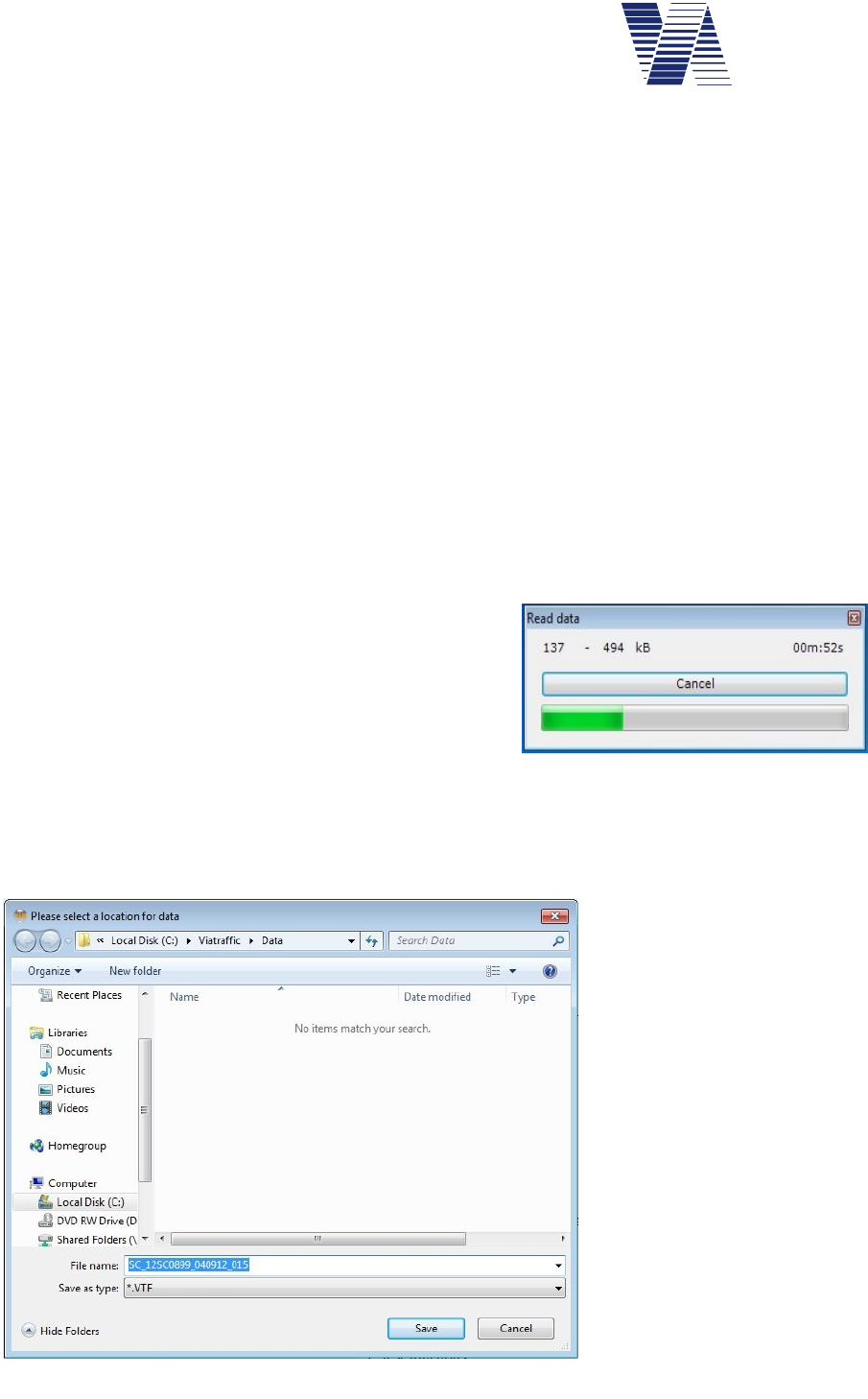
Page 58 of 85
viasis 3003 user manual
via
traffic
controlling
gmbh
6.7 Data memory
The viasis measurement data store is organized as a ring storage, so in case the memory is full
the oldest stored data are overwritten by the newest data. Herewith is guaranteed that the
viasis still keeps the most actual data in case of a data overflow, respectively a too sporadic
measurement data download and deletion.
The viasis is either delivered with 2, 4 or 8 megabyte non volatile flash memory. The herein
stored data have a retention of 20 years minimum according the manufacturer and the memory
cells can be rewritten 100000 times (write/erase cycles), what means a total of 100000 meas-
urements and parameter changes can be done, before statistically a memory failure should
occur.
The measured speed data stored as data blocks with 10 byte length in the memory. Therefore
the storage capacity (minus some bytes for parameter and log protocol) is depending on the
storage size of 2, 4 or 8 MB finally 212160, 425125 or 842952 measurement data blocks. This
is equivalent at a radar range of 120 meter and an average vehicle speed of 50 km/h about
36833, 73806 or 146345 vehicles.
The measurement data store should be deleted after a data download in order to keep the
amount of read data and the data transfer times small.
6.7.1 Read measurement data
For the download of stored measurement data of the
viasis you can use the program viagraph delivered on
CDROM, see chapter 6.1.3 or the ViaApp for
Android Smartphones, see chapter 6.1.1.
In order to start the data download with viagraph the
data connection to the viasis must have been established successfully, see also illustration 11.
Click on the button „Read data“ and the data transfer progress appears, but maybe just for a
glimpse depending on the number of data, see illustration 48.
Next the dialogue to save the
data in a file appears, see il-
lustration 49.
You may change or extend
the proposed file name. In
order to keep a good over-
view over numerous data files
you may e. g. add the meas-
urement location to serial
number and download date
already given in the filename.
With a click on the “Save”
button store the data to your
computer’s hard disk drive.
Illustration 48
Illustration 49: Save data file
Page 59 of 85
viasis 3003 user manual
via
traffic
controlling
gmbh
Select whether you want to delete the measurement data in
the viasis or not, see also illustration 50.
Also in case the viasis measurement data storage is empty a
file with the file name extension *.VTF (“via traffic format) is
created. The file includes the protocol with event and error
messages, the current parameter setting of the system and
eventually GPS position data.
6.7.2 Checking stored measurement data
A check how much and which measurement data are stored in the viasis you can make by en-
tering 1for “Transmit stored data” in the main menu, see also illustration 11.
If no values are stored the viasis returns immediately back to the main menu, otherwise it re-
ports the number of stored speed values:
Number of values = 21233
It follows the question:
Send data (y/n)?
If you enter y the measurement data are send to the terminal, always 25 lines before you are
prompted to continue with <return>:
25;16.12.11;16:52:10
-32;16.12.11;16:52:12
44;16.12.11;16:52:33
38;16.12.11;16:52:35 ...
<Continue with return>
Per line one speed value optional headed by a minus sign indicating leaving vehicle detection,
with date and time, and separated by semicolons is send. If you press any key other as <return>
the output is ended.
After the data output or if you entered n for Send Data (y/n)? following message appears:
Delete data (y/n)?
If you enter j for yes in the terminal all data are deleted, if N for no is given the current meas-
urement is continued. In case the ring data storage is full the oldest data are overwritten by the
actual data.
Illustration 50

Page 60 of 85
viasis 3003 user manual
via
traffic
controlling
gmbh
6.8 Test functions
The test functions menu is shown if you enter 3in the main menu, see also illustration 11 .
Test functions:
1. LED display
2. Flash memory
3. Real time clock
4. Main battery
5. Simulation
6. Light sensor
7. Back
Your choice 1...7?
The test LED-display shows first „19.9“ on the numeric LED display in the LED base color,
then if equipped in the second LED color and if defined in the last optional mixed LED color
with rising brightness in 1%, 2%, 4%, 8%, 16%, 32%, 64% and 100% of the maximal bright-
ness each time for 1,5 seconds. The current value of the LED brightness is also transferred via
data connection to a terminal.
If the LED mixed color is defined „124“ is displayed in varying color balances, afterwards
„124“ is shown in blinking mode in the installed LED colors.
For the following LED display up- and down count test the start and end count value is taken
from the set minimal- and maximal speed displayed parameters defined in parameter set 1,
see chapter 6.3.4.2. Each count value is shown ¾ seconds on the numeric LED speed display.
Further the thresholds for blinking LED display, LED color change and LED mixed color, as
well as for the integrated warning symbols defined in parameter set 1 are recognized for the
equivalent display. Optional installed extensions see chapter 6.3.6, are activated during the up-
and down count test depending if their on/off threshold is exceeded by the count value, or not.
The Flash memory test indicates the installed memory size first:
4 MB Flash installed
The flash memory test destructs stored measurement data and the event protocol, therefore
follows the question:
All data will be deleted
Continue (y/n)?
If you perform the test the proper function of all memory cells is checked by erasing and re-
writing the cell contents:
Erase Page: 4096 ok
Write Page: 4096 ok
The flash memory cells (bits) are organized in so called pages (256, 512 or 1024 bytes of 8
bits). In case of an error the test stops at the erroneous page and the error is reported. Else the
proper memory function is confirmed with ok after the last page was tested.
The test of the Real time clock includes beside the output of date and time a compare test be-
tween a microcontroller and a real time clock time, generated from their crystal oscillator
frequencies. Is the compare time difference smaller than 50 ppm (parts per million), equivalent

Page 61 of 85
viasis 3003 user manual
via
traffic
controlling
gmbh
to an error of less than about 30 seconds per week, the message „RTC ok!“ is send, otherwise
the error is reported in ppm units.
The Main battery test allows the measurement of the lead-gel accumulator voltage and estima-
tion about its charge condition. The measurement is made in contrary to the battery test during
power on initialization without load, that means without active LED display of „188“ and can
be initiated therefore also remotely by a GSM modem. The result is given with 0,1 Volt resolu-
tion between 10,7 and 13,8 Volt (17 Ah accumulator discharge and full charge voltage levels).
The test Simulation is useful in order to check the numeric LED speed display but also for a
functional test of installed system extensions, as additional text displays, switches like opto-
couplers, relays or warn lights at a simulated vehicle, without the need to install and measure
on a road site with vehicle traffic. Further the made parameter settings defined in the parameter
sets, resp. their effects on the behavior of the numeric LED display can be simply tested.
After the test is called you are asked to enter a test speed and the number of the parameter set,
whose parameters shall be recognized for the simulation:
Test speed=51
Parameter set=1
<Quit with return>
The test speed value is compared with the speed threshold parameters defined in the parameter
set, resp. the threshold parameters of the Settings menu and the submenus Thresholds Exten-
sions and Speed display options, for the numeric LED display, the integrated LED circle
symbols, optional extensions and they are activated accordingly.
Only if the test speed in the range between set minimal and maximal speed displayed, see chap-
ter 6.3.4.2 the test speed is shown on the numeric LED speed display. By pressing the
<return> key the LED display and all system extensions are reset and deactivated.
The environment Light sensor, which measures the brightness of the environment, delivers for
a functional check a numerical result:
<Quit with Return>
Light sensor: 955
The result drops in bright sun light down to zero. In dusk, dawn and darkness the given results
are high and tend up to the maximal value 1023. In case the sensor value does not change de-
spite illumination e. g. with a torch or by dark covering, it is defective. The position of the light
sensor in the LED display board is approximately in the middle, right aside the hundred digit.
6.9 Data evaluation
The evaluation of measured speed data is done with the delivered software viagraph. The in-
stallation of the evaluation program viagraph is already described in chapter 6.1.3.
A detailed description of the evaluations you will find in the online help of the viagraph pro-
gram in the menu Help – User Manual1.
1 In order to read the help documents you need to install Adobe Acrobat Reader Version 3 or higher. In the internet you will
find Adobes website with http://www.adobe.com/.
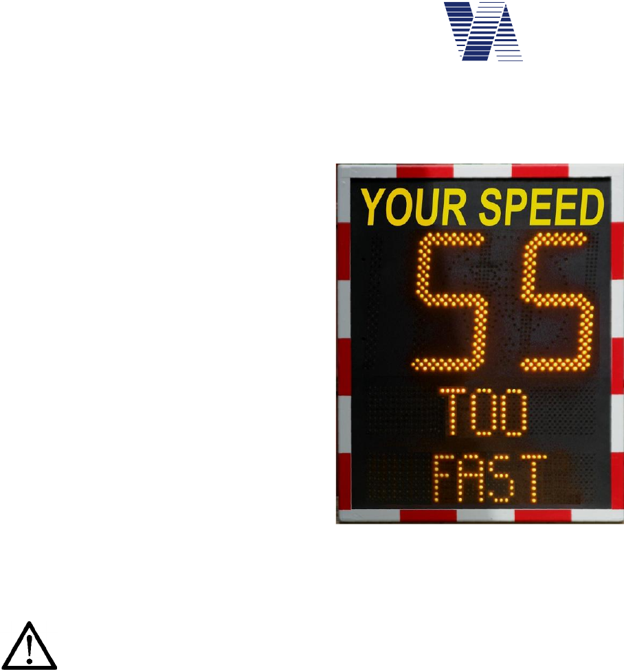
Page 62 of 85
viasis 3003 user manual
via
traffic
controlling
gmbh
6.10 Viasis PLUS display
The add-on display board of the viasis PLUS is in general a two line LED full matrix with own
separate microcontroller with the „Viamatrix“ firmware and a flash memory for the display
text, bitmap graphics and display parameters.
The following description shows how configure
the viasis PLUS by using the viagraph input
window, which is reached by a click on the Ma-
trix button, see illustration 11.
The viasis PLUS display can also be completely
configured by using any terminal software and
the Viamatrix menu system, which is called by
entering <ESC> in the viasis main menu:
Viamatrix menu
1. Text messages
2. User character bitmaps
3. Test functions
4. Parameter
5. Information
6. Back
Select 1 .. 6
From the Viamatrix menu you get back to the viasis menu if you enter ‚6’ for Back.
Attention: Before you close a communication connection and if you used the
Viamatrix menu before - return always to the viasis menu. Otherwise the
Viamatrix program will wait for further menu insertions and will not show
any matrix message until you returned to the viasis menu.
The Viamatrix program has an input menu timeout of 30 seconds until it returns automatically
back to the next upper menu level or resp. to the viasis menu, what makes the “forgot to re-
turn” problem less grave. But depending on the Viamatrix menu level where closed the
connection it still may need several minutes until matrix messages are given again.
The Viamatrix software Test functions and the Information menu are not supported by
viagraph and can be reached therefore only by the menu system.
As the viasis parameter settings the matrix display pages, bitmaps and parameters can be set
offline if you click on the menu Extra – Matrix – viasis PLUS in the viagraph start window,
see illustration 32. Together with the viasis parameter settings a file can be created (see chapter
6.2.4.1) and stored on an USB flash stick for a later upload in the viasis.
The speed thresholds for the activation of the matrix display pages are part of the viasis param-
eter sets, see also chapter 6.3.6.5.
Illustration 51: Viasis PLUS
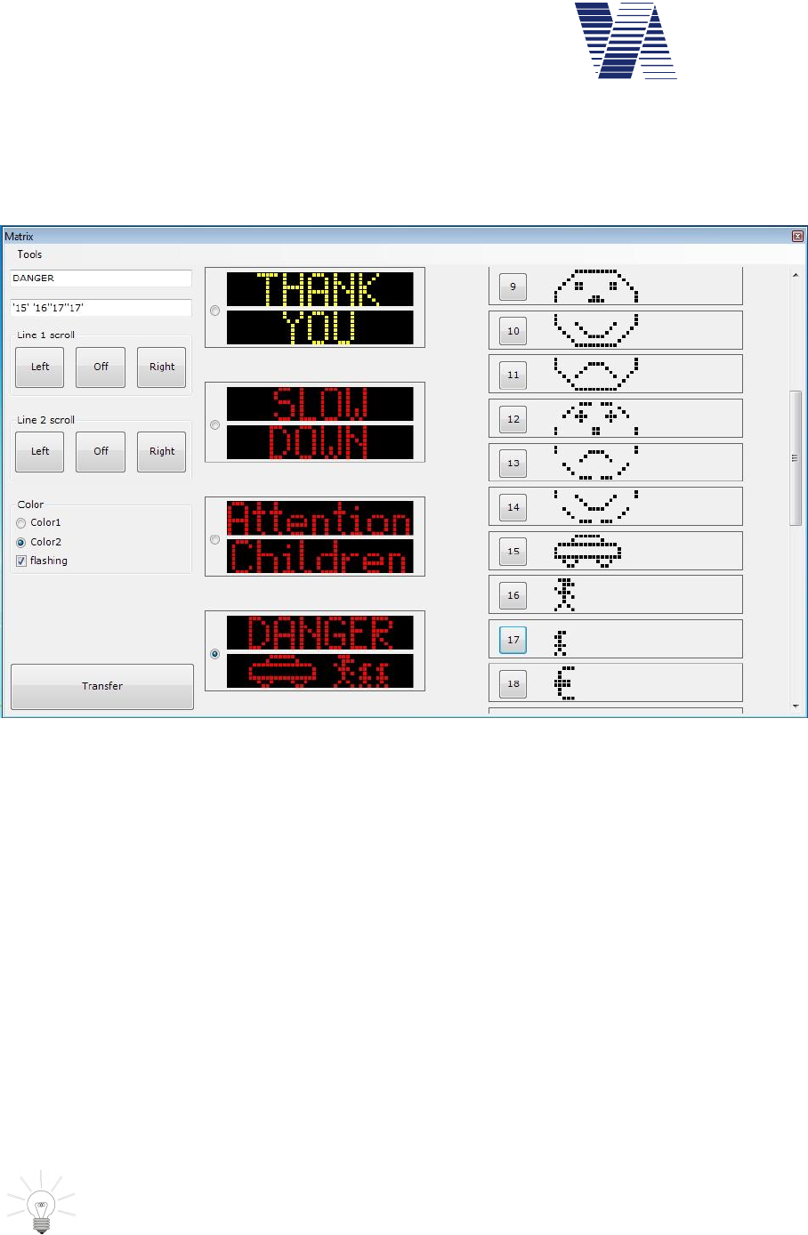
Page 63 of 85
viasis 3003 user manual
via
traffic
controlling
gmbh
6.10.1 Viasis PLUS matrix editor – display pages
After a mouse click to the viasis PLUS Matrix button in the viagraph connection window
(illustration 11) the matrix editor appears and in case the viasis is directly connected with the
current settings:
Illustration 52: Matrix editor main window
The left part of the window is used to edit the LED display pages, each consists of two text
lines. Which page is currently enabled for editing is selected with the check boxes in the middle
column showing the current line contents, see illustration 52.
The two white input lines in the upper left corner of the window are used to enter the needed
display text or symbols. Legal are all printable 7 bit ASCII characters, what means letters, dig-
its and most punctuation marks, except quotation marks (“), which are used to label bitmaps
and placeholders in the text.
Below the lines in the group field Line 1 scroll and Line 2 scroll determine the buttons Left,
Off and Right, if the line text is displayed static or if the text is scrolled through the matrix line
to the right or to the left.
In the group field Color you can define for a two color viasis PLUS matrix, which LED color
is shown and if the text is shown permanently or in a flashing mode.
The black back grounded output fields in the middle column of the windows show how the
text lines will be later displayed on the viasis PLUS LED matrix.
The entered text will be displayed centered in the matrix display. If you need a left-
or right bound display add spaces to the right or left of the text.
Before you close the matrix editor, respectively if you modified all display pages as you wanted
send them to the viasis with the Transfer button otherwise all changes are lost.
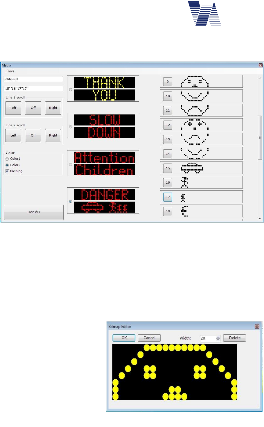
Page 64 of 85
viasis 3003 user manual
via
traffic
controlling
gmbh
6.10.2 Viasis PLUS matrix editor – bitmaps
Beside text the LED matrix can also show so called bitmap graphic. In the right column of the
matrix editor window up to 31 bitmap graphic characters can be defined:
As bitmaps also country specific special characters, as Umlauts, apostrophic characters, etc.,
can be defined. By a click on the number button left of the bitmap the character or the graphic
is placed in the active line, respectively in its text at the current cursor position, see also illus-
tration 53, Bitmap 17.
In the page line the bitmap is placed by its bitmap number, delimited by apostrophes (e. g.
’17’), therefore the use of apostrophes in the text is not allowed.
In order to edit or create new bitmaps double click with the mouse the bitmap picture behind
the number button and the bitmap editor will appear.
6.10.3 Bitmap editor
A pixel (LED) is activated / deac-
tivated with a left/right mouse click
in the bitmap editor. With the but-
ton Delete all pixel are cleared.
Before you start editing the bitmap
set the width of your bitmap, resp.
the number of needed LED col-
umns with Width button. The max-
imal width of the bitmap is the ma-
trix column width, which can be
found in the Viamatrix menu In-
formation.
Illustration 53: bitmap column at right side of the matrix editor
Illustration 54: Bitmap editor
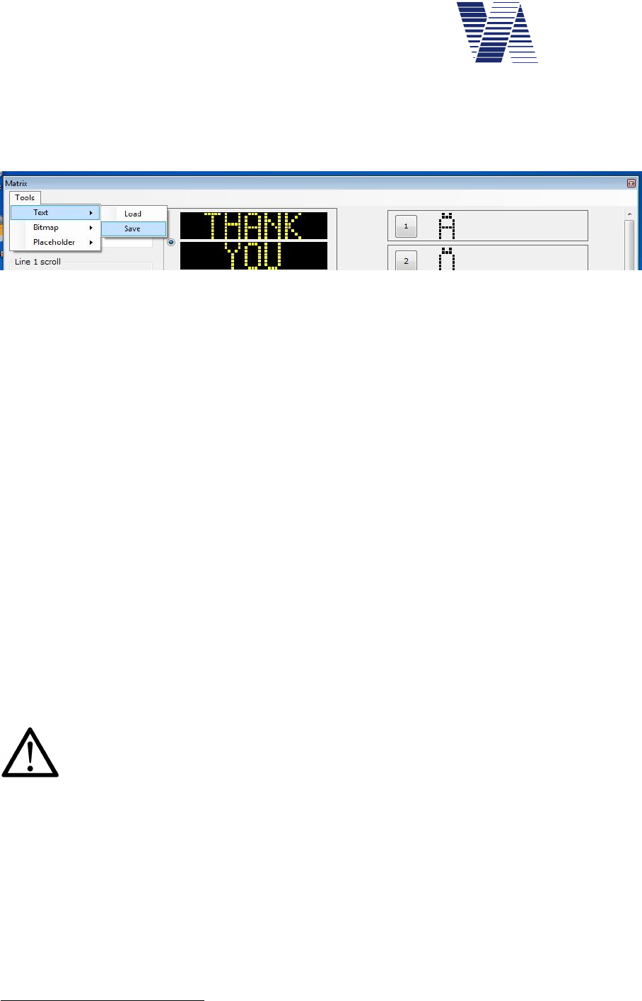
Page 65 of 85
viasis 3003 user manual
via
traffic
controlling
gmbh
6.10.4 Matrix editor menu Tools
In the matrix editor menu Tools – Text you will find the menu items Load and Save. With
Save you can store edited display pages on your computer hard disk in a text file (*.txt), with
Load you can load already saved display page text files.
Illustration 55: Matrix editor tools menu
If you click one of the Text menu items the Windows standard dialogues for “file save as”,
resp. “file open” will appear. Besides the text also edited bitmaps can be stored from or loaded
into the matrix editor by the menus Tools – Bitmap – Load and Save.
Predefined placeholder like date1, time in short format (hh:mm) or long format (hh:mm:ss) can
be inserted like bitmaps in the lines of the display pages, by a mouse click to the wished line
position and hereafter by a click to the menu Tools – Placeholder with the selection of Time1,
Time2, Date or Placeholder. Within the display page lines the placeholders are shown as
apostrophe delimited numbers, which start at ‘127’ (short time format), similar to the bitmaps
(‘1’ – ‘31’). The value or content of placeholders are determined or calculated just before they
are displayed.
Placeholders for time and date can be used for example together with a permanent shown text
page and a 230V net supplied viasis, see also chapter 6.11. Placeholders are further used in
special software which displays calculated money or point penalties depending on the measured
over speeding.
6.10.5 Permanent text page
The viasis PLUS offers the possibility to define a Permanent shown page, that means a dis-
play page shown if no other page is activated due to vehicle detection above the set speed
thresholds.
Be aware: The energy consumption of a permanent shown LED text in compare to the
short time activated, switched text due to vehicle detections, is very high and therefore
only appropriate for 230V mains supplied viasis PLUS. For viasis PLUS with 12V ac-
cumulator is this no option due to the strong reduction of operating time.
For the configuration of a permanent text page proceed as follows:
-In the Viamatrix menu Parameter – Number of text pages, see menu chapter 6.10, rise the
number from 4 to 5.
-In the Viamatrix menu Parameter – Permanent text page enter page number 5. Permanent
text page 0 means deactivated.
-Return to the viasis main menu
1 The time and date clock of the Viamatrix, whose values appear in the matrix lines, are loaded from the viasis
real time clock (RTC) at power on. So changes at the viasis time and date settings, see chapter 6.5.3 get valid
on the matrix after the next power on.
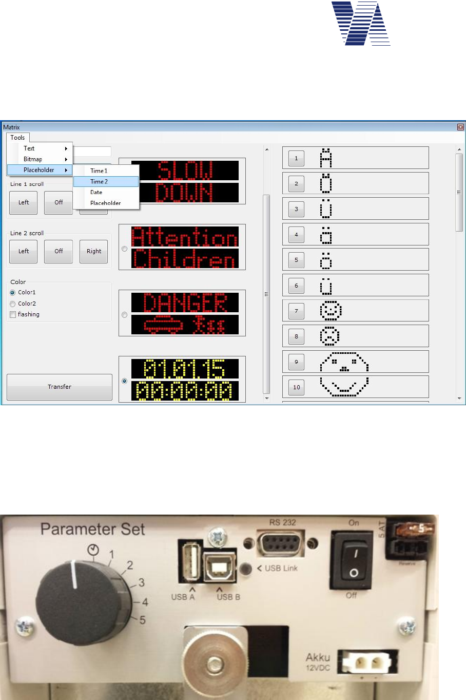
Page 66 of 85
viasis 3003 user manual
via
traffic
controlling
gmbh
If you click now the Matrix button in the viagraph connection window again the new 5. Dis-
play page gets visible if you scroll down with the scrollbar of the middle display column.
Together with the already set placeholders for date and time the permanent 5th text page looks
like in the matrix editor as follows:
Illustration 56: Matrix editor with date and time placeholder in permanent display page
6.11 Select switch option
For the selection of the display parameters the viasis can be optionally delivered with a rotary
turn switch. The turn switch is located in the accumulator box on the control unit board; please
see following illustration 57 below.
Illustration 57: Select switch parameter sets

Page 67 of 85
viasis 3003 user manual
via
traffic
controlling
gmbh
If the select switch is in position of the clock symbol the viasis works in normal mode. This
means the display parameters of the parameter sets 1 to 5 are activated by the time settings of
their weekly calendar.
In case the turn switch is in position 1 to 5 the display parameters of the selected parameter set
(see also chapter 6.3.1) are permanently active.
If the viasis is used at various, changing measurement locations with differing local speed lim-
its, the switch offers the possibility to change quickly the display parameters to appropriate
values of an another parameter set.
7 Technical and physical properties
7.1 Distance range
The detection distance range of all microwave detectors depends to a large extend to reflection
properties of the measured objects and interference properties of the near surrounding.
In common is valid:
As bigger, planer and orthogonal to the microwave beam axis the reflection surface is,
as longer is the distance range.
As less absorbing and scattering the reflection surface, as longer is the distance range.
As more other objects are in measurement beam, as shorter is the distance range (dif-
fraction scattering and foliage losses, shadow losses and so on).
Practically following factors have a reducing effect to the distance range:
High up to the edge of the driveway leading buildings, trees, poles, parked cars and
containers, which hamper the „free sight“ of the detector and/or lead to strong scatter-
ing losses.
Influence through weather, rain and snow lead to absorption losses of the radar
„Blinding of the detector“ through other moving objects as tree branches, persons,
resp. a reduction of the detection range by a too far in the leaving traffic directed radar
beam, see also chapter 5.2.
The above mentioned negative influences have practically a much smaller meaning than it may
seem now, but it makes clear that the reason for a too small distance range is only in rare cases
a deficient microwave detector.
In the free field the radar unit has a typical distance range of more than 120 m for genuine pas-
senger cars. Each viasis is tested before delivery regarding a sufficient distance range. For
trucks the distance range is about 50% higher due to the larger reflection front surface, for
motorcycles it is reduced to 50% and less.
The distance from where the numeric LED display can be read due to the chosen digit size is
also higher than 120 meter.
The highest distance range has a detector mounted in a height of 2 up to 3 meter to the hous-
ing bottom side. This offset from the ground results from the practically necessary small
inclination of the microwave antenna inside the display housing.

Page 68 of 85
viasis 3003 user manual
via
traffic
controlling
gmbh
7.2 Measurement angle
The angle between detector beam axis and the movement axis of the detected vehicles has de-
cisive influence on the measured speed. Microwave detectors and all on the physical „Doppler“
principle based measurement systems (some laser, most infrared and ultrasonic) do not meas-
ure the absolute speed of a vehicle. They measure the relative speed or exactly the angular
speed vector component of a vehicle moving towards the radar beam axis.
This is expressed by following formula:
vmeasure = vabsolute x cos with : measuring angle
The ideal measurement angle is 0°, this means vmeasure = vabsolute and the movement axis and the
radar beam axis are identical in this case.
In practice the system board can only be mounted laterally, besides the driveway. But you
don’t get a measurement error outside the specified accuracy, if you are aware the limits of the
measurement angle (see chapter 5.2).
Please notice the following:
A too large measurement angle can only have a too small speed value as result!
Up to a measurement angle of 4° (equal to which direction) the relative speed meas-
ured by the detector and the absolute speed are the same through the rounding of
the not displayed digits.
7.3 Accuracy
The accuracy of the speed value is:
2% and 1 digit, for the whole measurement range
Herewith the accuracy is better than specified for repressive velocity measurement systems in
the German „Eichordnung“ of the „Physikalisch-Technische Bundesanstalt“ ( 3% for v > 100
km/h and 3 km/h for v < 100 km/h).
Despite this fact, this system is not used in Germany for repressive measurements, because it is
not equipped with a electronic calibration circuitry, what is claimed by the „Eichordnung“.
Also in future we won’t design the system in this way, because the pedagogical intention of
this system for visual speed indication would be mislead.
7.4 Display field and visibility
The display field consists of the 300 mm high LED digits and the 190 mm high digits of the
integrated warning symbols. The chosen letter sizes guarantee readability above 100 Meter.
The angle of readability of the LED digits is with 15° sufficiently high to be seen by the vehicle
drivers with full brightness also in bright sunlight. However for spectators looking from aside
the LED display just seem to glow depending on the viewing angle and may even disappear in
bright sunlight (similar to the fiber optic signs on highways). In common the visibility decreases
for LED with rising brightness of the environment a little bit.
A „phantom light mask“ is placed in front of the LED, which suppress a seemingly glowing of
the LED to a large extent when they reflect the sun light.

Page 69 of 85
viasis 3003 user manual
via
traffic
controlling
gmbh
To avoid blinding effects of the vehicle drivers, especially during night-time or covered sky, the
system is equipped with an environment light sensor and a LED brightness control with a reso-
lution of 0,5% of the maximal brightness.
7.5 Display frequency
The update frequency of numeric LED display is identical with the measurement frequency of
the radar detector. As long a moving object is detected its speed is updated all 1,5 seconds on
the numeric LED display. The last measured speed value is hold for about 3 seconds on the
LED display.
The display cycle of 1,5 s has emerged as ideal in comprehensive tests. The driver perceives
the display frequency after interviews not as too high and therewith not too flurry. In contra-
diction, the driver sees the displayed speed from a quite far distance, realizes that he is over
speeding and slows down. On the display he (and the spectator) gets as a direct feedback the
reduced speed displayed, let’s say as reward and the driver passes the display with the correct
speed. Characteristic is that the driver has enough time to develop a feeling for the right speed.
Hereby is the high distance range the decisive advantage. At a shorter distance range, the driv-
er gets his over speeding displayed, but there is no time for a „dialogue“ between driver and
display. The driver has no time to react and the feedback - the reward is missing as well.
7.6 Power supply and operating time
7.6.1 Accumulator version
For the power supply a 12 Volt lead gel battery pack with a capacity of 17 Ah is installed in a
small plastic box on the backside of the housing.
The viasis has a discharge protection for the accumulator to prevent irreversible chemical de-
composition of the battery electrolyte due to long time discharge below 10,7 Volt. The
protection circuit disconnects the viasis from the battery when the voltage drops below 10,7
Volt and (re-)connects it when the battery voltage is 11,3 Volt minimum.
The operating time of the viasis relies essentially on the number of displayed speed values, the
environment brightness and self evidently on the battery capacity. In bright sunlight the power
consumption due to maximum LED brightness is maximal 11 Watt when displaying “188” on
the numeric LED display. By night with minimum LED brightness level the consumption is less
than 1 Watt for displaying “188”.
So the operating time of the viasis 3003 is at a display rate (relation between display on and off
time) of 25%, with calculated 16 day and 8 night hours, for the 17 Ah battery about two
weeks.
7.6.2 Mains supply 115/230 Volt AC version
Attention: For viasis delivered as 115/230 Volt AC version do not remove or
disconnected the buffer battery. The buffer battery delivers peak currents,
filters mains distortions and ensures that the voltage level of the AC/DC
power supply does not rise to illegal over voltage levels and blows the system fuses.
Additionally the buffer battery allows the operation of the viasis at timely powered light poles
and ensures an operation for several days if the mains line is switched off.
In rare cases with the viasis connected to a heavily distorted mains supply it might be necessary
to install a harmonic filter to ensure proper system operation.

Page 70 of 85
viasis 3003 user manual
via
traffic
controlling
gmbh
Attention: Work at 115V/230V installations must be generally carried out by
electro-technically trained personnel or specialized companies, according to
the relevant technical regulations
7.6.3 Viasis with photovoltaic solar support
Attention: Never operate the Viasis with solar panel and disconnected main
battery. Always connect the battery first before the solar panel.
The solar charge module needs a buffer battery for proper operation and the clamp
voltage of the solar module may rise in bright sun light to a destructive level for the electronic
without connected lead-acid gel battery.
7.7 Operating temperature
The semiconductor components used in our production including the LED’s are specified for
industrial applications. That means an operating temperature range from -40 to +85 Celsius
is guaranteed by the manufacturer.
The microwave transceiver is specified for an operating temperature range from -20 to +70
Celsius. Outside these limits the manufacturers give no guarantee for a faultless function.
7.8 Water protection
The industrial housing protection class is IP64 (compare EN 60529). IP64 means that the sys-
tem is protected against intrusion of dust and the housing protected against water splashing
from any direction. The housing is in any case sealed against rain water.
Another thing is the problem of humidity, because the housing has two small drillings (Ø 2mm)
at the housing bottom for pressure balancing. Strong temperature differences between a hous-
ing interior and the surrounding produce a low pressure situation in the housing interior. Slow
pressure compensation with the intrusion of humid environmental air may settle down moisture
on the surface of the interior housing walls, also at the inner side of the front pane. The hous-
ing has the two drill holes in the frame on the bottom side for pressure balancing and the drain
of condensing water.
7.9 Radio wave interference
Through the use of stereo-channel Doppler transceiver (radio wave transmitter and receiver)
and an appropriate measure procedure with steady signal supervision the display of speed val-
ues caused by interfering radio waves of other systems can be excluded.
If the interfering signal is much stronger than the received radar signal of the viasis then the
system stops operation. In such rare case you need to change the measurement place.
Page 71 of 85
viasis 3003 user manual
via
traffic
controlling
gmbh
8 Maintenance
8.1 Cleaning the front window pane
Attention: To clean a dirty front window pane use always a liquid antistatic
detergent or an antistatic cleansing towel!
Otherwise the transparent plastic front pane can be electrostatic charged up to sev-
eral kilovolts (frictional electricity) especially when using dry paper or synthetic textile towels.
The discharge pulse may destroy the semiconductor components in the microwave transceiver.
A damaged or destroyed microwave transceiver reduces the measurement distance range or
leads to a complete failure of the measurement display.
8.2 Charging and testing the lead acid battery
The battery is discharged, if the voltage level drops below 10,7 Volt. The battery is separated
below this level through the integrated low level discharge protection. Recharge the empty
battery immediately to avoid irreversible chemical destruction.
Attention: The batteries shall be stored only in loaded condition at dry loca-
tions!
The self-discharging of our delivered batteries is with 0,1% (at 20°C) of the loaded
capacity per day very low, so that charged batteries can be stored also for longer times (½
year) without any problems.
The battery voltage level can be checked under load condition at power on („188“ is displayed
and the battery voltage value follows) and when you connect a laptop or PC and use the test
function „main battery“, see also chapter 6.8, but without load. Is the battery voltage level
below 11,3 Volt the viasis will not start operation.
For the battery loading you should use our automatic battery charger, which stops loading at
the high level battery voltage of about 13,8 Volt. If you use a battery charger with no overload
protection, it might destroy the battery chemically if a voltage level of 13,8 Volt is exceeded.
Reverse connection of batteries and charger are impossible with the viasis battery connectors
which allow a plug in the coupling only in the correct way.
Attention, if you use third party chargers: When connecting the cables of the
battery, take care of the right polarity! Connect the black minus pole of the
charger to the black minus pole of the battery and the red plus pole of the
charger to the red plus pole of the battery. Lead-acid gel batteries can be charged reverse
and herewith destroyed. Additionally the next connection to the viasis will cause a short
circuit and blow the fuse in such a case.
The time to load a completely empty 17 Ah battery with our battery chargers (load currents 2
Ampere) is approximately 10 hours to 90% of the battery capacity. The time to load the bat-
tery to full capacity (charger LED load control extinguishes) can be much longer.
Page 72 of 85
viasis 3003 user manual
via
traffic
controlling
gmbh
8.3 Changing the battery
To withdraw the battery unfasten the cover brackets and open the cover of the battery box,
placed on the backside of the viasis display system.
Remove the plug of the battery cable from the control panel socket, see illustration 8. Untight-
en the knurled nut above the turn bolt, turn the bolt aside and take out the battery. To install
the battery proceed in reverse order.
Attention: In case of two or more batteries – disconnect all empty batteries
first before reconnecting the charged batteries. Otherwise the fuse(s) might
be blown, due to the high current flow between empty and full batteries.
When you close the battery box cover take care not to press or cut the battery cable
wires.
8.4 Changing the fuse
In order to change the main fuse open the cover of the battery housing on the backside of the
display system. The main fuse holder is placed in the upper right corner of the control panel.
Replace the fuse with a mini 5 Ampere inert vehicle plug in type fuse.
Attention: Replace the fuse by the same type. Using fuses with higher cur-
rent values means in worst case a burned down system, if an electric
internal short circuit occurs!
8.5 Serial RS232 interface connector
The serial RS232 D-SUB socket is placed on the control panel in the battery box.
Only data receive and send line, signal ground line and shielding are connected by the interface
cable. This means no hardware control (RTS, CTS, ....) for the data flow is supported.
The pin connections (scheme see table below) at the 9 pole D-SUB connector of the interface
cable comply to the RS232C interface standard, used in almost every personal computer, lap-
top or palmtop. Should the communication be impossible even after correct setting of the
interface parameter and the right serial port chosen, check the interface description of your
computer manual. It might be necessary to exchange the RxD and TxD line at the D-SUB con-
nector.
If you have a computer with 25 pole DSUB serial interface connector, a ready-made adapter to
the 9 pole DSUB connector of the interface cable can be purchased in computer trade shops or
from us.
pin signal description
2TxD viasis transmit data
3RxD viasis receive data
5GND Ground

Page 73 of 85
viasis 3003 user manual
via
traffic
controlling
gmbh
8.6 Trouble shooting
No „188“ value displayed after power on
Prove connection between battery clamps and control panel connector for
intermittent cable wires. Are the connector/socket contacts deformed or cor-
roded? Check the main fuse in the battery box. Control the battery voltage –
are 11,3 Volt present at the connectors when connecting the battery?
If you are not successful, you have to send us the system back for repair.
„188” does not disappear after power on
Send us the system back for repair.
„188“ flashes after power on continuously
Reason is probably an old or defective battery, which lost its energy storing capacity. Retry it
with a new battery. If you do not succeed contact us.
No speed value appears during vehicle detection
Has the viasis „free sight“ to the vehicles? Is the viasis straightened correctly (chapter 5
foll.)?
Are other high frequency wave radiating installations like high voltage lines, radar or radio
antennas in the near surrounding?
Is the minimal or maximal displayed speed set correctly (see chapter 6.3.4.2)?
Is the Led display deactivated in the actual valid parameter set (see chapter 6.3.2.1)?
Is the measurement time limited in the time schedule of the currently valid parameter set (see
also chapters 6.3.2 foll.).
Has the sensitivity of the radar been reduced (see chapter 6.3.7)?
If you don’t succeed contact our technical support first.
Car speedometer and display value are not equal
Car speedometers are not calibrated and show a remarkably higher speed than the real physi-
cal speed of a vehicle. To check the accuracy of the measured speed no car speedometer can
be used, except it was calibrated by the manufacturer (what is not done for serial cars).
An exact check of the accuracy must be made with a calibrated reference system (with radar,
laser, infrared or other optical methods) or a police car with calibrated speedometer.
If you have anyhow the impression that the displayed speed value is too low read chapter
5.1, 5.2 and 7.2 first.
If you don’t succeed contact our technical support first.

Page 74 of 85
viasis 3003 user manual
via
traffic
controlling
gmbh
Unmotivated speed values are displayed
Are moving objects in the range of the detector, like crossing traffic, moving branches of
trees, birds, bicycles, pedestrians and so on?
If you don’t find any causes for the malfunction, contact us and send the system back.
The numeric LED display shows characters, which are not numbers
The system has an internal defect, contact us and send it back for repair.
8.7 Transport damages
Packing wrap damaged:
Unpack in presence of the delivering transport driver and let him confirm possible
damages of the display system on the delivery notes.
Packing wrap all right, packing contents damaged:
Inform the hauler immediately and demand for an inventory of the damaged display system, if
possible tell the transport driver to note the damage.
Important: Under all circumstances, to avoid the loss of compensation through the transport
insurance or from the hauler, inform the hauler within 24 hours. The delivered systems have
to remain in the same condition until the examination by the insurance took place.
8.8 Sending back/transport preparation/disposal
Before you send the system for repair contact our support. Sometimes systems do not operate
due to parameter settings or other reasons, often we may also offer a less expensive transport
way. Send parcels with „receiver pays cargo fees“ are not accepted.
Error description:
For a faster treatment of your repair, please write us a short error description and
name us a contact person for possible questions of our side.
Packing wrap:
In order to lessen the risk of transport damages, the system should be send generally
only in a complete original packing set. Every wrapping is usually used for maximal
two ways. Although the cardboards may lose their mechanical stability, the foamed
plastic bodies can be used more often. If you cannot store the packing material we
are ready to take it back.
If the original packing set is fully or partly lost, the empty packing set can be ordered from us
(only complete).
Take-back and disposal of old systems:
We take back and dispose our systems free of cost. We disassemble the systems,
sort the parts and materials, which are recycled or if possible reused. Send parcels
with „receiver pays cargo fees“ are not accepted. Please mark the systems clearly
‘for disposal’.

Page 75 of 85
viasis 3003 user manual
via
traffic
controlling
gmbh
9 Viasis 3003 certification, conformity and compliance
9.1 CE-conformity viasis 3003
CE Declaration of Conformity
in accordance with the EC directives 2014/53/EC (RE) and 2011/65/EC (ROHS)
The manufacturer: Via traffic controlling GmbH
Declares that the product: viasis 3003 (COMPACT, MINI, PLUS, PLUS SMILE)
Intended purpose: Speed measurement system
Type: Radio equipment Equipment class: 1
Complies with the essential requirements of article 3 of the RE (radio equipment) directive, when
used for its intended purpose:
- Health and safety requirements pursuant to article 3.1a, according low voltage directive 2014/35/EU
- Protection requirements concerning electromagnetic compatibility article 3.1b, according electromagnetic
compatibility directive 2014/30/EC
- Air interface of the radio systems pursuant to article 3.2
Harmonized standards applied: Other means of providing conformity with the
EN 60950-1:2006 + A11:2009 + A1:2010 essential requirements (standards, specifications):
EN 55022: 2011-12 EN 62311 (VDE 0848-211): 2008-09
EN 61000-4-2/3/8 : 2009-12/2011-04/2010-11
EN 50293: 2002-02
EN 300440-1(V1.6.1)/-2(V1.4.1): 2010-08
EN 301489-1/-3(V1.9.2/V1.4.1): 2011-09/2002-08
The system complies with directive 2011/65/EC (ROHS – restrictions on the use of hazardous sub-
stances).
Equipment marking:
Address: Via traffic controlling
Campusallee 1
D-51379 Leverkusen
Germany
Place and date: Leverkusen, 26 January 2016
Name and signature: Dipl.-Ing. (FH) J. Geßler
Senior engineer
9.2 Viasis 3003 CE compliance and notification
The viasis 3003 is tested according the applicable EN 300440 and EN 301489 test standards.
A national notification according EC directive 2014/53/EC (RE) is for radio equipment class 1
not necessary, because these radio equipment operates in a EC wide harmonized frequency
band (EC decision 2013/752/EU, band no. 70a, 24.15-24.25 GHz).
The system can be operated and placed on the market in the European Community, including
Switzerland and Norway. Further radio licenses or approvals are not needed within the Euro-
pean Community and further legal limitations are yet not known.
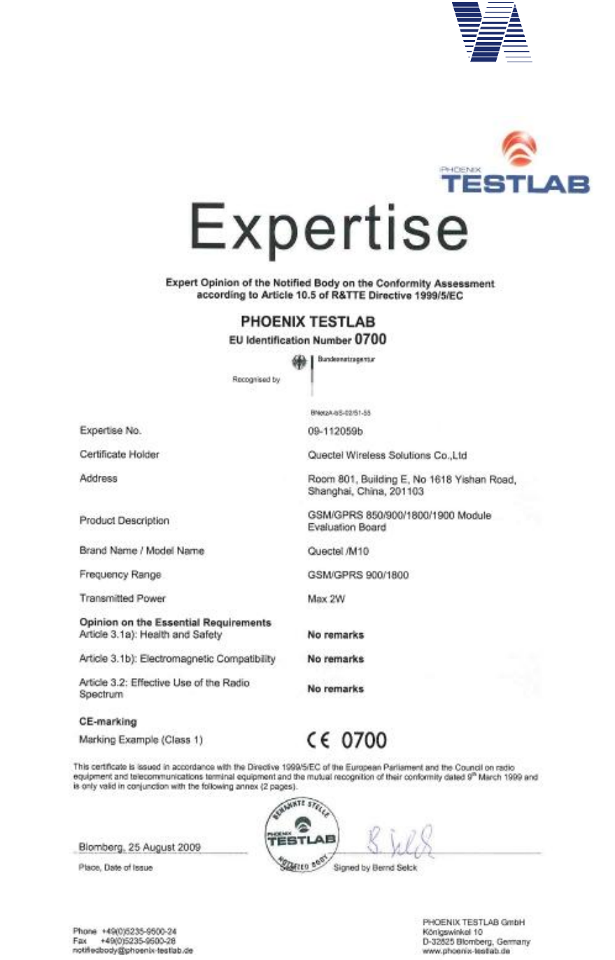

Page 78 of 85
viasis 3003 user manual
via
traffic
controlling
gmbh
9.5 Viasis 3003 FCC and IC compliance
The viasis 3003 speed display with integrated radar transceiver has been tested according FCC
15 rule 15.245 and IC standard RSS-210, issue 9, annex F.
For FCC and IC certification and test reports regarding the contained Bluetooth module Laird
730-SA, please see the delivered CDROM in folder \Compliance\Blutooth_Laird_730-SA.
For FCC and IC certification and test reports regarding the optional contained GSM/GPRS
module Quectel M10, please see the delivered CDROM in folder \Compliance\Quectel_M10.
Notice:
This device complies with Part 15 of the FCC Rules and with Industry Canada li-
cense-exempt RSS standard(s).
Operation is subject to the following two conditions:
(1) this device may not cause harmful interference, and
(2) this device must accept any interference received, including interference that
may cause undesired operation.
Changes or modifications made to this equipment not expressly approved
by Via traffic controlling GmbH may void FCC and IC authorization to
operate this equipment.
NOTE: This equipment has been tested and found to comply with the limits for a
Class A digital device, pursuant to Part 15 of the FCC Rules. These limits are de-
signed to provide reasonable protection against harmful interference when the
equipment is operated in a commercial environment. This equipment generates, us-
es, and can radiate radio frequency energy and, if not installed and used in
accordance with the instruction manual, may cause harmful interference to radio
communications. Operation of this equipment in a residential area is likely to cause
harmful interference in which case the user will be required to correct the interfer-
ence at his own expense.
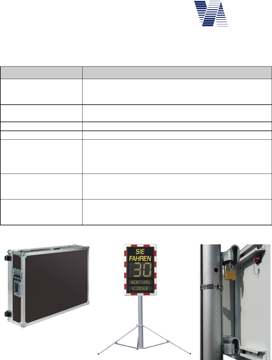
Page 79 of 85
viasis 3003 user manual
via
traffic
controlling
gmbh
10 Annex
10.1 Viasis 3003 list of equipment
Name/ article Description/specification
Transport casing With two transport rolls, 3 solid metal handles, 4 butterfly lock-
ers, outside double profile frame, inside fitting plastic foam, see
also photo 1
USB-RS232 adapter Adapter for the serial connection of RS232 devices to computer
USB interfaces
Spare battery 12V/ 17 Ah 12 Volt, 17 Ah, weight 6 kg
Battery charger 2 A Automatic charger 12 Volt, 2 A, for 17 Ah Accumulator
viasis aluminum tripod Stable tripod collapsible with telescope pole, weight 10 kg, tri-
pod ground diameter up to 2.4m, material eloxated aluminum,
viasis mounting height up to 2.1m, transport measures: 30cm x
32cm x 166cm, see photo 2
viasis steel tripod Robust, collapsible tripod with telescope pole, weight 12 kg,
tripod ground diameter up to 1,7m, viasis mounting height up to
2,2 m.
Pole fixation kit The 2 system holders are hanged-in the pole holder, mounted
with high endurance steel ribbons with special theft protected
closure, see photo 3.
Photo 1: Transport casing
Photo 2: viasis tripod Photo 3: Pole fixation kit

Page 80 of 85
viasis 3003 user manual
via
traffic
controlling
gmbh
10.2 Technical Specifications1 viasis 3003
Doppler-radar: Transmit frequency 24.165 GHz
Emitted output power < 100 mW (EIRP)
Beam width (at 3dB points) 11 horizontal, 17° vertical
Measurement angle < 5
Speed display range 5 ... 199 km/h
Accuracy 2 % 1 digit
Distance range > 120 m
Detection mode uni- or bidirectionnel
Numeric LED
display: AlInGaP High Power LED 2 ½ digits
Exposure angle 15
Colors (EN12368, DIN6163-5) Yellow, 585-597 nm
Red, 613-631 nm
Green 489-508 nm
White (x/y 0.35/0.38)
Brightness reduction (by aging) < 10 %
Lifetime > 10 years
Letter size LED digits 300 mm
Readability > 150 m
Letter size LED digits ca. 1,5 s
Hold time 3 s
Integrated Led warning
symbols: Led circle diameter 300 mm
Digit-/symbol height 190 mm
Readability 120 m
Fixed text: Letter height 100 mm
Readability 80 m
Data memory:Flash FIFO ring store 2/4/8 megabyte
Write cycles/data retention 100000 / 20 years
Serial Data
interfaces: RS232 standard/connector RS232C,V24/DSUB 9 pole socket
Data transfer parameter 8 data-, 1 stop-, no parity
Data transfer speed 115200 Baud
Data output ASCII, 1k xmodem and ymodem
Bluetooth radio modem see chapter 10.2.4
USB host interface/connector USB 2.0, USB-B socket
USB client interface/connector USB 2.0, USB-A socket
Power supply: Rechargeable lead-gel accumulator 12 Volt / 17 Ah
Electrical peak power 11 Watt
Operating time 17 Ah battery 2 weeks
Battery voltage level control 10.8V till 15 V, 0.1 V resolution
Car fuse 5A inert, ISO8820-3 type F
1 Subject to technical change.

Page 81 of 85
viasis 3003 user manual
via
traffic
controlling
gmbh
Real time clock
backup battery: Minimum lifetime 7,5 years
Plug in 3V Lithium button cell CR2430
Housing: W x H x D in mm 640 x 548 x 1851
Weight (without battery) 12 kg
Material frame Aluminum
Front window pane Makrolon
Protection class IP64, see chapter 7.8
Fixation 2 x 35 mm C profile rails
Operating
temperature range: -20 ... +70 Celsius
10.2.1 Supplementary data – viasis PLUS version
Housing: W x H x D in mm 845 x 640 x 1851
Weight without battery 16,5 kg
Power supply: Electrical peak power 18 Watt
Operating time 17 Ah battery 1-2 weeks
LED matrix: uni-/ or bicolor 2 lines with 1/2 x 8 x 48 LED
Line distance 50 mm
Line dimensions W x H in mm 100 x 500
10.2.2 Supplementary data – viasis PLUS SMILE version
Housing: W x H x D in mm 845 x 640 x 1851
Weight without battery 16 kg
Power supply: Electrical peak power 14 Watt
Operating time 17 Ah battery 2 weeks
LED fixed text: Height text > 100 mm
Diameter circle symbols 285 mm
10.2.3 Supplementary data – viasis MINI version
Housing: W x H x D in mm 640 x 425 x 1851
Weight without battery 12 kg
Power supply: Electrical peak power 11 Watt
Operating time 17 Ah battery 2 weeks
Fixed text: Text height 110 mm
1 Housing measures: Width and Height without installations (Handle, hinges,...), depth including battery box

Page 82 of 85
viasis 3003 user manual
via
traffic
controlling
gmbh
10.2.4 Technical Data - Bluetooth modem
Bluetooth modem type Laird BT730-SA (integral ceramic antenna)
Bluetooth standard Version 2.0 / SPP
Bluetooth class I / 18 dBm
Range (free field) > 100m
Data transfer rate > 75 kBaud in y-modem transfer
Current consumption at 12V supply:
- Not connected, standby
- Active connection
- Receive/Transmit operations
0,5 mA
12 mA
22 mA typical
Operation temperature range -40° C to +85° C
Compliance CE, FCC, IC
10.3 Technical data optional components
10.3.1 Technical data – Control panel USB
USB host (computer) connector USB - B socket type
USB client (USB-stick) connector USB - A socket type
USB client supply voltage 5 Volt
USB client supplied current 100 mA
USB standard/specification USB 2.0
10.3.2 Technical data – 115V/230V mains supply
Nominal input voltage 115V~ or 230V~
Minimal/maximal input voltage 90 V~ / 264 V~
Range 50 Hz mains frequency 47Hz to 63Hz
Protection connector plug/-coupling IP67 (dust sealed, waterproof)
Max. current/poles/ground contact code 16 A, 3 pole, 2L+PE, 6h, blue color code
Plug-/coupling standard EN 60309, IEC 60309 (CEE 17)
Page 83 of 85
viasis 3003 user manual
via
traffic
controlling
gmbh
10.3.3 Technical data – solar module
Solar module technology polycrystalline photovoltaic cells
Dimensions in mm 690 x 690 x 36
Nominal power 50 Watt1
Nominal-/Open clamp voltage 12V= / 21,7V=
Weight without/with fixation 6.3kg / 13.3kg
10.3.4 Technical data – low voltage relays
The relay board(s) and connector terminals are placed in an add-on housing on the viasis back
plate. Information to connection schema, cable gland, etc. see manual sisrelais_216_e.pdf. In
total 2 relay boards with 7 relays can be controlled by the viasis.
Maximal assembly per board 7 mono stable changeover contact relays
(SPDT)
Terminal connections 4 x 3 (open, close, common contact)
Max. switched voltage and power 400V~/150V=, 2000VA/192W
Max. switched current 10A~/10A=
Dielectric strength (1 minute) 1 kV/5kV between contacts/contact to coil
Isolation transient over voltages 10000 VAC (for 1.2 x 50µs
Max. on/off switch time 10ms/5ms
Contact material Gold plated silver-alloy
Minimal switch load 10 mA @ 5VDC
Attention:
- Relays shall not be used to switch inductive or capacitive loads,
see chapter 10.3.4. If these loads are switched sparking occurs
while the mechanical contacts are opened or closed, what will
destroy the contacts surface in short time.
- The gold plating of the relays evaporates at high switching pow-
er, afterwards the relay cannot be used to switch small signals
reliably anymore.
10.3.5 Technical Data – MOSFET power transistors
The MOSFET power transistor boards and connector terminals are placed in an add-on hous-
ing on the viasis back plate. Information to connection scheme, cable glands, etc. see manual
sisrelais_216_e.pdf. In total 2 boards with 7 MOSFET high current transistors can be con-
trolled by the viasis.
1 Currently used module type and power may change, please ask.
Page 84 of 85
viasis 3003 user manual
via
traffic
controlling
gmbh
Maximal assembly per board 4 p-ch MOSFET power transistors
Max. switched voltage (UGS @ 25°C) 20 Volt DC
Maximal current (ID @ 25°C) 74 Ampere DC
Maximal switch power (Ptot @ 25°C) 200 Watt
Inner resistance (RDSon) 0,02 Ohm
Switching times (ton/toff) < 200 ns
Switch protection Reverse diode Source-Drain
Hints:
- MOSFET power transistors do not provide galvanic isolation between viasis
electronic and switched load, but have no wear parts as relays have.
- MOSFET power transistors switch inductive and capacitive loads without
being damaged.
- The MOSFET power transistors can additionally be controlled with an envi-
ronment brightness dependent PWM (pulse width modulated) signal. Therefore
they are appropriate for supplementary customer specific external LED dis-
plays.
10.3.6 Technical Data - GSM/GPRS radio module and SIM card slot
Type of radio module Quectel M10
Transmit frequencies quad band 850/900/1800/1900 MHz
Maximal transmit power 2W @ 850/900 MHz, 1W @ 1800/1900 MHz
CSD data transfer speed maximal 14,4 kBaud
GPRS multislot class and mobile station class Slot 12/10/8 / Class B
GPRS data transfer speed maximal 85,6 kBaud (up- and downlink)
Data protocols and -interfaces PPP, TCP/IP, HTTP, FTP, SMS, MMS, FAX
SIM card slot standard Mini-SIM ISO/IEC 7810:2003 – ID-000
CE test and product standards EN301489-7 V1.3.1:2005 (EMC)
EN301489-1 V1.8.1:2008 (EMC)
EN301511 V9.0.2 (GSM radio spectrum)
ETSI TS 151010-1 V1.8.0 (Mobile stations)
EN60950-1 :2001+A11
:2004 (Electr. safety)
Compliance CE, FCC, IC
GSM/GPS combined antenna type Siretta Tango 19
GSM antenna gain 2dBi@ 900 MHz / 1 dBi@1900MHz
Operating temperature range - 45° C to +85°C

Page 85 of 85
viasis 3003 user manual
via
traffic
controlling
gmbh
10.3.7 Technical Data – GPS module
GPS module Quectel L70, L1 band receiver 1575,42 MHz
Power consumption during position fix 20 mA @ 12V (with active GPS antenna)
Position fix time (TTFF) < 35 s (optimal satellite reception)
Position accuracy < 2,5 meter (CEP)
Operating temperature range -45° C to +85°C