Viavi Solutions RKT002-0000 Remote Cellular Test Node/AMP User Manual RCATS Auxiliary Mobile Platform Quick Start Guide

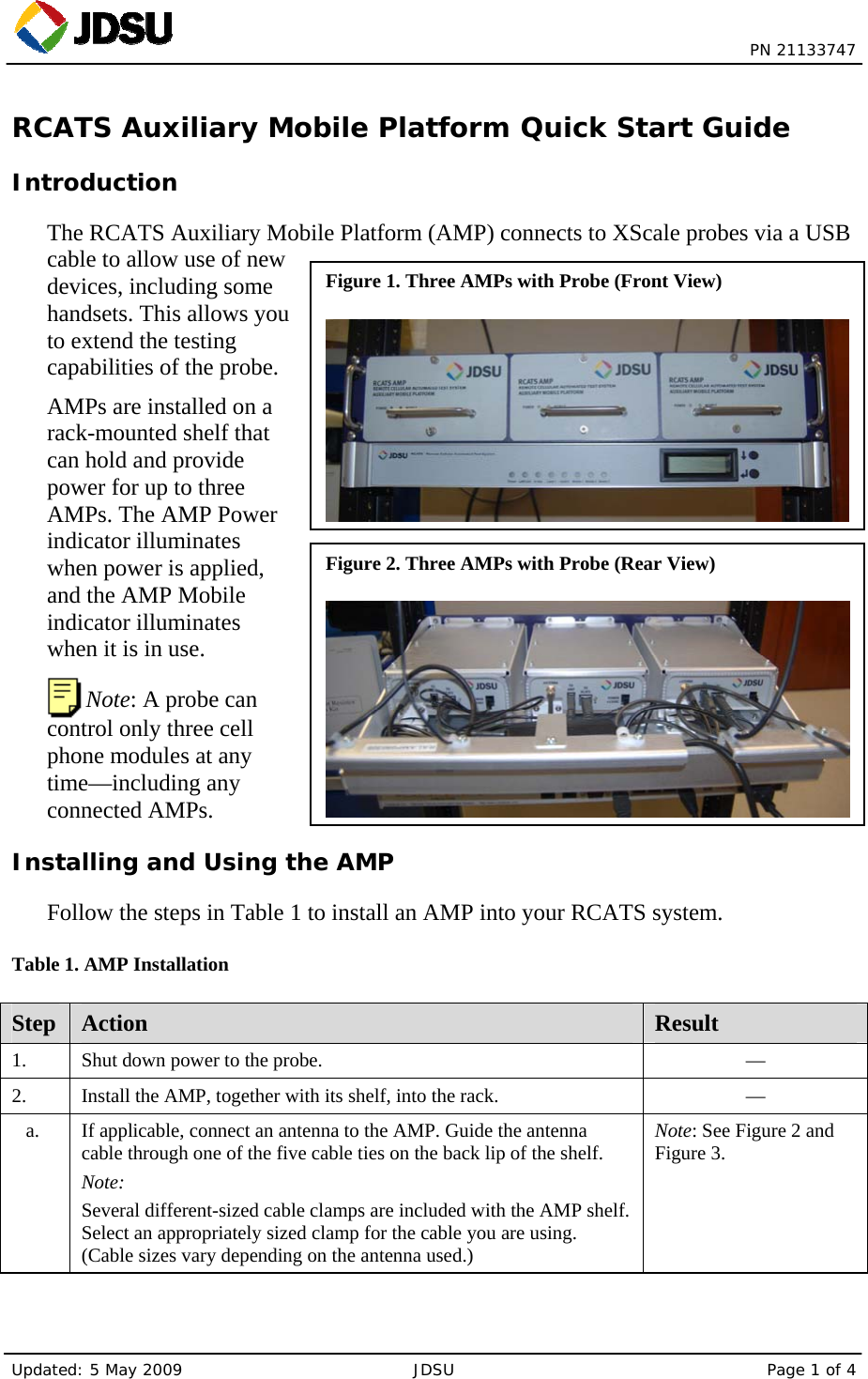
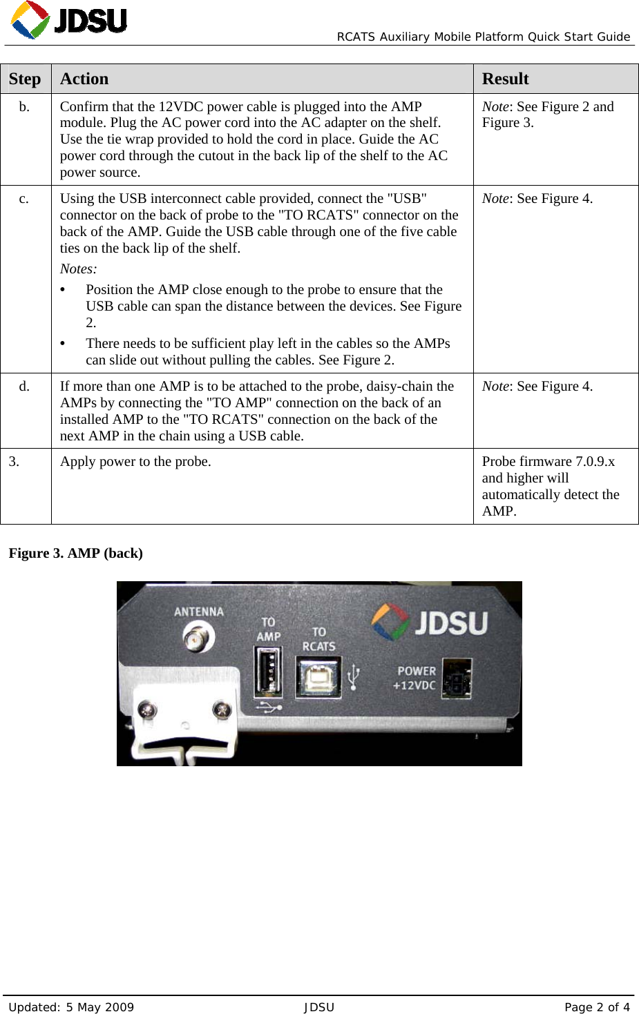
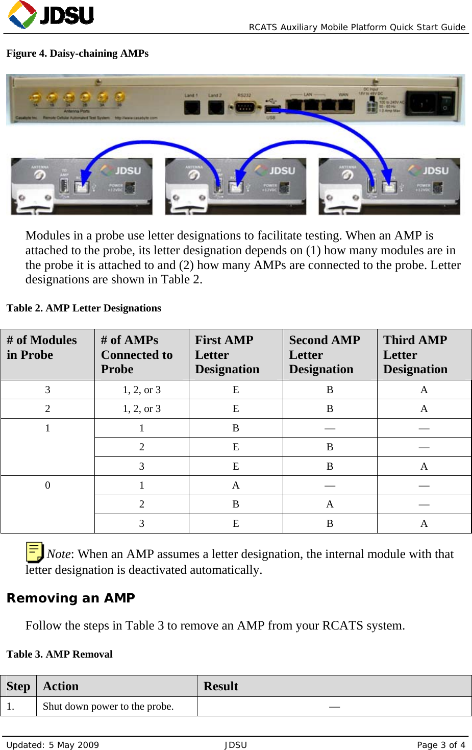
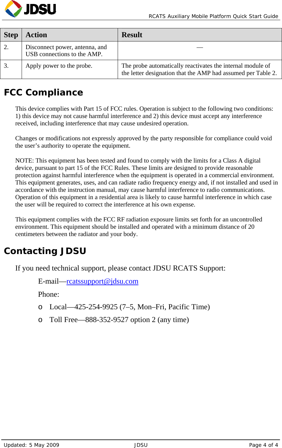
Viavi Solutions Inc. Remote Cellular Test Node/AMP RCATS Auxiliary Mobile Platform Quick Start Guide

User Manual

 PN 21133747 Updated: 5 May 2009  JDSU  Page 1 of 4 Figure 1. Three AMPs with Probe (Front View) Figure 2. Three AMPs with Probe (Rear View) RCATS Auxiliary Mobile Platform Quick Start Guide Introduction The RCATS Auxiliary Mobile Platform (AMP) connects to XScale probes via a USB cable to allow use of new devices, including some handsets. This allows you to extend the testing capabilities of the probe. AMPs are installed on a rack-mounted shelf that can hold and provide power for up to three AMPs. The AMP Power indicator illuminates when power is applied, and the AMP Mobile indicator illuminates when it is in use.  Note: A probe can control only three cell phone modules at any time—including any connected AMPs. Installing and Using the AMP Follow the steps in Table 1 to install an AMP into your RCATS system. Table 1. AMP Installation Step  Action  Result 1.    Shut down power to the probe.  — 2.   Install the AMP, together with its shelf, into the rack.  — a.    If applicable, connect an antenna to the AMP. Guide the antenna cable through one of the five cable ties on the back lip of the shelf. Note: Several different-sized cable clamps are included with the AMP shelf. Select an appropriately sized clamp for the cable you are using. (Cable sizes vary depending on the antenna used.) Note: See Figure 2 and Figure 3.
  RCATS Auxiliary Mobile Platform Quick Start Guide Updated: 5 May 2009  JDSU  Page 2 of 4 Step  Action  Result b.    Confirm that the 12VDC power cable is plugged into the AMP module. Plug the AC power cord into the AC adapter on the shelf. Use the tie wrap provided to hold the cord in place. Guide the AC power cord through the cutout in the back lip of the shelf to the AC power source. Note: See Figure 2 and Figure 3. c.    Using the USB interconnect cable provided, connect the "USB" connector on the back of probe to the "TO RCATS" connector on the back of the AMP. Guide the USB cable through one of the five cable ties on the back lip of the shelf. Notes: • Position the AMP close enough to the probe to ensure that the USB cable can span the distance between the devices. See Figure 2. • There needs to be sufficient play left in the cables so the AMPs can slide out without pulling the cables. See Figure 2. Note: See Figure 4. d.    If more than one AMP is to be attached to the probe, daisy-chain the AMPs by connecting the "TO AMP" connection on the back of an installed AMP to the "TO RCATS" connection on the back of the next AMP in the chain using a USB cable. Note: See Figure 4. 3.    Apply power to the probe.   Probe firmware 7.0.9.x and higher will automatically detect the AMP. Figure 3. AMP (back)
  RCATS Auxiliary Mobile Platform Quick Start Guide Updated: 5 May 2009  JDSU  Page 3 of 4 Figure 4. Daisy-chaining AMPs  Modules in a probe use letter designations to facilitate testing. When an AMP is attached to the probe, its letter designation depends on (1) how many modules are in the probe it is attached to and (2) how many AMPs are connected to the probe. Letter designations are shown in Table 2. Table 2. AMP Letter Designations # of Modules in Probe  # of AMPs Connected to Probe First AMP Letter Designation Second AMP Letter Designation Third AMP Letter Designation 3  1, 2, or 3  E  B  A 2  1, 2, or 3  E  B  A 1 B — — 2 E B — 1 3 E B A 1 A — — 2 B A — 0 3 E B A  Note: When an AMP assumes a letter designation, the internal module with that letter designation is deactivated automatically. Removing an AMP Follow the steps in Table 3 to remove an AMP from your RCATS system. Table 3. AMP Removal Step  Action  Result 1.    Shut down power to the probe.  —
  RCATS Auxiliary Mobile Platform Quick Start Guide Updated: 5 May 2009  JDSU  Page 4 of 4 Step  Action  Result 2.    Disconnect power, antenna, and USB connections to the AMP.  — 3.   Apply power to the probe.  The probe automatically reactivates the internal module of the letter designation that the AMP had assumed per Table 2. FCC Compliance This device complies with Part 15 of FCC rules. Operation is subject to the following two conditions: 1) this device may not cause harmful interference and 2) this device must accept any interference received, including interference that may cause undesired operation. Changes or modifications not expressly approved by the party responsible for compliance could void the user’s authority to operate the equipment. NOTE: This equipment has been tested and found to comply with the limits for a Class A digital device, pursuant to part 15 of the FCC Rules. These limits are designed to provide reasonable protection against harmful interference when the equipment is operated in a commercial environment. This equipment generates, uses, and can radiate radio frequency energy and, if not installed and used in accordance with the instruction manual, may cause harmful interference to radio communications. Operation of this equipment in a residential area is likely to cause harmful interference in which case the user will be required to correct the interference at his own expense. This equipment complies with the FCC RF radiation exposure limits set forth for an uncontrolled environment. This equipment should be installed and operated with a minimum distance of 20 centimeters between the radiator and your body. Contacting JDSU If you need technical support, please contact JDSU RCATS Support:   E-mail—rcatssupport@jdsu.com   Phone: o Local—425-254-9925 (7–5, Mon–Fri, Pacific Time) o Toll Free—888-352-9527 option 2 (any time)

Navigation menu