Viconics Electronics VTGP WIRELESS THERMOSTAT DATA TERMINAL User Manual USERS MANUAL
Viconics Electronics Inc. WIRELESS THERMOSTAT DATA TERMINAL USERS MANUAL
USERS MANUAL
1
Room Controllers
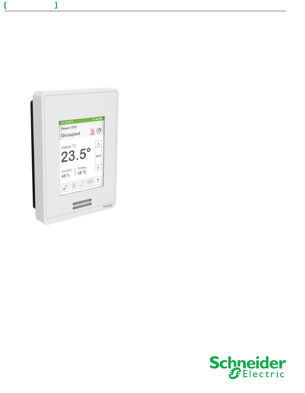
SER8300 Series
Terminal Equipment Controller with Optional PIR sensor
Installation Guide
Commercial and Hotel/Lodging HVAC Fan Coil Applications
CONTENTS
Installation 2
Location 2
Installation 2
Terminal, Identification and Function 3
Communication wiring to SC3xxxX Relay Pack 3
BACnet® Communication Wiring (if applicable) 3
Network wiring topology 3
How to Enter Setup Screen 4
Setup Screen Display 4
Specifications 5
Drawing and Dimensions 6
SER8300 Series 2
Installation Guide
Schneider Electric- Small Building Systems Tel. Americas: North Andover, MA 1-800-225-0962 Tel. Europe: Malmö, Sweden +46 40 38 68 50 Tel. Asia Pacific: Hong Kong +852 2565 0621
028-0418-01 www.schneider-electric.com/buildings October 2013 ct
© 2013 Schneider Electric. All rights reserved.
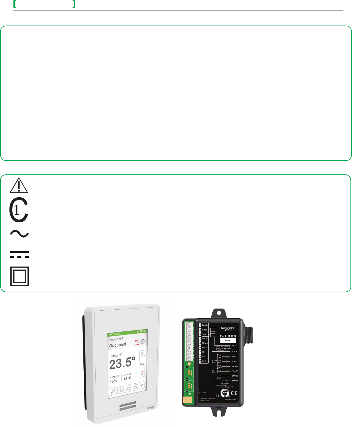
SER8000 Controller SC3000 Relay Pack
DISCLAIMER
• The SER8000 series controller is only to be used in conjunction with the SC3000 line voltage switching relay pack. Together they are used
as operating controls for high voltage fan coil units.
• If replacing an existing Line Voltage FCU Controller, label the wires before removal of the Controller.
• Electronic controls are static sensitive devices. Discharge yourself correctly before manipulating and installing the Terminal Equipment
Controller. A short circuit or wrong wiring may permanently damage the Terminal Equipment Controller or the equipment.
• All SER8300 series controls are designed for use as operating controls only and are not safety devices. These instruments have
undergone rigorous tests and verication prior to shipping to ensure proper and reliable operation in the eld. Whenever a control failure
could lead to personal injury and/or loss of property, it becomes the responsibility of the user/installer/electrical system designer to
incorporate safety devices such as relays, ow switches, thermal protections, and/or an alarm system to protect the entire system against
any catastrophic failures. Tampering with the devices or unintended application of the devices results in a void of warranty.
• If the equipment is used in a manner not specied by the manufacturer, the protection provided by the equipment may be impaired.
• These devices are not serviceable and must be returned to the supplier for any repair.
•A switch or circuit breaker must be installed. It must be suitably located, easily reached, and marked as the disconnecting device.
•Never apply more than 24VDC to get applied to the Controller
•This device complies with Industry Canada licence-exempt RSS standard(s). Operation is subject to the following two conditions: (1) this
device may not cause interference, and (2) this device must accept any interference, including interference that may cause undesired
operation of the device.
IMPORTANT SYMBOLS
Products marked with this symbol state that the manuals must be consulted in all cases to any hazards.
This product has been tested to the requirements of CAN/CAS-C22.2 No. 61010-1, second edition, including Amendment 1, or a
later version of the same standard incorporating the same level of testing requirements.
Alternating Current
Direct Current
Equipment protected throughout by DOUBLE INSULATION or REINFORCED INSULATION
SER8300 Series 3
Installation Guide
Schneider Electric- Small Building Systems Tel. Americas: North Andover, MA 1-800-225-0962 Tel. Europe: Malmö, Sweden +46 40 38 68 50 Tel. Asia Pacific: Hong Kong +852 2565 0621
028-0418-01 www.schneider-electric.com/buildings October 2013 ct
© 2013 Schneider Electric. All rights reserved.
• If replacing an existing Line Voltage FCU Controller, label wires
before removal of Controller.
• Electronic controls are static sensitive devices. Discharge
yourself correctly before manipulating and installing
Controller.
• A short circuit or wrong wiring may permanently damage
Controller or equipment.
• All SER8300 series controls are designed for use as operating
controls only and are not safety devices. Tampering with the
devices or unintended application of the devices will result in
a void of warranty.
• This transmitter must be installed to provide a separation
distance of at least 8in (20cm) from all persons and must
not be collocated or operating in conjunction with any other
antenna or transmitter.
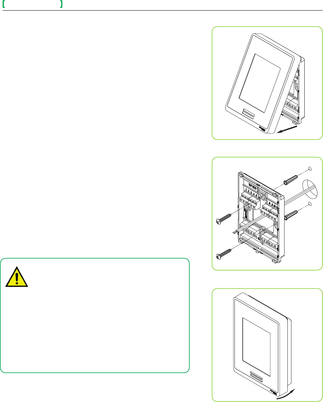
Figure-1 Open the cover
Figure-2 Install the base
Figure-3 Reinstall cover
INSTALLATION
Preparation
•
Open unit by pulling on bottom side of Terminal Equipment Controller (Fig. 1).
• Read FCC ID and IC label installed in cover before installing any wireless
product.
• Ensure correct side of base faces up.
Location
1. Do not install on outside wall.
2. Do not install in areas with direct heat source.
3. Do no install near any air discharge grill.
4. Do not install in areas exposed to direct sunlight.
5. Ensure Controller has sufcient air circulation.
6. Ensure wall surface is at and clean.
Installation
1. Pull cables 15 cm ( 6” ) out from wall.
2. Align base and mark location of two mounting holes on wall.
3. Install anchors in wall.
4. Insert cable in central hole of base.
5. Insert screws in mounting holes on each side of base.
6. Strip each wire 1/4” ( 0.6 cm) from end.
7. Insert each wire according to wiring chart (next page).
8. Gently push excess wiring back into hole.
9. Gently align cover to top of base and snap in place from bottom.
10. Install security screw.
SER8300 Series 4
Installation Guide
Schneider Electric- Small Building Systems Tel. Americas: North Andover, MA 1-800-225-0962 Tel. Europe: Malmö, Sweden +46 40 38 68 50 Tel. Asia Pacific: Hong Kong +852 2565 0621
028-0418-01 www.schneider-electric.com/buildings October 2013 ct
© 2013 Schneider Electric. All rights reserved.
Terminal Identification All SER83xxA
Terminal Equipment Controller
Terminal 4 Tx – Rx Communication
Terminal 5 Power Hot 7.0 VDC
Terminal 6 Power Common
Terminal 13 BACnet +
Terminal 14 BACnet -
Terminal 16 BI 1 ( Congurable )
Terminal 17 BI 2 ( Congurable )
Terminal 18 Scom
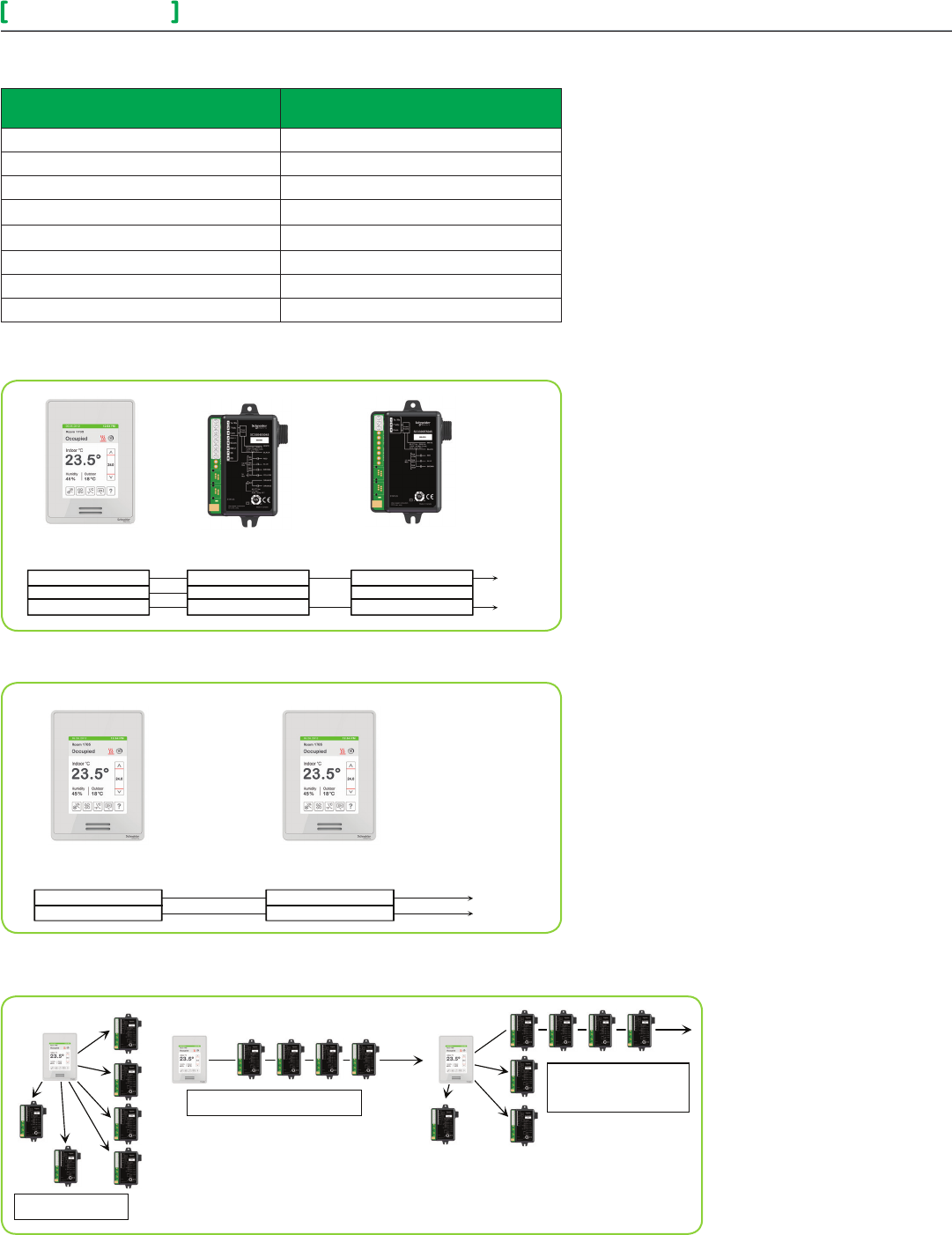
COMMUNICATION WIRING TO SC3XXXX RELAY PACK
TERMINAL, IDENTIFICATION AND FUNCTION
4 - Tx / Rx
5 - 7 Vdc Power Hot
6 - Power Common
SC3504E
SER83xxA
Terminal Controller
1 - Tx / Rx
2 - 7 Vdc Power Hot
3 - Power Common
1 - Tx / Rx
2 - 7 Vdc Power Hot
3 - Power Common
Relay Pack
SC3300E
Relay Pack
To oth
er
SC3xx
xX
Relay
Pack
Only ONE SC3xxxX Relay Pack with remote
monitoring inputs can be used under a single
SER83xxA Controller. All other slave units must be
SC3xxxX Relay Pack(s) without remote inputs.
A maximum of 10 SC3xxxX Relay Packs can be
used for a single SER83xxA Terminal Equipment
Controller.
From SER83xxA to First SC3xxxX Relay
Pack
• Uses existing or new eld wires.
• A minimum of 3 wires are required 14-22 Ga,
Solid, or Stranded. Shield not necessary.
From First SC3xxxX to all Other Slave
SC3xxxX Relay Pack(s)
• Uses existing or new eld wires.
• A minimum of 2 wires are required 14-22 Ga,
Solid, or Stranded.
• Shield not necessary.
• Connect only wires #1 Power Common and
#2 Tx/Rx Communication.
Daisy Chained Topology
Star Topology
Mixed Daisy Chained
&
Star Topology
Network Wiring Topology
13-COM +
14-COM -
SER83xxA
Terminal Controller
13-COM +
14-COM -
SER83xxA
Terminal Controller
To others
To others
BACnet® Communication Wiring (if applicable)
NOTE: See SER8300 BACnet® integration manual for more details
SER8300 Series 5
Installation Guide
Schneider Electric- Small Building Systems Tel. Americas: North Andover, MA 1-800-225-0962 Tel. Europe: Malmö, Sweden +46 40 38 68 50 Tel. Asia Pacific: Hong Kong +852 2565 0621
028-0418-01 www.schneider-electric.com/buildings October 2013 ct
© 2013 Schneider Electric. All rights reserved.
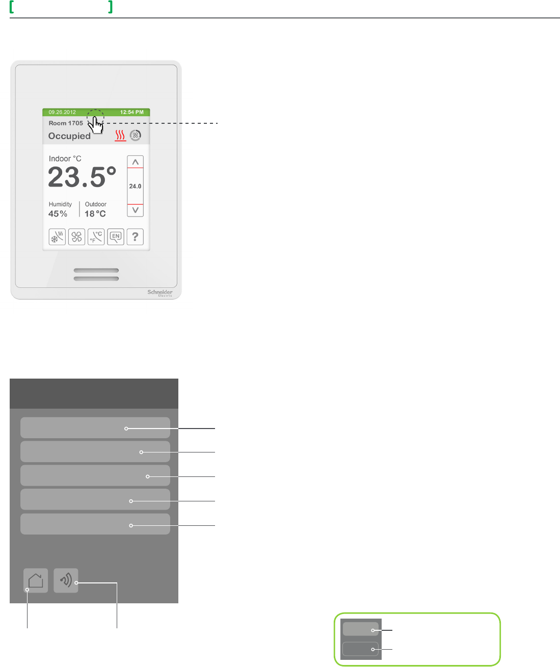
ENTER SET-UP SCREEN
Touch and hold this point
for 3 seconds to enter set-up mode
SET-UP SCREEN DISPLAY
Return to
home screen
General Note:
Setup
Network
Configuration
Setpoints - Display
Service view
Test outputs
Adjustable parameter
Non-adjustable parameter
Note: If a conguration/installer
password is activated to prevent
unauthorised access to the
conguration menu parameters, a
password entry prompt shows to
prevent access to device conguration
components.
Discover Mode The Controller
becomes discoverable on the wireless
ZigBee® network for 1 minute (this
button is hidden if ZigBee® settings are
not congured)
Enter BACnet® & ZigBee® network settings
Enter parameter conguration menu
Enter setpoint & display settings
Enter output testing mode
Enter status and service view
Note: The "Network" button does not show if no
BACnet® or ZigBee® card is installed.
SER8300 Series 6
Installation Guide
Schneider Electric- Small Building Systems Tel. Americas: North Andover, MA 1-800-225-0962 Tel. Europe: Malmö, Sweden +46 40 38 68 50 Tel. Asia Pacific: Hong Kong +852 2565 0621
028-0418-01 www.schneider-electric.com/buildings October 2013 ct
© 2013 Schneider Electric. All rights reserved.
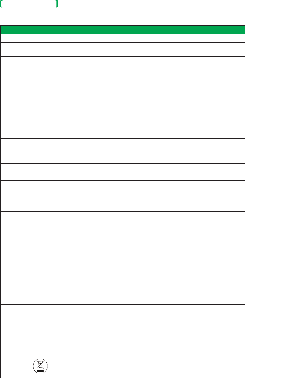
Specifications
Controller power requirements 7.0 VDC +/- 10% 2.4 watts minimum
Operating conditions 0 °C to 50 °C ( 32 °F to 122 °F )
0% to 95% R.H. non-condensing
Storage conditions -30 °C to 50 °C ( -22 °F to 122 °F )
0% to 95% R.H. non-condensing
Temperature sensor Local 10 K NTC type 2 thermistor
Temperature sensor resolution ± 0.1 °C ( ± 0.2 °F )
Temperature control accuracy
± 0.5 ° C ( ± 0.9 °F ) @ 21 °C ( 70 °F ) typical calibrated
Humidity sensor and calibration Single point calibrated bulk polymer type sensor
Humidity sensor precision
Reading range from 10-90 % R.H. non-condensing 10
to 20% precision is 10%
20% to 80% precision is 5%
80% to 90% precision is 10%
Humidity sensor stability Less than 1.0 % yearly (typical drift)
Dehumidication setpoint range 30% to 95% R.H.
Occ, Stand-By and Unocc cooling setpoint range 12.0 to 37.5 °C ( 54 to 100 °F )
Occ, Stand-By and Unocc heating setpoint range 4.5 °C to 32 °C ( 40 °F to 90 °F )
Room and outdoor air temperature display range -40 °C to 50 °C ( -40 °F to 122 °F )
Proportional band for room temperature control Cooling & Heating: Default: 1.8°C ( 3.2°F )
Binary inputs Dry contact across terminal BI1,
BI2 & UI3 to Scom
Wire gauge 14 gauge maximum, 22 gauge recommended
Approximate shipping weight 0.34 kg ( 0.75 lb )
Safety Standards (all models)
LVD Directive 2006/95/EC
UL 61010-1 (2nd edition)
CSA 61010-1(3rd edition)
IEC 61010-1 (3rd edition)
EMC Standards (all models)
EMC Directive 2004/108/EC
IEC 61326-1:2005
FCC 15 Subpart B
ICES-003
Radio Standards (wireless models)
R&TTE Directive 1999/5/EC
IEC 61326-1:2005
EN 301 489-1 V1.9.2
EN 301 328 V1.8.1
FCC 15 Subpart C
RSS 210
THIS DEVICE COMPLIES WITH PART 15 OF THE FCC RULES. OPERATION IS SUBJECT TO THE FOLLOWING
TWO CONDITIONS: (1) THIS DEVICE MAY NOT CAUSE HARMFUL INTERFERENCE, AND (2) THIS DEVICE
MUST ACCEPT ANY INTERFERENCE RECEIVED, INCLUDING INTERFERENCE THAT MAY CAUSE UNDESIRED
OPERATION.
THE GRANTEE IS NOT RESPONSIBLE FOR ANY CHANGES OR MODIFICATIONS NOT EXPRESSLY
APPROVED BY THE PARTY RESPONSIBLE FOR COMPLIANCE. SUCH MODIFICATIONS COULD VOID
THE USER’S AUTHORITY TO OPERATE THE EQUIPMENT.
Check with your local government for instruction on disposal of this product.
SER8300 Series 7
Installation Guide
Schneider Electric- Small Building Systems Tel. Americas: North Andover, MA 1-800-225-0962 Tel. Europe: Malmö, Sweden +46 40 38 68 50 Tel. Asia Pacific: Hong Kong +852 2565 0621
028-0418-01 www.schneider-electric.com/buildings October 2013 ct
© 2013 Schneider Electric. All rights reserved.
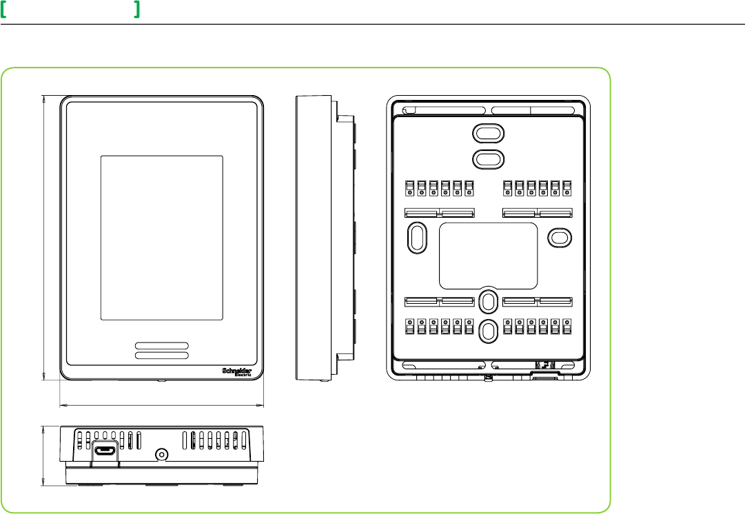
DIMENSIONAL DRAWING
86 mm (3.378”)
120 mm (4.722”)
25 mm
(0.990”)