Viconics Electronics VTP WIRELESS THERMOSTAT DATA TERMINAL User Manual
Viconics Electronics Inc. WIRELESS THERMOSTAT DATA TERMINAL
User Manual

1 | VT7682S Series-Installation Guide
CONTENTS
Installation 2
Location 2
Installation 2
Features overview 3
Model Number 4
Terminal, Identification and Function 4
Wiring 4
Screw terminal arrangement 5
Configuring and Status Display Instructions 7
Status display 7
User Interface 8
User configuring instructions menu 8
Local keypad interface 8
Occupied setpoints adjustments 9
Installer Configuration Parameter Menu 14
Troubleshooting guide 17
All models 17
Specifications 18
Drawing & Dimensions 19
VT7682S5000W
Wireless Central Manager
Installation Guide
For Commercial HVAC Applications
December 4t h 2012 / 028-0366-R1
2 | VT7682S Series-Installation Guide
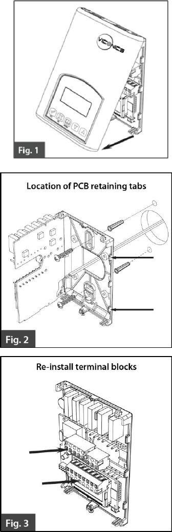
INSTALLATION
Remove the security screw on the bottom of
Terminal Equipment Controller cover.
Open unit by pulling on the bottom
side of Terminal Equipment
Controller (fig. 1).
Remove wiring terminals from sticker.
Please read the FCC ID and IC label
installed in the cover upon removal
of cover for the wireless products.
Location
1. Should not be installed on an outside
wall.
2. Must be installed away from any
direct heat source.
3. Should not be installed near an
air discharge grill.
4. Should not be affected by direct
sun radiation.
5. Nothing should restrict vertical
air circulation to the Terminal
Equipment Controller.
Installation
1. Swing open the Terminal
Equipment Controller PCB to
the left by pressing the PCB
locking tabs (fig. 2).
2. Pull out cables 6” out from the
wall.
3. Wall surface must be flat and
clean.
4. Insert cable in the central hole
of the base.
5. Align the base and mark the
location of the two mounting
holes on the wall. Install base in
proper orientation. Arrow on
base should be facing up.
6. Install anchors in the wall.
7. Insert screws in mounting holes
on each side of the base (fig. 2).
8. Gently swing back the circuit
board on the base and push on
it until the tabs lock it.
9. Strip each wire 1/4 inch from
end.

3 | VT7682S Series-Installation Guide
10. Insert each wire according to wiring diagram.
11. Gently push excess wiring back into hole (fig. 3).
12. Re-Install wiring terminals in their correct locations (fig. 3).
13. Re-install the cover (top side first) and gently push extra wire length back into
the hole in the wall.
14. Install security screw.
Features overview
7 day schedule (2 or 4 events).
Remote outdoor sensing capability for added flexibility.
System efficiency feedback.
Lockable keypads for tamper proofing. No need for Terminal Equipment Controller guards.
Local occupied setpoints.
Sends occupancy status of building to all wireless controllers on same channel and Pan ID.
Administer 60 controller units with one central master.
Displays which zones are in alarm mode.
Allows for setting of central occupied heating and cooling setpoints
Provides alarm monitoring of all zones
.
When replacing an existing Terminal Equipment Controller, label the
wires before removal of the Terminal Equipment Controller.
Electronic controls are static sensitive devices. Discharge yourself
properly before manipulating and installing the Terminal Equipment
Controller.
A short circuit or wrong wiring may permanently damage the Terminal
Equipment Controller or the equipment.
All VT7000 series Terminal Equipment Controllers are designed for use
as operating controls only and are not safety devices. These instruments
have undergone rigorous tests and verification prior to shipping to ensure
proper and reliable operation in the field. Whenever a control failure
could lead to personal injury and or loss of property, it becomes the
responsibility of the user / installer / electrical system designer to
incorporate safety devices (such as relays, flow switch, thermal
protections, etc…) and or an alarm system to protect the entire system
against such catastrophic failures. Tampering with the devices or
unintended application of the devices will result in a void of warranty.
4 | VT7682S Series-Installation Guide
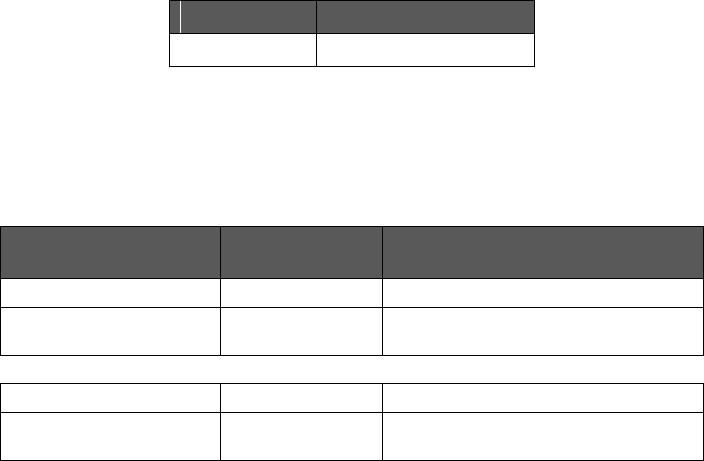
MODEL NUMBER
Part number
Description
VT7682S5000W
Wireless Central Manager
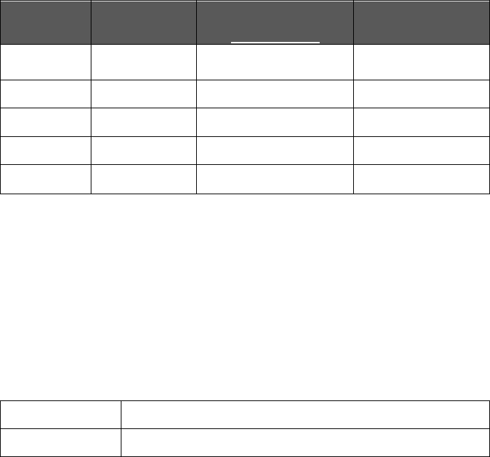
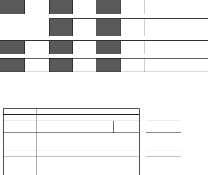
TERMINAL, IDENTIFICATION AND FUNCTION
Wiring
Terminal Use
Terminal
Identification
Description
4 – RC 24Vac hot
24 V ~ Hot
Power supply of controller (hot side)
5 – C 24Vac com
0 V ~ Com
Power supply of controller (com
side)
14 – Scom
Scom
Reference input for OS
15 – OS
OS
Outside air temperature sensor
input
5 | VT7682S Series-Installation Guide
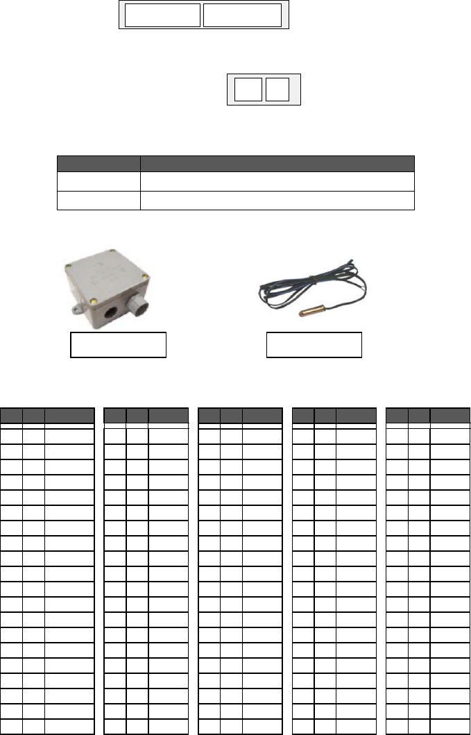
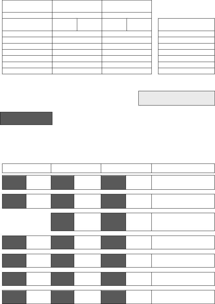
Screw terminal arrangement
Outdoor sensor accessories
MODEL NO.
DESCRIPTION
S2020E1000
Outdoor temperature sensor (NEMA 4 Enclosure)
S1010E1000
Outdoor temperature sensor
Outdoor temperature sensors use 10K NTC thermistor.
Temperature vs. resistance chart for 10 Kohm NTC thermistor
ºC
ºF
Kohm
ºC
ºF
Kohm
ºC
ºF
Kohm
ºC
ºF
Kohm
ºC
ºF
Kohm
-40
-40
324.3197
-20
-4
94.5149
0
32
32.1910
20
68
12.4601
40
104
5.3467
-39
-38
303.6427
-19
-2
89.2521
1
34
30.6120
21
70
11.9177
41
106
5.1373
-38
-36
284.4189
-18
0
84.3147
2
36
29.1197
22
72
11.4018
42
108
4.9373
-37
-35
266.5373
-17
1
79.6808
3
37
27.7088
23
73
10.9112
43
109
4.7460
-36
-33
249.8958
-16
3
75.3299
4
39
26.3744
24
75
10.4443
44
111
4.5631
-35
-31
234.4009
-15
5
71.2430
5
41
25.1119
25
77
10.0000
45
113
4.3881
-34
-29
219.9666
-14
7
67.4028
6
43
23.9172
26
79
9.5754
46
115
4.2208
-33
-27
206.5140
-13
9
63.7928
7
45
22.7861
27
81
9.1711
47
117
4.0607
-32
-26
193.9703
-12
10
60.3980
8
46
21.7151
28
82
8.7860
48
118
3.9074
-31
-24
182.2686
-11
12
57.2044
9
48
20.7004
29
84
8.4190
49
120
3.7607
-30
-22
171.3474
-10
14
54.1988
10
50
19.7390
30
86
8.0694
50
122
3.6202
-29
-20
161.1499
-9
16
51.3692
11
52
18.8277
31
88
7.7360
51
124
3.4857
-28
-18
151.6239
-8
18
48.7042
12
54
17.9636
32
90
7.4182
52
126
3.3568
-27
-17
142.7211
-7
19
46.1933
13
55
17.1440
33
91
7.1150
53
127
3.2333
-26
-15
134.3971
-6
21
43.8268
14
57
16.3665
34
93
6.8259
54
129
3.1150
-25
-13
126.6109
-5
23
41.5956
15
59
15.6286
35
95
6.5499
55
131
3.0016
-24
-11
119.3244
-4
25
39.4921
16
61
14.9280
36
97
6.2866
56
133
2.8928
-23
-9
112.5028
-3
27
37.5056
17
63
14.2629
37
99
6.0351
57
135
2.7886
-22
-8
106.1135
-2
28
35.6316
18
64
13.6310
38
100
5.7950
58
136
2.6886
-21
-6
100.1268
-1
30
33.8622
19
66
13.0307
39
102
5.5657
59
138
2.5926
S1010E1000
S2020E1000
Scom
OS
24 V ~ Hot
0 V ~ Com
Left top connector
Bottom connector
6 | VT7682S Series-Installation Guide
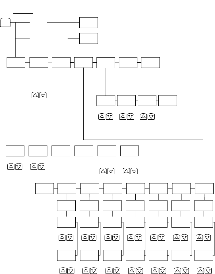
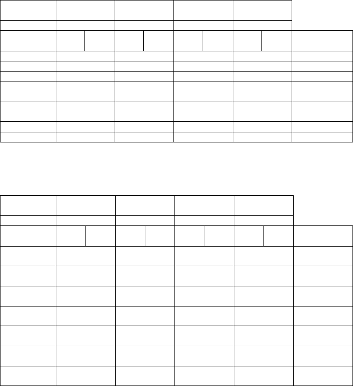
User menu flow chart:
NOTE: Prompts may not all be present depending on model selected
Time
Occupied
day? Y/N
Occupied
12:00 pm
Time
Unoccup
12:00 pm
Time
Occupied
day? Y/N
Occupied
12:00 pm
Time
Unoccup
12:00 pm
Time
Occupied
day? Y/N
Occupied
12:00 pm
Time
Unoccup
12:00 pm
Time
Occupied
day? Y/N
Occupied
12:00 pm
Time
Unoccup
12:00 pm
Time
Occupied
day? Y/N
Occupied
12:00 pm
Time
Unoccup
12:00 pm
Time
Exit?
Y/N
off
heat
cool
auto
Override
schd Y/N
Cancel
ovrd Y/N
If status is:
Unoccupied
If status is:
Temporary Occupied Time,
Schedule
set? Y/N
Sys mode
set? Y/N
Clock
set? Y/N
Temperat
set? Y/N
Exit
menu Y/N
°F/°C
set? Y/N
Heating
set? Y/N
Cooling
set? Y/N
°C
°F
Exit?
Y/N
Temperature
Temperature
MENU
12/24hrs
set? Y/N
12 / 24
Time
set? Y/N
Time
Day
set? Y/N
Day
Sunday
set? Y/N
Saturday
set? Y/N
Friday
set? Y/N
Thursday
set? Y/N
Wednesda
set? Y/N
Tuesday
set? Y/N
Monday
set? Y/N
Exit?
Y/N
Occupied
day? Y/N
Occupied
12:00 pm
Time
Unoccup
12:00 pm
Time
Occupied
day? Y/N
Occupied
12:00 pm
Time
Unoccup
12:00 pm
7 | VT7682S Series-Installation Guide
CONFIGURING AND STATUS DISPLAY INSTRUCTIONS
Status display
The Terminal Equipment Controller features a two-line, eight-character display. There is a
low level backlight that is always active and can only be seen at night.
When left unattended, the Terminal Equipment Controller has an auto scrolling display
that shows the current status of the system.
Each item is scrolled sequentially with the back lighting in low level mode. Pressing any
key will cause the back light to come on to high level.
Manual scrolling of each menu item is achieved by pressing the Yes (scroll) key
repetitively. The last item viewed will be shown on the display for 30 seconds before
returning to automatic scrolling. Temperature is automatically updated when scrolling is
held.
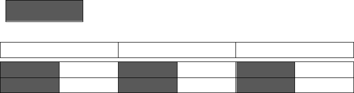
Sequence of auto-scroll status display:
CLOCK
STATUS
SCHEDULE
STATUS
OUTDOOR
TEMPERATURE
IF CONNECTED
ALARMS
Monday
12:00 AM
Occupied
Outdoor
x.x °C or°F
SetClock
Unoccupied
Zone X**
Override
Zone Y**
Zone Z**
Dup Zig(Duplicate
Zigbee Address)***
** X, Y, Z is the MAC address of the zone that has the alarm.
Outdoor air temperature
Outdoor air temperature display is only enabled when outdoor air temperature sensor is
connected.
A maximum range status display of 50 °C (122 °F) indicates a shorted sensor.
Associated functions, such as mode lockouts and economizer function are
automatically disabled.
A minimum range status -40 °C (-40 °F) is not displayed and indicates an opened
sensor or a sensor not connected. Associated functions, such as mode lockouts and
economizer function are automatically disabled.
Alarms
SetClock
Indicates that the clock needs to be reset. There has been a power
failure which has lasted longer than 6 hours
Dup Zig (Duplicate
Zigbee Address)***
Two or more devices hold identical Zigbee addresses
*** Restart the network by changing the PAN ID.
8 | VT7682S Series-Installation Guide
If alarms are detected, they will automatically be displayed at the end of the status
display scroll.
During an alarm message display, the back lit screen will light up at the same time as
the message and shut off during the rest of the status display.
Two alarms maximum can appear at any given time.
The range of zones that can be in alarm is 1 to 253.
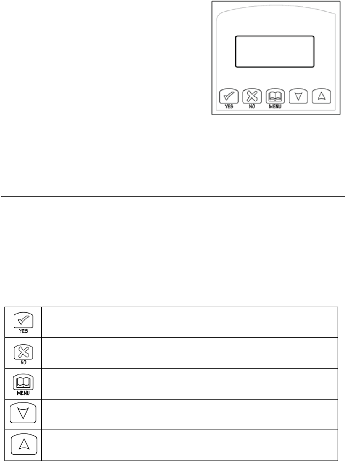
USER INTERFACE
User configuring instructions menu
The VT7682S series Terminal Equipment Controller
feature an intuitive, menu-driven, back-lit LCD
display that walks users through the configuring
steps, making the configuring process extremely
simple. This menu is typically accessed by the user
to set the parameters such as temperature and time
events, system mode etc...
It is possible to bring up the user menu at any time
by depressing the MENU key. The status display automatically resumes after exiting the
user-configuring menu.
If the user pauses at any given time during configuring, Auto Help text is displayed to help
and guide the user through the usage and configuring of the Terminal Equipment
Controller.
Ex.:
Press yes key to change cooling temperature setpoint
Use the up or down arrow to adjust cooling setpoint
Local keypad interface
Each of the sections in the menu is accessed and configured using 5 keys on the
Terminal Equipment Controller cover.
The priority for the alarms is as follows:
The YES key is used to confirm a selection, to move onto the next menu item
and to manually scroll through the displayed information.
The NO key is used when you do not desire a parameter change, and to
advance to the next menu item. Can also be used to toggle between heating
and cooling setpoints.
The MENU key is used to access the Main User Menu or exit the menu.
The down arrow key is used to decrease temperature setpoint and to adjust
the desired values when configuring the Terminal Equipment Controller.
The up arrow key is used to increase temperature setpoint and to adjust the
desired values when configuring the Terminal Equipment Controller.
9 | VT7682S Series-Installation Guide
When left unattended for 45 seconds, the display will resume automatic status display
scrolling.
To turn on the back light, press any key on the front panel. The back lit display will turn off
when the Terminal Equipment Controller is left unattended for 45 seconds
Sequence of user menu:
OVERRIDE
RESUME
TEMPERATURE
SETPOINTS
SYSTEM
MODE
SETTING
SCHEDULES
SETTING
CLOCK
SETTING
Override
schd Y/N
Temperat
Set Y/N
Sys mode
set Y/N
Schedule
set Y/N
Clock
set Y/N
Appears only in
unoccupied mode
Cancel
ovrd Y/N
Appears only in
override mode
Occupied setpoints adjustments
There is a default profile set in the Terminal Equipment Controller from the factory.
DEFAULT TEMPERATURE SETPOINTS:
DEFAULT MODES:
Occupied cooling setpoint = 24 °C (75 °F)
System mode = Auto
Occupied heating setpoint = 22 °C (72 °F)
Monday through Sunday
Fahrenheit scale
Occupied time is : 12:00 AM
Unoccupied time is: 11:59 PM
There will be a 1 minute unoccupied period every night at 11:59 PM with this default configuration.
A) Override an unoccupied period
Override
schd Y/N
This menu will appear only when the Terminal Equipment Controller is in unoccupied
mode. Answering yes to this prompt will cause the Terminal Equipment Controller to go
into occupied mode for an amount of time equal to the parameter “TOccTime” (1 to 12
hours).
B) Resume regular scheduling
Cancel
ovrd Y/N
This menu does not appear in regular operation. It will appear only when the Terminal
Equipment Controller is in Unoccupied override mode.
Answering “Yes” to this question will cause the Terminal Equipment Controller to resume
the regular setpoints & scheduling.
10 | VT7682S Series-Installation Guide
C) Temperature setpoints
Temperat
set Y/N
This menu permits the adjustment of occupied temperature setpoints as well as the
desired temperature units (°F or °C). Setpoints are written to RAM and EEPROM.
Cooling setpoint
Occupied mode
Heating setpoint
Occupied mode
°F or °C
display setting
Cooling
set? Y/N
No next
Yes down
Heating
set? Y/N
No next
Yes down
°F or °C
set? Y/N
No next
Yes down
Use ▲▼ keys to set value, Yes key to confirm
Cooling
70.0 °F
Use ▲▼
To set value
Heating
68.00 °F
Use ▲▼
To set value
Units
°F
Use ▲▼
To set value
D) System mode setting
Sys mode
set Y/N
This menu is accessed to set system mode operation
Use ▲▼ to set value, Yes key to confirm
Sys mode
auto
Automatic mode
Automatic changeover mode between heating and cooling operation
Sys mode
cooling
Cooling mode
Cooling operation mode only
Sys mode
heating
Heating mode
Heating operation mode only
Sys mode
off
Off mode Normal cooling or heating operation disabled
If enabled in installer parameters, only the automatic heating frost protection
at 50 °F ( 10 °C ) is enabled
E) Schedule set (2 events)
Scheduling can have 2 or 4 events per day. This is set in the configuration menu as per
parameter (2/4event)
Schedule
set Y/N
This section of the menu permits the user to set the whether 2 or 4 events is needed.
Each day can be tailored to specific schedules if needed.
2 events can be scheduled per day.
Occupied & unoccupied periods can be set for each day.
MONDAY TIMER
SCHEDULE SET
TUESDAY
TIMER
SCHEDULE SET
WEDNESDAY
TIMER
SCHEDULE SET
OTHER DAYS ARE
IDENTICAL
Monday
set? Y/N
No next
Yes down
Tuesday
set? Y/N
No next
Yes down
Wednesda
set? Y/N
No next
Yes down
Selects the day to be scheduled or
modified
Yes key to access day scheduling, No key to jump to next day
11 | VT7682S Series-Installation Guide
Occupied
Day? Y/N
No next
Yes down
Occupied
Day? Y/N
No next
Yes down
Occupied
Day? Y/N
No next
Yes down
Yes = Daily schedules will be
accessed
No = Unoccupied mode all day
Yes key to access day scheduling, No key to jump to next day
Copy Y/N
Previous
Yes next
No down
Copy Y/N
Previous
Yes next
No down
Yes = Will copy previous day
schedule
No = Daily schedules will be
accessed
Yes key to copy previous day, No key to set new time value for each day
Occupied
00:00 AM
Use ▲▼
To set
value
Occupied
00:00 AM
Use ▲▼
To set
value
Occupied
00:00 AM
Use ▲▼
To set
value
Sets Event # 1 Occupied time
Will activate occupied setpoints
Use ▲▼ to set value, Yes key to confirm
Unoccup
00:00 AM
Use ▲▼
To set
value
Unoccup
00:00 AM
Use ▲▼
To set
value
Unoccup
00:00 AM
Use ▲▼
To set
value
Sets Event # 2 Unoccupied time
Will activate unoccupied setpoints
Use ▲▼ to set value, Yes key to confirm
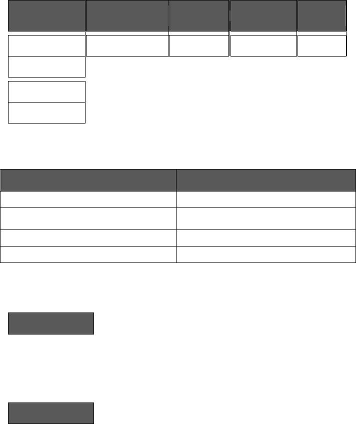
Typical examples of a 2 event office schedule:
Ex. #1 Office building closed all weekend
Event
Period #1 - Event #1
Period #1 - Event #2
Occupied
Unoccupied
Setpoint
Cool
Heat
Cool
Heat
Daily
72 °F
70 °F
80 °F
62 °F
Occupancy
Monday
7.00 AM
6.00 PM
Day time only
Tuesday
7.00 AM
6.00 PM
Day time only
Wednesday
7.00 AM
6.00 PM
Day time only
Thursday
7.00 AM
6.00 PM
Day time only
Friday
7.00 AM
6.00 PM
Day time only
Saturday
12.00 PM *
12.00 PM *
Unoccupied
Sunday
12.00 PM *
12.00 PM *
Unoccupied
* Scheduling consecutive events to the same time will cause the Terminal Equipment
Controller to choose the last event as the time at which it will set its schedule. In the
above example, the Terminal Equipment Controller will control to the unoccupied set
point until 7:00 AM Monday.
12 | VT7682S Series-Installation Guide
Ex. #2 Commercial building which is occupied all weekend
Event
Period #1 - Event
#1
Period #1 - Event
#2
Occupied
Unoccupied
Setpoint
Cool
Heat
Cool
Heat
Daily
72 °F
70 °F
80 °F
62 °F
Occupancy
Monday
8.00 AM
5.00 PM
Day time only
Tuesday
8.00 AM
5.00 PM
Day time only
Wednesday
8.00 AM
5.00 PM
Day time only
Thursday
8.00 AM
5.00 PM
Day time only
Friday
8.00 AM
5.00 PM
Day time only
Saturday
12.00 AM **
11.59 PM **
Occupied
Sunday
12.00 AM **
11.59 PM **
Occupied
** To schedule a day as occupied for 24 hours, set that day occupied time to 12:00 AM
and Unoccupied time to 11:59 PM There will be a 1 minute unoccupied period every
night at 11:59 PM with this schedule configuration.
G) Schedule set (4 events)
Schedule
set Y/N
This section of the menu permits the user to set the whether 2 or 4 events is needed. Each
day can be tailored to specific schedules if needed.
4 events can be scheduled per day.
Occupied & Unoccupied periods can be set for each day.
Scheduling the 3rd. & 4th. Events to the same time will cancel the last period.
Monday timer
Schedule set
Tuesday timer
Schedule set
Wednesday timer
Schedule set
Other days are identical
Monday
set? Y/N
No next
Yes down
Tuesday
set? Y/N
No next
Yes down
Wednesda
set? Y/N
No next
Yes down
Selects the day to be scheduled or
modified
Yes key to access day scheduling, No key to jump to next day
Occupied
Day? Y/N
No next
Yes down
Occupied
Day? Y/N
No next
Yes down
Occupied
Day? Y/N
No next
Yes down
Yes = Daily schedules will be
accessed
No = Unoccupied mode all day
Yes key to access day scheduling, No key to jump to next day
Copy Y/N
Previous
Yes next
No down
Copy Y/N
Previous
Yes next
No down
Yes = Will copy previous day
schedule
No = Daily schedules will be
accessed
Yes key to copy previous day, No key to set new time value for each day
Occupied
00:00 AM
Use ▲▼
To set
value
Occupied
00:00 AM
Use ▲▼
To set
value
Occupied
00:00 AM
Use ▲▼
To set
value
Sets Event # 1 Occupied time
Will activate occupied setpoints
Use ▲▼ to set value, Yes key to confirm
Unoccup
00:00 AM
Use ▲▼
To set
value
Unoccup
00:00 AM
Use ▲▼
To set
value
Unoccup
00:00 AM
Use ▲▼
To set
value
Sets Event # 2 Unoccupied time
Will activate unoccupied
setpoints
Use ▲▼ to set value, Yes key to confirm
Occupie2
00:00 AM
Use ▲▼
To set
value
Occupie2
00:00 AM
Use ▲▼
To set
value
Occupie2
00:00 AM
Use ▲▼
To set
value
Sets Event # 3 Occupied time
Will activate occupied setpoints
Use ▲▼ to set value, Yes key to confirm
Unoccup2
00:00 AM
Use ▲▼
To set
value
Unoccup2
00:00 AM
Use ▲▼
To set
value
Unoccup2
00:00 AM
Use ▲▼
To set
value
Sets Event # 4 Unoccupied time
Will activate unoccupied
setpoints
Use ▲▼ to set value, Yes key to confirm
Note: 12:00 PM = Noon
12:00 AM = Midnight
13 | VT7682S Series-Installation Guide
Ex. #1 Four event retail establishment schedule
Event
Period 1 -
Event 1
Period 1 -
Event 2
Period 2 -
Event 3
Period 2 -
Event 4
Setpoint
Occupied
Unoccupied
Occupied
Unoccupied
Cool
Heat
Cool
Heat
Cool
Heat
Cool
Heat
Daily
72°F
70°F
80°F
62°F
72°F
70 °F
80°F
62 °F
Occupancy
Monday
7.00 AM
5.00 PM
12.00 PM *
12.00 PM *
Day time only
Tuesday
7.00 AM
5.00 PM
12.00 PM *
12.00 PM *
Day time only
Wednesday
7.00 AM
5.00 PM
12.00 PM *
12.00 PM *
Day time only
Thursday
7.00 AM
5.00 PM
7.00 PM
10.30 PM
Day/evening
time only
Friday
7.00 AM
5.00 PM
7.00 PM
10.30 PM
Day/evening
time only
Saturday
12.00 PM *
12.00 PM *
12.00 PM *
12.00 PM *
Unoccupied
Sunday
12.00 PM *
12.00 PM *
12.00 PM *
12.00 PM *
Unoccupied
* Scheduling events to the same time will cancel the last period and leave the Terminal
Equipment Controller in unoccupied mode
Ex. #2 Residential
Event
Period 1 -
Event 1
Period 1 -
Event 2
Period 2 -
Event 3
Period 2 -
Event 4
Setpoint
Occupied
Unoccupied
Occupied
Unoccupied
Cool
Heat
Cool
Heat
Cool
Heat
Cool
Heat
Daily
72°F
70°F
80°F
62°F
72°F
70°F
80°F
62°F
Occupancy
Monday
6:00 AM
8:00 AM
4:00 PM
10:00 PM
Day/evening
time only
Tuesday
6:00 AM
8:00 AM
4:00 PM
10:00 PM
Day/evening
time only
Wednesday
6:00 AM
8:00 AM
4:00 PM
10:00 PM
Day/evening
time only
Thursday
6:00 AM
8:00 AM
4:00 PM
10:00 PM
Day/evening
time only
Friday
6:00 AM
8:00 AM
4:00 PM
11:30 PM
Day/evening
time only
Saturday
8:00 AM *
8:00 AM *
8:00 AM *
11:59 PM *
Day time
only
Sunday
12:00 AM *
12:00 AM *
12:00 AM *
11:59 PM *
Occupied all
day
* Scheduling consecutive events to the same time will cause the Terminal Equipment
Controller to choose the last event as the time at which it will set its schedule. In the above
example for Saturday, the Terminal Equipment Controller will control to the occupied set
point from 8:00 AM until 11:59 PM. Since it is desired to be in occupied mode throughout
the night, then it is necessary to schedule the first event on Sunday at 12:00 AM. The
Terminal Equipment Controller will force a one minute unoccupied period for a one minute
period (between 11:59 PM and 12:00 AM on Saturday).
14 | VT7682S Series-Installation Guide
H) Clock/Day Settings
Clock
set Y/N
This section of the menu permits the user to set the time and day.
Time setting
Day setting
Time format setting
Time
set? Y/N
No next
Yes down
Day
set? Y/N
No next
Yes down
12/24hrs
set? Y/N
No = exit
Yes down
Time
0:00
Use ▲▼
To set value
Day
Monday
Use ▲▼
To set value
12/24hrs
12 hrs
Use ▲▼
To set value
INSTALLER CONFIGURATION PARAMETER MENU
Configuration can be done through the network or locally at the Terminal Equipment
Controller.
To enter configuration, press and hold the middle button “Menu” for 8 seconds
If a password lockout is active, “Password” is prompted. Enter password value using the
“up” and “down” arrows and press “Yes” to gain access to all configuration properties of
the Terminal Equipment Controller. A wrong password entered will prevent local access to
the configuration menu.
Once in the configuration menu, press the “No” button repetitively to scroll between all the
available parameters.
When the desired parameter is displayed, press “Yes” to adjust it to the desired value
using “up” and “down” arrows. Once set, press “Yes” to scroll to the next parameter.

15 | VT7682S Series-Installation Guide
CONFIGURATION
PARAMETERS
DEFAULT VALUE
SIGNIFICANCE AND ADJUSTMENTS
PswrdSet
Configuration parameters
menu access password
Default value = 0
No password prompted
This parameter sets a password access to prevent
unauthorized access to the configuration menu
parameters. A default value of “0” will not prompt a
password or lock the access to the configuration
menu.
Range is: 0 to 1000
Com Addr
Terminal Equipment
Terminal Equipment Controller
networking address
Default value = 254
This parameter is used to set the MAC address.
Range is: 0 to 254
PAN ID
Personal Area Network
Identification
Default value = 0
This parameter (Personal Area Network
Identification) is used to link specific Terminal
Equipment Controllers to a single specific Viconics
VT7682S Wireless Central Manager. A maximum of
120 Terminal Equipment Controller can be linked to a
single VT7682S Wireless Central Manager. Be sure
you set the SAME PAN ID value both at the Wireless
Central Manager and the Terminal Equipment
Controller(s).
The default value of 0 is NOT a valid PAN ID.
Range is: 0 to 500
Channel
Channel selection
Default value = 10
Range is: 10 to 25
This parameter (Channel) is used to link specific
thermostats to specific Terminal Equipment
Controllers to a single specific Viconics VT7682S
Wireless Central Manager. A maximum of 120
Terminal Equipment Controller can be linked to a
single VT7682S Wireless Central Manager. Be sure
you set the SAME PAN ID value both at the Wireless
Central Manager and the Terminal Equipment
Controller(s).
Viconics recommends using only the 2 last channels
( 24-@ 2470MHz and 25-@ 2475MHz )
The default value of 10 is NOT a valid channel. The
valid range of available channel is from 11 to 25
16 | VT7682S Series-Installation Guide
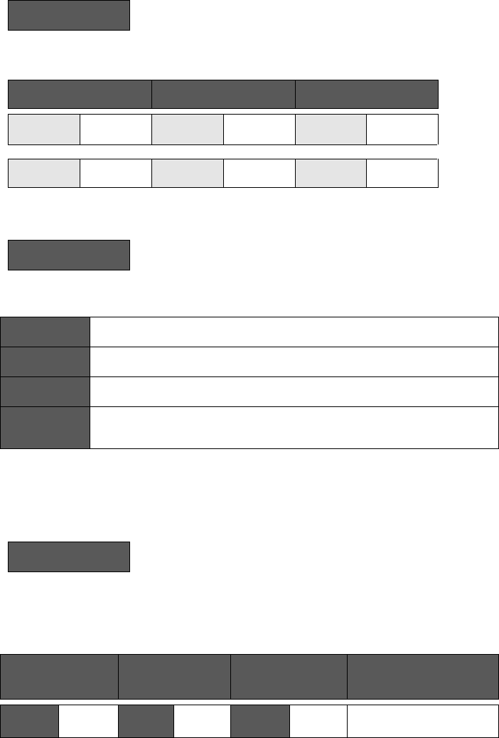
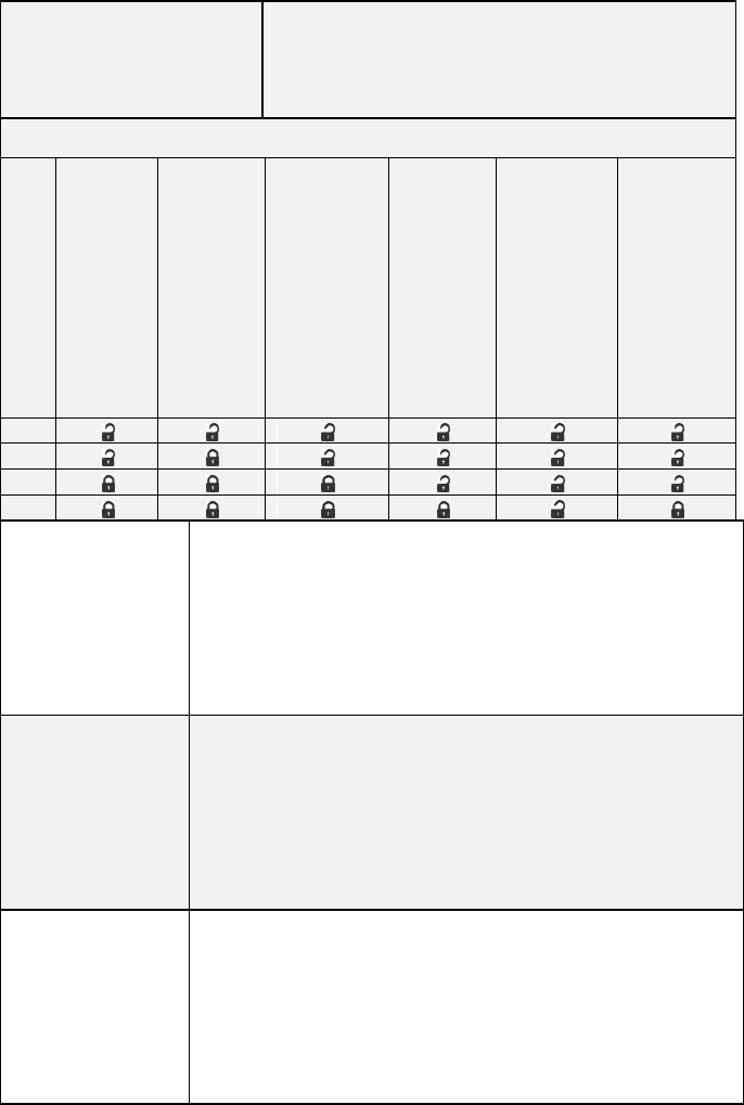
lockout Keypad lockout levels
Default value = 0 No lock
0 = No lock
1 = Low level
2 = Medium level
3 = High Level
USER KEY FUNCTIONS
LEVEL
Resume/
Override scheduling
Occupied Setpoints
System Mode Setting
Schedule Setting
Clock Setting
Permanent Hold
0
1
2
3
ToccTime
Temporary
occupancy time
Default value = 3
hours
Temporary occupancy time with occupied mode setpoints when
override function is enabled
When the Terminal Equipment Controller is in unoccupied mode,
function is enabled with either the menu or DI1 or DI2 configured
as remote override input.
0,1, 2, 3, 4, 5, 6, 7, 8, 9, 10, 11 & 12 hours
Cal OS
Outside air
temperature sensor
calibration
Default value = 0.0 °F
or °C
Offset that can be added/subtracted to actual displayed outside air
temperature
± 5.0 °F ( ± 2.5 °C )
2/4event
Number of events
configuration
Default value = 2
event
2 events, will set up scheduling for the following
Event 1 is for Occupied setpoints
Event 2 is for Unoccupied setpoints
4 events, will set up scheduling for the following
Event 1 is for Occupied setpoints
Event 2 is for Unoccupied setpoints
Event 3 is for Occupied setpoints
Event 4 is for Unoccupied setpoints

17 | VT7682S Series-Installation Guide
TROUBLESHOOTING GUIDE
All models
Symptom
Possible Cause
Corrective Action
No display on the
Terminal
Equipment
Controller
Absent or incorrect
supply voltage
1. Check power supply voltage between C
& RC to be from 19-30 VAC
2. Check for tripped fuse or circuit breaker
Overloaded power
transformer
Verify that the transformer used is
powerful enough (enough VA’s) to supply
all controlled devices including the
Terminal Equipment Controller
Keyboard menu
does not access
all functions
Keyboard locked
Change configuration parameter
LOCKOUT to value “0” to access all levels
of the menu
Digital display
shows missing
digits or erratic
segments
Defective display
Replace Terminal Equipment Controller

18 | VT7682S Series-Installation Guide
SPECIFICATIONS
Terminal Equipment Controller power
requirements:
Operating conditions:
Storage conditions:
Outdoor air Temperature sensor
Wire gauge:
Approximate shipping weight:
Agency Approvals all models:
Agency Approvals all models:
Agency Approvals Wireless models:
19-30 VAC 50 or 60 Hz; 2 VA Class 2
0 °C to 50 °C ( 32 °F to 122 °F )
0% to 95% R.H. non-condensing
-30 °C to 50 °C ( -22 °F to 122 °F )
0% to 95% R.H. non-condensing
-40 °C to 50 °C ( -40 °F to 122 °F )
18 gauge maximum, 22 gauge
0.75 lb ( 0.34 kg )
UL: UL 873 (US) and CSA C22.2 No.
24 (Canada), File E27734 with CCN
XAPX (US) and XAPX7 (Canada)
Industry Canada: ICES-003 (Canada)
FCC: Compliant to CFR 47, Part 15,
Subpart B, Class A (US)
CE : EMC Directive 89/336/EEC
(Europe Union)
C-Tick: AS/NZS CISPR 22 Compliant
(Australia / New Zealand) Supplier
Code Number N10696
FCC: Compliant to: Part 15, Subpart C
FCC Certification Requirements:
THIS DEVICE COMPLIES WITH PART 15 OF THE FCC RULES. OPERATION IS SUBJECT
TO THE FOLLOWING TWO CONDITIONS: (1) THIS DEVICE MAY NOT CAUSE HARMFUL
INTERFERENCE, AND (2) THIS DEVICE MUST ACCEPT ANY INTERFERENCE RECEIVED,
INCLUDING INTERFERENCE THAT MAY CAUSE UNDESIRED OPERATION
Please check with your local government for instruction on disposal of this product
19 | VT7682S Series-Installation Guide
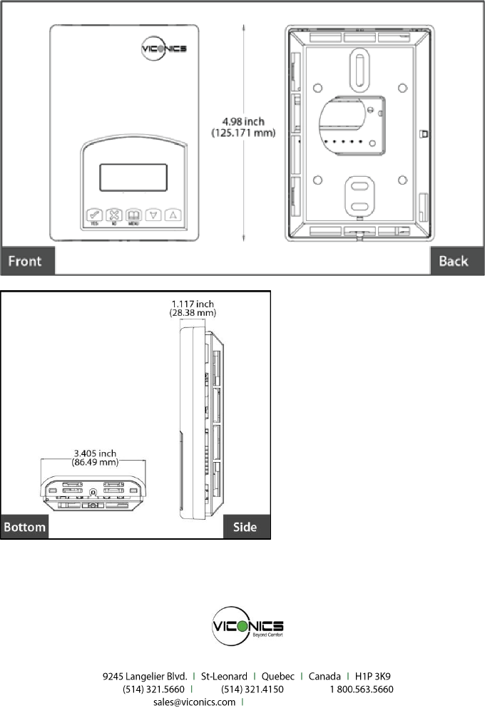
DRAWING & DIMENSIONS
Viconics Technologies Inc.
Tel.: Fax: Toll free:
www.viconics.com