Viconics Electronics VWA WIRELESS SWITCH ACCESSORY FOR THERMOSTAT APPLICATIONS User Manual 028 0321 R0 CS VWA5000W E02x
Viconics Electronics Inc. WIRELESS SWITCH ACCESSORY FOR THERMOSTAT APPLICATIONS 028 0321 R0 CS VWA5000W E02x
Users Manual
1
VWA5000 Series
Wireless Accessories
For Commercial and Lodging HVAC VTR7000 Series Fan Coil Controller
(Issue Date: May 10, 2011 – 028-0321_R0)
Product overview
The VWA5000W series of ZigBee wireless switches is used in conjunction
with the Wireless versions of the VTR73XX Series Fan Coil Terminal
Equipment Controllers.
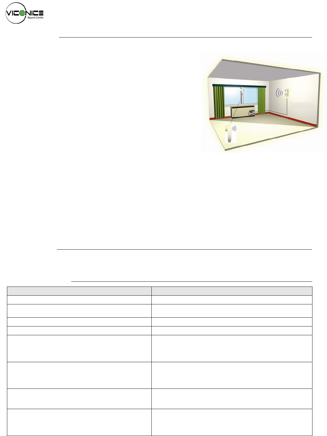
A typical hospitality application is where the VTR73xx wall terminal
equipment controller has an on-board PIR sensor and wireless switches are
used to monitor opening and closing of entry doors & windows.
Wireless door switches used with the local VTR73xx PIR cover provides
advanced local occupancy routine which provides advantageous energy
savings during occupied hours without sacrificing occupant comfort.
Wireless window switches are used to monitor outside windows being
opened or not. This allows for critical system shut-down of heating or cooling
by the FCU to prevent unwanted energy waste by tenants.
Typical applications of VTR73xx Series Fan Coil Terminal Equipment
Controllers with VWA5000W series of ZigBee wireless switches can be used
in stand-alone mode with or without integration to a central management
system for higher level functions such as central reservation occupancy
system.
A combination of up to 20 x VWA5000W door and / or window switches can be used simultaneously with a single VTR73xx Series
Fan Coil Terminal Equipment Controller.
The VWA5000W switches are factory delivered with 2 AAA batteries & are ready to be installed, configured & used right out of the
box. The expected battery life is around 10 years which is more or less equivalent to the shelf life of the battery due to the extremely
small current consumption of the switch themselves.
No tools are required for commissioning or servicing. A very simple interface with an on-board LED & a hidden switch provide all the
required functions for local interaction. Local information for battery life and connectivity ( heartbeat ) is provided also at the
VTR73xx Series Fan Coil Terminal Equipment Controller local display level or through the ZigBee wireless network with a Viconics
VWG-APP-1000 wireless communication card through Niagara AX™ software framework.
Each switch is also factory supplied with a magnet, a locking security tamper proof screw and self tapping mounting screws for
installation.
Models available
VWA5000W5000W: 1 x wireless window switch, complete with magnet, batteries and required mounting hardware
VWA5000D5000W 1 x wireless door switch, complete with magnet, batteries and required mounting hardware
Features and benefits
Features Benefits
• 10 years long (expected) battery life ⇒ Virtually eliminates lengthy repetitive battery replacements
• Slim compact design ⇒ Virtually can be installed anywhere and fits on all door &
window frames
• Sphere radiating antenna pattern ⇒ Can be installed in any orientation as required
• Up to 20 combined switches per VTR73xx ⇒ Allows for large flexible area deployment
• Internal hidden status LED
⇒ Provides status for:
• Local commissioning functions
• Battery level status & life expectancy
• Attached master VTR73xx address
• Internal hidden switch
⇒ Provides function for:
• Local commissioning functions
• Local display of level status & life expectancy
• Factory reset function
• Local VTR73xx statuses for the switches
⇒ Provides status for:
• Low battery level alarm
• Switch heartbeat failure
• Wireless network statuses for the switches
⇒ Provides status for:
• Low battery level alarm
• Switch heartbeat failure
• Present value of switch contact ( opened / closed )
028-0321_R0-CS-VWA5000W-E00.doc
www.viconics.com / sales@viconics.com
2
Troubleshooting instructions
Viconics Line Voltage FCU, wireless Door / Window switched association:
1. Set “Pan ID” = 1-499 (networked thermostat) or 501 and up (for stand-alone thermostats)
2. Set “Channel” parameter to: 25 (recommended)
3. Mac = 1 and up (unique per stat)
4. Set configuration parameter of “BI1” & “BI2” to “NONE”.
5. Reset the configuration of “BI1” to “Window” and/or “BI2” to “DoorDry”
6. (OPTIONAL) To reset the Wireless Switch to its factory default settings, simply jump the switch (use a metal ball pen) & hold
for 20+ seconds.
7. (IMPORTANT NOTE) When you are able to view 5 fast blinks, this indicates that you have successfully set the parameters
to their default settings.
8. Do the following to both Door & Window switches. Jump once: Scan mode active (Indicated by 2 slow blinks)
9. Hold close to the stat, on the side, where the stat com module is located.
10. You will get several flashes that correspond to your MAC address. (I.e. MAC=43) The Switch will illuminate 4 short blinks
followed by another 3 short blinks. The switch or switch(es) is/are now associated.
Demo Operation:
1. Using the keypad, call for heat or cool on the stat (Apply a minimal amount for testing purposes only). This will verify that the
“Occ” set point is active.
2. Close both switches on the table.
3. If you open the window switch: The “Heat” or “cool” function (the one enabled) will shut down (disabled) when the window is
opened. Also, if you close the window: “Heat” or “cool” function will resume.
4. If you close the door switch (the switch should already be closed at this point), cover the PIR with any object or colored
adhesive tape. Open & Close the door switch once. Wait 10 seconds. (The stat will go in “stand-by” mode). You will see the
“heat” or “cool” demand shut-off & you will have the “stand-by” prompt you on the display.
5. Uncover the PIR sensor. The stat will detect a movement (while the door is still closed). Stat will resume its function in
“occupied” mode according to the “heat” or “cool” demand.
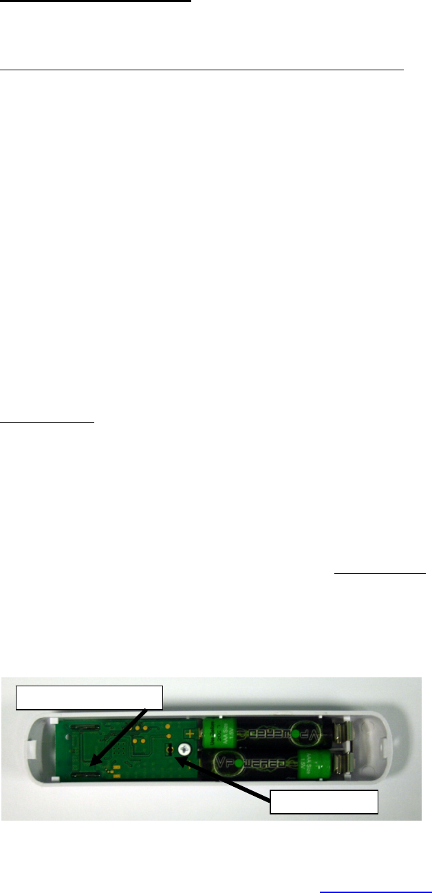
Internal View
The additional following documents are available at: www.viconics.com
• Information on installation & commissioning of the VWA5000W wireless switches on document LIT-VWA5000W-Exx
• Information on installation of the Terminal Equipment Controller (VTR7300), is available on document LIT-VTR7300-PIR-Exx
• PIR Hospitality application information and examples, are available on document: APP-HOSPITALITY-PIR-VTR73-Guide-Exx
• HVAC Fan Coil application information and examples, are available on document: APP-VTR7300-PIR-Exx
• Information on the Wireless models (VTR3xxX5x00W), is available on documents: ITG-VWG-40-BAC-Exx and MAN Wireless Stat
Driver Guide-Exx
Hidden service LED
Hidden switch
3
VWA5000W Wireless Switch Specifications
Power requirements: 3.0 Vdc 2 x AAA batteries. Factory supplied
Operating conditions: 0 °C to 50 °C ( 32 °F to 122 °F )
0% to 95% R.H. non-condensing
Storage conditions: -30 °C to 50 °C ( -22 °F to 122 °F )
0% to 95% R.H. non-condensing
(PENDING) Agency Approvals all models CE: RTTE 1999/5/EC
(PENDING) Agency Approvals Wireless models FCC: Compliant to: Part 15, Subpart C
THIS DEVICE COMPLIES WITH PART 15 OF THE FCC RULES. OPERATION IS SUBJECT TO THE FOLLOWING TWO
CONDITIONS: (1) THIS DEVICE MAY NOT CAUSE HARMFUL INTERFERENCE, AND (2) THIS DEVICE MUST ACCEPT
ANY INTERFERENCE RECEIVED, INCLUDING INTERFERENCE THAT MAY CAUSE UNDESIRED OPERATION.
THIS DEVICE COMPLIES WITH INDUSTRY CANADA LICENSE-EXEMPT RSS STANDARD(S). OPERATION IS
SUBJECT TO THE FOLLOWING TWO CONDITIONS: (1) THIS DEVICE MAY NOT CAUSE INTERFERENCE, AND (2)
THIS DEVICE MUST ACCEPT ANY INTERFERENCE, INCLUDING INTERFERENCE THAT MAY CAUSE UNDESIRED
OPERATION OF THE DEVICE.
NOTE: THE MANUFACTURER IS NOT RESPONSIBLE FOR ANY RADIO OR TV INTERFERENCE CAUSED BY
UNAUTHORIZED MODIFICATIONS TO THIS EQUIPMENT. SUCH MODIFICATIONS COULD VOID THE USER'S
AUTHORITY TO OPERATE THE EQUIPMENT
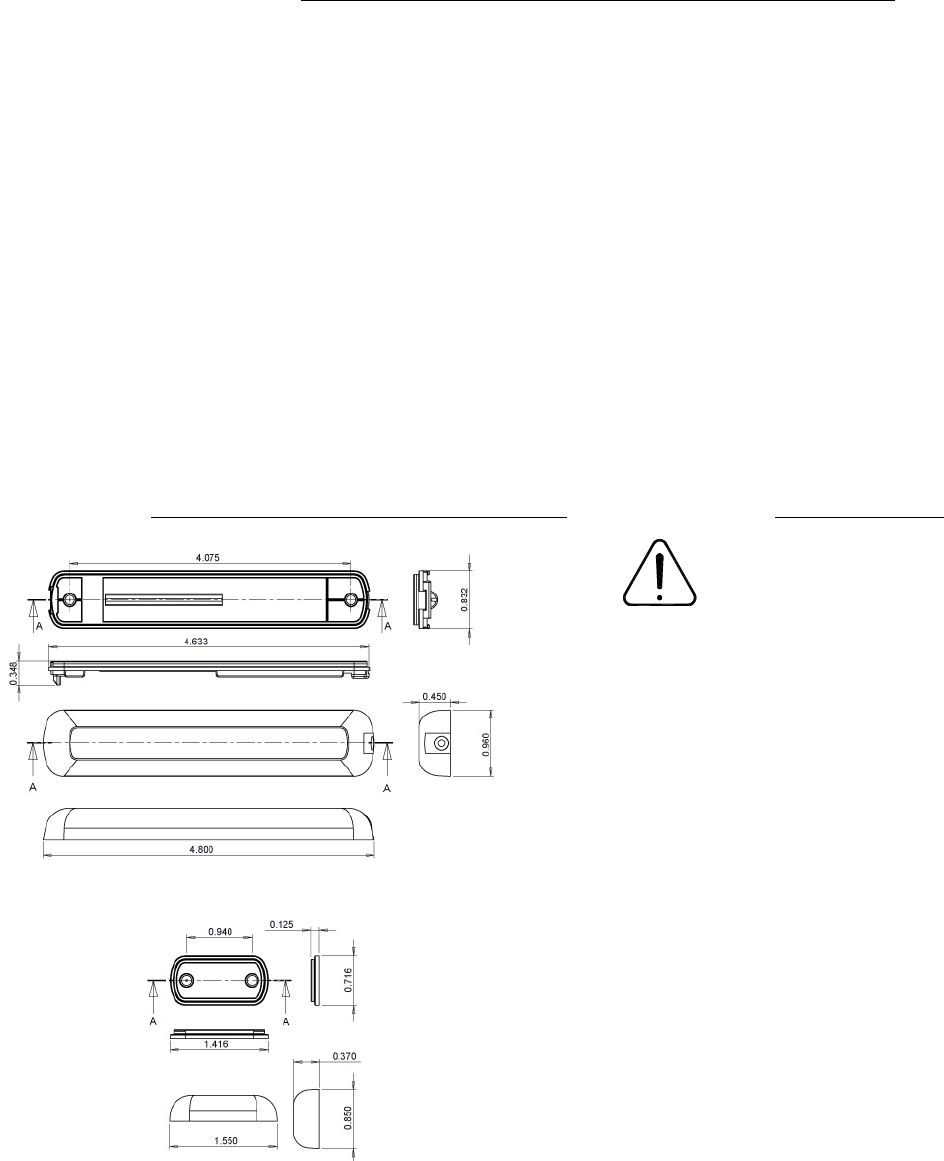
Drawing & Dimensions
Switch & Switch Base Dimensions
Magnet & Magnet Base Dimensions
Important Notice
All VWA5000W series
devices are for use as
operating controls only
and are not safety
devices. These instruments have
undergone rigorous tests and
verifications prior to shipment to
ensure proper and reliable operation in
the field. Whenever a control failure
could lead to personal injury and/or
loss of property, it becomes the
responsibility of the user / installer /
electrical system designer to
incorporate safety devices ( such as
relays, flow switch, thermal
protections, etc…) and/or alarm
system to protect the entire system
against such catastrophic failures.
Tampering of the devices or miss
application of the device will void
warranty.