Viconics Electronics VWAP Wireless door and window switch User Manual
Viconics Electronics Inc. Wireless door and window switch Users Manual
Users Manual
1
Wireless Door/Window Switch
SED - WIN/SED - DOR
Wireless Door and Window Switch
Installation Guide
CONTENTS
Installation 2
Self Testing 2
Location 2
Operation Overview 3
Model Chart 3
Pairing Process Procedure 4
Configuring Actions 4
Using SERx300 Controllers for Stand-alone Systems 4
Using SERx300 Controllers for Networked Systems 6
Important Notes Before Starting Pairing Procedure 7
Pairing – Associating Switches with Controllers 8
Multiple Switch Configuration 8
Troubleshooting Guide 9
Status and Monitoring 9
Battery Status 10
Specifications 10
Drawing and Dimensions 11
Marking Templates for Mounting 12
SED - WIN and SED - DOR 2
Wireless Door/Window Switch
All brand names, trademarks and registered trademarks are the property of their respective owners. Information contained within this document is subject to change without notice.
Schneider Electric One High Street, North Andover, MA 01845 USA Telephone: +1 978 975 9600 Fax: +1 978 975 9674 http://www.schneider-electric.com/buildings
II-SE8000-SEDWINDOR-US.EN.10.2013.v1 October 2013
© 2013 Schneider Electric. All rights reserved.
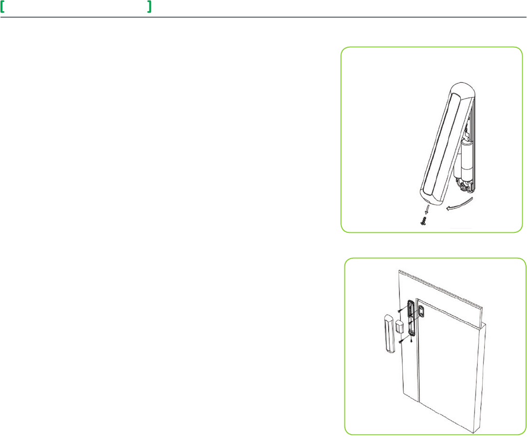
Figure-1 Open cover
Figure-2 Install Switch and Magnet Bases
INSTALLATION SED - WIN/SED - DOR
Installation
1. Remove cover by pulling on side where security screw was mounted
(Figure-1).
2. Remove cover of magnet unit.
3. Read FCC ID and IC label inside removed cover.
4. Cut out mounting template (end of this manual) for install. Do not place it
on hinge side of door unless self tested.
5. Locate template and mark four holes for self-tapping screws.
6. Use self-tapping screws to install both switch and magnet base
(Figure-2).
7. Follow pairing process before installing switch and magnet units.
8. After pairing process is successful, install switch and magnet units.
9. Install security screw on switch.
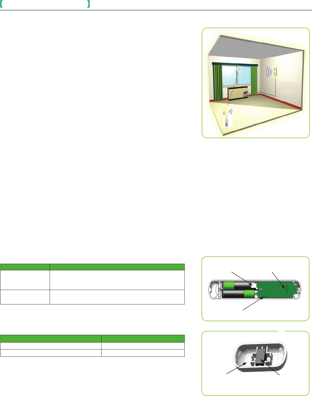
Self Testing
For best practice, the configuration of the wireless switch and magnet unit
should be configured as shown. Use mounting template at the end of this
document for installation. Other configurations can be used, such as
placing devices on top of door, placed horizontally. Always self-test wireless
switch to ensure it works correctly.
Location
• Never install switch unit on moving part (door or window).
• Install only magnet unit on moving part (door or window).
• Never install in direct sun.
• Ensure minimum distance between any wireless node and any WiFi devices
is at least 3 feet (1m).
Notes
• Electronic controls are static sensitive devices. Discharge yourself properly
before manipulating and installing device.
• A short circuit or wrong wiring may permanently equipment.
• All SED-WIN and SED-DOR series controls are designed for use as
operating controls only and are not safety devices. These instruments have
undergone rigorous tests and verification prior to shipping to ensure proper
and reliable operation in the field. Whenever a control failure could lead
to personal injury and or loss of property, it becomes the responsibility of
the user, installer, electrical system designer to incorporate safety devices
(relays, flow switch, thermal protections), or an alarm system to protect
the entire system against catastrophic failures. Tampering with devices or
unintended application of devices results in void of warranty.
• See data sheet for operating and storage conditions.
• Any occurring condensation can damage wireless switch.
• Respect polarity when replacing batteries. Reversing polarity of
batteries can damage wireless switch.
SED - WIN and SED - DOR 3
Wireless Door/Window Switch
All brand names, trademarks and registered trademarks are the property of their respective owners. Information contained within this document is subject to change without notice.
Schneider Electric One High Street, North Andover, MA 01845 USA Telephone: +1 978 975 9600 Fax: +1 978 975 9674 http://www.schneider-electric.com/buildings
II-SE8000-SEDWINDOR-US.EN.10.2013.v1 October 2013
© 2013 Schneider Electric. All rights reserved.
Operation Overview
SED-WIN and SED-DOR series Zigbee Pro™ wireless switches are used with
wireless versions of SERx3XX Series Fan Coil Terminal Equipment Controllers.
A typical hospitality application SERx3xx wall terminal equipment
controller has an on-board PIR sensor. Wireless switches monitor opening
and closing of doors and windows. Wireless door switches used with local
SERx3xx PIR cover provide advanced local occupancy routines allowing for
increased energy savings during occupied hours without sacrificing
occupant comfort.
Wireless window switches monitor outside windows and/or opening/closing of
patio/balcony doors, which prevents unnecessary energy consumption.
Applications of SERx3xx Series Fan Coil Terminal Equipment
Controllers with SED-WIN and SED-DOR series Zigbee Pro™ wireless switches
can be used in network ready mode, with or without integration to a central
management system. This allows for advanced functions such as central reser-
vation occupancy functions.
A combination of up to twenty SED-WIN and SED-DOR door and/or window
switches can be used simultaneously with a single device. The SED-WIN and
SED-DOR switches are factory delivered with 2 AAA batteries and can be
installed, configured, and used right out of the box. Due to extremely small cur-
rent consumption of the switches, the expected battery life is
approximately 10 years.
No tools are required for commissioning or servicing the door switch. A very
simple interface with an on-board LED and hidden switch provides the required
functions for local interaction. Local information for battery life and connectivity
(heartbeat) are provided at the SERx3xx Series Fan Coil
Terminal Equipment Controller local display level, or through the Zigbee Pro™
wireless network. Each switch is also factory supplied with a magnet, locking
security tamper proof screw, and self tapping mounting screws for installation.
Model Chart
PART NUMBER DESCRIPTION
SED-WIN-P-5000
Wireless Window Switch
(Patio and balcony doors)
Complete with magnet, batteries, and required mounting hardware.
SED-DOR-P-5000 Wireless Door Switch
Complete with magnet, batteries, and required mounting hardware.
Verify if device is wireless window switch or wireless door switch:
Remove battery for 60 seconds and then insert again. Power cycle switch and
verify LED blinking pattern to confirm if it is a window switch or door switch.
Part Number Number of Blinks
Window Switch (SED-WIN-P-5000) 2 blinks
Door Switch (SED-DOR-P-5000)3 blinks
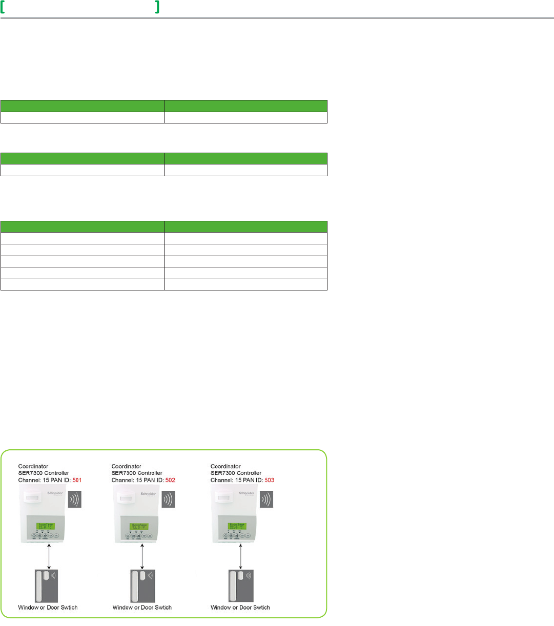
WARNING: Respect polarity when replacing batteries or the switch may be
damaged. The (+) and (–) terminals are indicated on the board.
NOTE: Magnet is located on opposite side of security screw.
LED
(switch side)
Pull Tab
(remove to power
up
switch.)
Hidden
Switch
Figure-3 Wireless Switch Components
Figure-4
Magnet Components and Proper Magnet Orientation
Housing Magnet
SED - WIN and SED - DOR 4
Wireless Door/Window Switch
All brand names, trademarks and registered trademarks are the property of their respective owners. Information contained within this document is subject to change without notice.
Schneider Electric One High Street, North Andover, MA 01845 USA Telephone: +1 978 975 9600 Fax: +1 978 975 9674 http://www.schneider-electric.com/buildings
II-SE8000-SEDWINDOR-US.EN.10.2013.v1 October 2013
© 2013 Schneider Electric. All rights reserved.
Pairing Process Procedure
NOTE: See SER/SE installation manual for details on PAN ID parameter.
PAN ID for Centralized Networked Applications with MPM
SER8300 Series SE 72 / 73 Series*
1 - 500 1 - 250
PAN ID for Stand-alone Applications with no MPM
SER8300 Series SE 72 / 73 Series*
501 - 1000 251 - 500
Note: SE7000 Room Controllers are only compatible if a network with a Coordinator is
present.
Configuring Actions
Short Switch Duration Result
Approximately 1 second Enter Pairing Mode (page 8)
Approximately 1 second (after being paired) Displays MAC address (page 8)
4+ seconds and less than 10 seconds Battery Status (page 13 )
10+ seconds and less than 20 seconds Diagnostic Mode (page 12)
20+ seconds Resets Switch
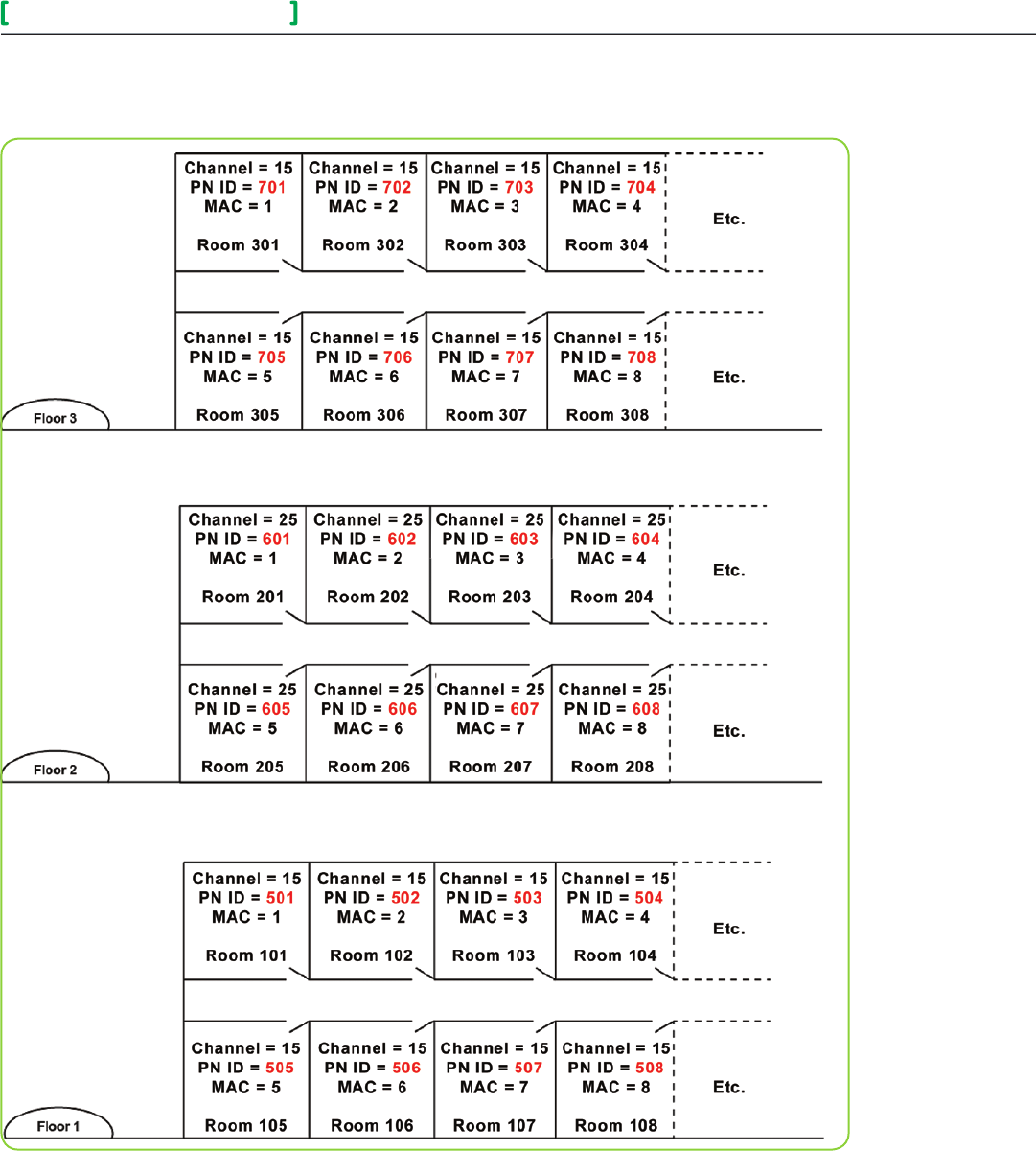
Using SER8300 Controllers for Stand-alone Systems
When PAN ID is used with Range of 501 - 1000 for Stand-Alone Systems
In this application, the SER8300 controller(s) are the coordinators to their own
systems and are network masters for each wireless switch reporting to them. A
unique network is needed for proper functionality according to the following:
•WirelesscontrollerfactorydefaultChannelandPANID=controller(s)ofine.
•EachSER8300controllerisitsownnetworkcoordinator.
•RangeofPANIDonallcontrollerstouseis501-1000.Thisrangeisreserved
for stand-alone system operation.
Notes:
• Each SER8300 Controller uses a unique PAN ID and/or Channel settings.
• If all available PAN ID’s are used (501-1000), use a different channel.
• Up to 20 switches can be linked to each SER8300 Controller.
SED - WIN and SED - DOR 5
Wireless Door/Window Switch
All brand names, trademarks and registered trademarks are the property of their respective owners. Information contained within this document is subject to change without notice.
Schneider Electric One High Street, North Andover, MA 01845 USA Telephone: +1 978 975 9600 Fax: +1 978 975 9674 http://www.schneider-electric.com/buildings
II-SE8000-SEDWINDOR-US.EN.10.2013.v1 October 2013
© 2013 Schneider Electric. All rights reserved.
Floor Plan Stand-Alone Systems with SER8300 Controllers
This example shows a typical floor plan of a unique network for a stand-alone system.
SED - WIN and SED - DOR 6
Wireless Door/Window Switch
All brand names, trademarks and registered trademarks are the property of their respective owners. Information contained within this document is subject to change without notice.
Schneider Electric One High Street, North Andover, MA 01845 USA Telephone: +1 978 975 9600 Fax: +1 978 975 9674 http://www.schneider-electric.com/buildings
II-SE8000-SEDWINDOR-US.EN.10.2013.v1 October 2013
© 2013 Schneider Electric. All rights reserved.
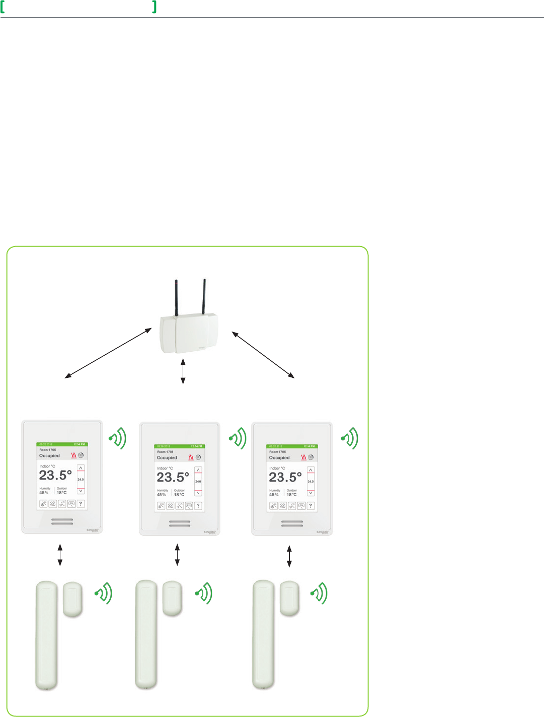
PAN ID used with a Range of 1 to 500 for Networked Systems
In this application, any controller(s) are routers to the system. The MPM is
the coordinator to the system as the MPM is the network master for any
controller(s) reporting to them.
• WirelesscontrollerfactorydefaultChannelandPANID=controller(s)
offline.
• MPM is network coordinator.
• SER8300/SE7000 controllers act as a router.
• Range of PAN ID on all controllers use 1 - 500. Reserved for networked
system operation.
Notes:
• Each controller uses same PAN ID and Channel as MPM coordinator.
• MPM supports network integration for required GUI/System/Status
objects.
• Up to 20 switches can be linked to each SER8300/SE7000 Controller.
Coordinator Channel, 15 PAN ID: 250
SE8000 Controller
Channel, 15 PAN ID: 250
SE8000 Controller
Channel, 15 PAN ID: 250
SE8000 Controller
Channel, 15 PAN ID: 250
Window or Door Switch Window or Door Switch Window or Door Switch

SED - WIN and SED - DOR 7
Wireless Door/Window Switch
All brand names, trademarks and registered trademarks are the property of their respective owners. Information contained within this document is subject to change without notice.
Schneider Electric One High Street, North Andover, MA 01845 USA Telephone: +1 978 975 9600 Fax: +1 978 975 9674 http://www.schneider-electric.com/buildings
II-SE8000-SEDWINDOR-US.EN.10.2013.v1 October 2013
© 2013 Schneider Electric. All rights reserved.
Before Starting Pairing Procedure
Verify the following parameters on the SER8300 controller are set correctly to
avoid failure.
PAN ID
Personal Area
Network Identification
Defaultvalue=0
Range: 0 -1000
This parameter only appears when a wireless network adapter is
present. If the Terminal Equipment Controller is installed as a stand-
alone unit or with a BACnet™ or Echelon™ adapter, this parameter is
not used or displayed.
The default value of 0 is not a valid PAN ID.
The valid range of available PAN ID is from 1 - 1000.
Range 1 - 500 is for centralized networked applications using a MPM.
Range 501 - 1000 is for stand-alone applications where no MPM with
wireless stat driver is used.
Channel
Channel selection
Defaultvalue=10
Range: 10 - 26
This parameter only appears when a wireless network adapter is
present. If the Terminal Equipment Controller is installed as a stand-
alone unit or with a BACnet™ or Echelon™ adapter, this parameter is
not used or displayed.
Schneider-Electric recommends using only channels 15 and 25 only.
The default value of 10 is not a valid channel. The valid range of
available channel is from 11 to 26.
SED - WIN and SED - DOR 8
Wireless Door/Window Switch
All brand names, trademarks and registered trademarks are the property of their respective owners. Information contained within this document is subject to change without notice.
Schneider Electric One High Street, North Andover, MA 01845 USA Telephone: +1 978 975 9600 Fax: +1 978 975 9674 http://www.schneider-electric.com/buildings
II-SE8000-SEDWINDOR-US.EN.10.2013.v1 October 2013
© 2013 Schneider Electric. All rights reserved.
Pairing Associating Switches with Controllers
1. Remove pull tab from battery holder to power-up switch.
2. Verify or set configuration parameter BI1 or BI2 to None to erase current
associated devices.
3. Set configuration parameter BI1 to Window and BI2 to DoorDry.
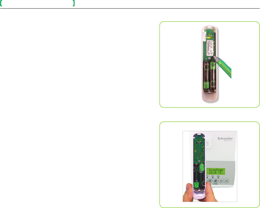
4. To reset wireless switch to its factory default settings if previously
associated, short switch and hold for 20+ seconds. 5 short blinks will
confirm reset (see Figure-5).
5. Short switch once for less than 3 seconds and bring switch to left of con-
troller where COM module is located.
6. Hold switch as close as possible to controller during pairing process (see
Figure-6).
7. LED displays one long blink followed by one short blink to indicate switch
is in pairing mode.
8. LED displays 2 short blinks in succession. Make sure to place switch
closely to COM module of controller.
9. LED displays five short blinks to indicate switch is paired.
10. Quickly short switch and LED displays a blinking pattern matching the cor-
responding MAC address:
Example:MAC=43ifLEDshows4shortblinksfollowedbyapauseand
another 3 short blinks.
Multiple Switch Configuration
In a multiple switch configuration, up to 20 switches can be linked to one
controller. Repeat steps 5 to 9 in pairing process procedure to add multiple
wireless switches.
When a multiple switch configuration is modified, such as removing a switch, a
reset is required according to the following:
1. To reset wireless switch to its factory default settings, short switch and
hold for 20+ seconds. Five short blinks confirm reset.
2. Set configuration parameter BI1 or BI2 to None and then back to BI1 or
BI2 to erase removed wireless switch.
Figure-6 Switch/Controller Proximity During Pairing
Figure-5 Shorting the Switch

SED - WIN and SED - DOR 9
Wireless Door/Window Switch
All brand names, trademarks and registered trademarks are the property of their respective owners. Information contained within this document is subject to change without notice.
Schneider Electric One High Street, North Andover, MA 01845 USA Telephone: +1 978 975 9600 Fax: +1 978 975 9674 http://www.schneider-electric.com/buildings
II-SE8000-SEDWINDOR-US.EN.10.2013.v1 October 2013
© 2013 Schneider Electric. All rights reserved.
Troubleshooting Guide
NOTE: Restart pairing procedure if wireless switch is not yet paired.
Condition Possible Cause Solution
Wireless switch not activating Batteries not installed properly Correctly install batteries by respecting polarity
Switch does not function
properly Not installed correctly See page 2 and mounting template at
the end of this document
Always displaying
Low Battery A switch was removed See Multiple Switch Configuration
Wireless switch not pairing with
device
Configuration parameters must
be reset
Set configuration parameters BI1 and BI2 to None and then reset
them to Window and/or BI2 to DoorDry
Wireless switch must be reset Jump switch for 20+ seconds and restart pairing
Incorrect PAN ID or Channel Set to appropriate PAN ID or Channel
Status and Monitoring
Once the switch is commissioned, it can be monitored by the status LED when diagnostic mode is
enabled. Once diagnostic mode is enabled, when the magnet is placed near the switch, the LED
stays off. Conversely, when the magnet is away from the switch, the LED stays on.
The switch status can also be viewed as a present value on the network front end.
Enter/enable diagnostic mode
Short Switch Duration Duration of Diagnostic Mode
10+ seconds and less than 20 seconds 2 minutes
Alarms
If a low battery alarm is detected, it automatically shows at the end of the wall controller scrolling
status display. When an alarm message shows, the backlit screen on the controller illuminates at
the same time as the message, and shuts off during the rest of the status display.
Low Batt
Indicates an attached wireless switching device (door or window contact) has a low
battery condition.
Only functional when used with a wireless communication adapter, OR, a switch was
removed.
Important: It is recommended batteries of all switches under a single
controller be replaced when this alarm shows.
SED - WIN and SED - DOR 10
Wireless Door/Window Switch
All brand names, trademarks and registered trademarks are the property of their respective owners. Information contained within this document is subject to change without notice.
Schneider Electric One High Street, North Andover, MA 01845 USA Telephone: +1 978 975 9600 Fax: +1 978 975 9674 http://www.schneider-electric.com/buildings
II-SE8000-SEDWINDOR-US.EN.10.2013.v1 October 2013
© 2013 Schneider Electric. All rights reserved.
Battery Status
To verify battery strength of the wireless switch, jump switch
for 4+ seconds and less than 10 seconds and ensure a blinking pattern shows. After the blinking pattern
shows, the switch enters diagnostic mode for 10 seconds.
Number of Blinks Indication
1 blink Replace batteries
2 blinks Replace batteries soon
3 blinks Battery strength is fair
4 blinks Battery strength is good
5 blinks Battery strength is excellent
Important: Respect polarity when replacing batteries. Reversing polarity of batteries can damage wireless
switch.
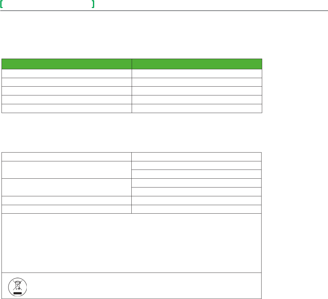
Specifications
Power requirements 3.0 VDC 2 x AAA batteries. Factory supplied
Operating conditions
0 °C - 50 °C ( 32 °F to 122 °F )
0% - 95% R.H. non-condensing
Storage conditions
-30 °C - 65 °C ( -22 °F to 122 °F )
0% - 95% R.H. non-condensing
Agency approvals for all models CE: RTTE 1999/5/EC
Agency approvals for wireless models FCC compliant to: Part 15, Subpart C
THIS DEVICE COMPLIES WITH PART 15 OF THE FCC RULES. OPERATION IS SUBJECT TO THE FOLLOWING TWO CONDITIONS: (1)
THIS DEVICE MAY NOT CAUSE HARMFUL INTERFERENCE, AND (2) THIS DEVICE MUST ACCEPT ANY INTERFERENCE RECEIVED,
INCLUDING INTERFERENCE THAT MAY CAUSE UNDESIRED OPERATION.
NOTE: THE MANUFACTURER IS NOT RESPONSIBLE FOR ANY RADIO OR TV INTERFERENCE CAUSED BY UNAUTHORIZED
MODIFICATIONS TO THIS EQUIPMENT. SUCH MODIFICATIONS COULD VOID THE USER’S AUTHORITY TO OPERATE THE
EQUIPMENT
Check with your local government for instruction on disposal of this product
SED - WIN and SED - DOR 11
Wireless Door/Window Switch
All brand names, trademarks and registered trademarks are the property of their respective owners. Information contained within this document is subject to change without notice.
Schneider Electric One High Street, North Andover, MA 01845 USA Telephone: +1 978 975 9600 Fax: +1 978 975 9674 http://www.schneider-electric.com/buildings
II-SE8000-SEDWINDOR-US.EN.10.2013.v1 October 2013
© 2013 Schneider Electric. All rights reserved.
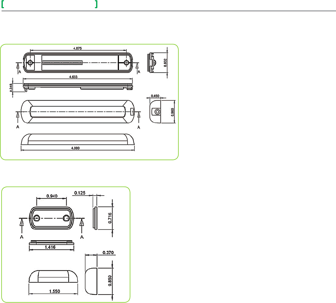
Drawing and Dimensions
The illustration below shows dimensions for the switch and switch base.
The illustration below shows dimensions for the magnet and magnet base.
SED - WIN and SED - DOR 12
Wireless Door/Window Switch
All brand names, trademarks and registered trademarks are the property of their respective owners. Information contained within this document is subject to change without notice.
Schneider Electric One High Street, North Andover, MA 01845 USA Telephone: +1 978 975 9600 Fax: +1 978 975 9674 http://www.schneider-electric.com/buildings
II-SE8000-SEDWINDOR-US.EN.10.2013.v1 October 2013
© 2013 Schneider Electric. All rights reserved.
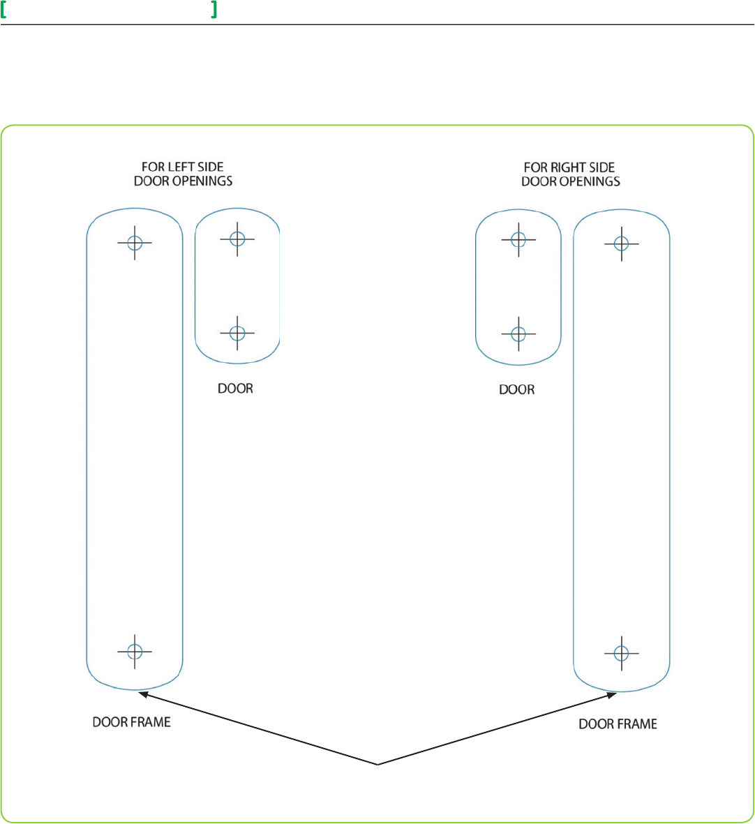
Location of Security Screws
Marking Templates for Mounting