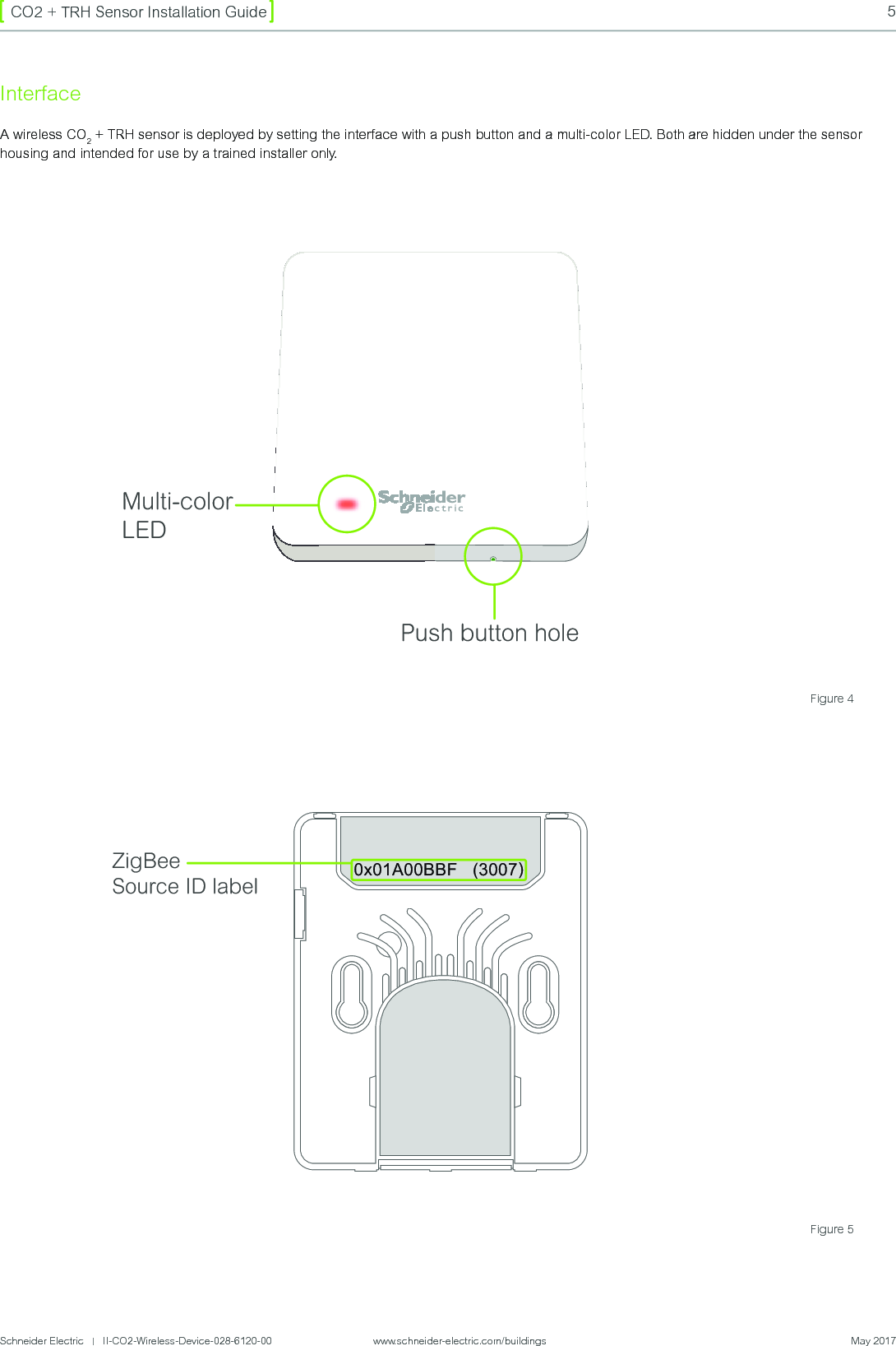
Viconics Electronics VZG Wireless room sensor User Manual Wireless CO2 TRH Sensor

Viconics Electronics Inc. Wireless room sensor Wireless CO2 TRH Sensor

User Manual

Wireless CO2 + TRH SensorInstallation GuideVersion 1
2CO2 + TRH Sensor Installation GuideSchneider Electric   |   II-CO2-Wireless-Device-028-6120-00                www.schneider-electric.com/buildings  May 2017IntroductionDescriptionThe wireless CO2 + TRH (Carbon Dioxide + Temperature and Relative Humidity) sensor is a wall mounted device with ambient (indoor) comfort monitoring and HVAC control applications. The sensor can measure ambient temperature, relative humidity and depending on the model - CO2 concentration. The measured data is communicated wirelessly using ZigBee Green Power protocol to a Room/ Zone controller.The sensor integrates an ultra-low power CO2  and a digital temperature(T) and relative humidity (RH) sensor.The Human Machine Interface (HMI) of the sensor is based on a bi-color Light-Emitting Diode (LED) and a pushbutton, both covered by a plastic housing. A small tool or stylus is needed to push the button located through a small hole. The LED flashes through the top plastic cover and is not visible when not active. All communication with the device is done wirelessly via a bidirectional ZigBee Green Power protocol after a successful pairing/commissioning procedure. The sensor is powered by an embedded AA size lithium-thionyl chloride spiral battery (not rechargeable, not removable). The battery capacity allows up to 10 years of  operating time at nominal conditions. The device must be replaced and recycled when the battery is discharged.Box ContentsThe wireless CO2 + TRH sensor box contains the following:•  Wireless CO2 + TRH sensor or TRH sensor•  Wall-mounting bracket•  Two screws for wall-mounting bracket•  Installation guideSystem RequirementsIf used in conjunction with a Schneider Electric Room Controller, the wireless CO2 + TRH  sensor requires a SE8000 Series Room Controller running firmware version 1.7 or higher.The CO2 + TRH sensor is not compatible with SE7000 Series Room Controllers.Please note the sensor is available in two variations:1.  CO2 + TRH sensor (SED-CO2-G-5045)2.  TRH only sensor (SED-TRH-G-5045)All information related herein applies to both models, except for CO2 functionalities which are only available on the CO2 + TRH sensor.
Schneider Electric   |   II-CO2-Wireless-Device-028-6120-00                    www.schneider-electric.com/buildings  May 20173CO2 + TRH Sensor Installation GuideFigure 2InstallationThe wireless CO2 + TRH sensor can be secured directly on a wall or flat surface using double-sided adhesive tape (Fig.2), or by securing the plastic bracket to the wall (Fig.1) and mounting the sensor (Fig. 3). Using the screws is the recommended method.Figure 1Double-sided adhesive tape zoneAttaching A Sensor Using The Wall Bracket1. Using two screws provided, secure wall bracket to wall (Fig. 1).To perform an accurate ambient comfort measurement, the sensor should not be installed in areas exposed to direct sunlight or near doors, windows or areas exposed to air ow.2. Once bracket is secured, slide sensor on bracket using downward motion. 3. Ensure click sound is heard to verify sensor is secured to bracket and ensure side tab of  bracket is aligned with opening on side of sensor (Fig. 3).It is strongly recommended to attach the sensor to the wall by using the two screws. The adhesive in double-sided tape may not be as long-lasting or as strong to support the sensor throughout its lifetime.
4CO2 + TRH Sensor Installation GuideSchneider Electric   |   II-CO2-Wireless-Device-028-6120-00                www.schneider-electric.com/buildings  May 2017Technical CharacteristicsThe sensor is intended for indoor applications. The operating temperature range is 0 – 45°C. For an accurate CO2 concentration measurement the sensor should operate in 0 to 95% RH, non-condensing environment. Sensor Features CO2 Concentration Digital Temperature Relative HumidityOperating Range 0 – 5000 ppm - 10 ~ 85 °C 0 - 100 %Accuracy (typ. @ 25°C) ±50 ppm +/- 3% of reading ± 0.3 °C ± 2%Accuracy (max @ Tmin,max) ± 80 or up to +/- 3% of readings ± 0.4 °C ± 3%Resolution (typ. @ 25°C) ±17 ppm (or up to 1σ @ 1000ppm) 0.01 °C 0.025%Resolution (max @ Tmin,max) ± 50ppm (@Tmax) 0.01 °C 0.025%Radio communication protocol used by the wireless sensor is compliant with the ZigBee Green Power standard supporting bi-directional communication, commissioning and security encryption features. The device is ZigBee 3.0 compliant. Technical DataWireless Technology ZigBee Green PowerOperating Frequency 2.4 GHzTransmission Range (typ)  20m (indoor) / 100m (free eld)Measuring & Transmitting Period (typ) 2,5 - 10 min  or up to 100m (line of sight)Note: Range may vary depending on local interference sources or RF attenuation from building materials.Operating Conditions 0 °C to 50 °C (32 °F to 122 °F)0% – 95 % rH non-condensing environmentStorage Conditions -30 °C to 50 °C (-22 °F to 122 °F)0% – 95 % rH non-condensing environmentProduct Lifespan¹ typ 10 yearsPower Rating 3.6vDC (Non-replaceable battery)Peek Current: 0.1A¹ The battery lifetime depends on measurement and communication parameters setting and can vary depending on sampling rate, communication rate, or environmental operating conditions.Figure 3ZigBee De-mounting the sensor from the wall bracket:To remove the sensor from the wall bracket, press on the side tab as circled in Fig.3 and slide the sensor up and then out.
Schneider Electric   |   II-CO2-Wireless-Device-028-6120-00                    www.schneider-electric.com/buildings  May 20175CO2 + TRH Sensor Installation GuideInterfaceA wireless CO2 + TRH sensor is deployed by setting the interface with a push button and a multi-color LED. Both are hidden under the sensor housing and intended for use by a trained installer only.Multi-colorLEDPush button holeZigBee Source ID label0x01A00BBF   (3007)Figure 4Figure 5
6CO2 + TRH Sensor Installation GuideSchneider Electric   |   II-CO2-Wireless-Device-028-6120-00                www.schneider-electric.com/buildings  May 2017Refer to the information below for detailed sensor operating instructions.Push buttonThe push button can be pressed through a hole from the bottom side of the sensor, with a slim tool (Figure 4). Each recorded button press is signaled by 2 yellow LED flashes.•  Short pushOne short push starts the commissioning procedure if  the sensor is in the decommissioned (energy saving / hibernation) mode. If  the sensor is already commissioned, it will enter “demo mode” for a 5min timeout interval.•  Long pushOne long push puts the sensor into decommissioned / hibernate mode. The long push is confirmed by one red LED flash roughly 1 second after 2 yellow LED push signaling flashes. After a red LED signal, the button should be released in order to prevent another unintended short push detection.Multi-colour LEDThe multicolor LED is hidden under the top plastic cover, positioned on left (Figure 4).  In normal state the LED is off in order to conserve battery life. It is only used to signal the following special events:•  2  YELLOW flashes confirm each button push taken into account by the sensor.•  1  RED flash acknowledges a long push. The decommissioning procedure and a sensor reset will be executed, then the sensor will enter hibernation mode.•  3  RED flashes signal a commissioning procedure failure.  The sensor stays in decommissioned / hibernation mode.•  3  GREEN flashes signal a commissioning procedure success. The sensor will enter demo mode for 5 min. This demo mode will automatically timeout after 5 minutes. The sensor then stays in commissioned mode, periodically transmitting the measured values to the receiver.•  1  GREEN flash acknowledges a valid GP command received by the sensor in demo mode. This feature can be used as a feedback to an installer to confirm that the sensor is still in range during the commissioning (it works only in demo mode). In this case the receiver has to be programmed to send an acknowledgement command to the sensor after the sensor data report frames.The multiple LED ashes are executed only in 1/2 second intervals.Factory ModeThe wireless CO2 + TRH sensor is in a deep sleep mode waiting for a button push. No measurements, no radio communications are preformed. Operating ModesCommissioningDuring commissioning the wireless CO2 + TRH sensor will automatically find and pair with the nearest compatible ZigBee Green Power receiver. ZigBee parameters (e.g. operational channel, Src-ID, PAN-ID, security level and key) are exchanged between the sensor and receiver in order to establish a reliable and secure link. During commissioning the sensor is presented as an UNSPECIFIED DEVICE (GP ModelID = 0xFE) with the GP Product ID = 17305 (0x4399) and its unique source ID (SrcID). The SrcID of each sensor is marked on its backside (Figure 5). The receiver should be ZigBee 3.0 compliant. The commissioning procedure can be triggered only from the Decommissioned / Hibernation Mode by a long push of  the button. The commissioning procedure can be resumed through the following steps:1.  Set a ZigBee operational channel (11 - 26) and the PAN-ID of  your network (0xFFFF by default) on your ZigBee 3.0 compliant receiver.2.  Put the receiver into the automatic commissioning mode (opened for the commissioning and accepting the commissioning with GP ModelID = 0xFE and GP Product ID = 17305 devices).3.  On the wireless CO2 + TRH sensor press the push button once to start the bidirectional ZGP commissioning. The button actuating is immediately confirmed by two yellow LED pulses. The sensor then automatically scans all ZigBee channels (channel 11-26) in order to find the nearest ZGP Proxy device (receiver in commissioning mode) and initiates the pairing.4.  Wait approximately 10s – during this time the sensor automatically performs the commissioning. The LED will not flash during this period (even if  you push the button again).5.  Commissioning success is indicated by 3 green LED pulses. You can check measured data reported from the sensor to the receiver.  If  the commissioning fails (indicated by 3 red LED pulses) please ensure the sensor is in Factory Mode and in proximity of the receiver, then repeat the procedure.
Schneider Electric   |   II-CO2-Wireless-Device-028-6120-00                    www.schneider-electric.com/buildings  May 20177CO2 + TRH Sensor Installation GuideCO2  Sensor AutocalibrationPrinciple of operationThe CO2  module inside the wireless CO2 + TRH sensor, is fully calibrated prior to shipping from the factory. Over time, the measurement offset needs to be calibrated to maintain the long term stability of  the sensor. In most applications, this can happen automatically using the built in auto-calibration function. This technique can be used in situations in which sensors will be exposed to typical background levels (400-450ppm) at least once during the auto-calibration period. For example, many buildings will drop quickly to background CO2 levels when unoccupied overnight or at weekends. The auto-calibration function uses the information gathered at these periods to recalibrate.The auto-calibration function uses the lowest point of CO2 concentration to recalibrate the offset. During every measurement cycle, the CO2 sensor stores the latest values, and also the lowest value recorded since the last calibration point.The first 50 measurements after calibration are ignored when calculating the lowest value.Autocalibration default settingThe CO2 sensor is shipped with the auto-calibration feature enabled. There isn’t any CO2 measurement in the Factory Mode before the Commissioning. After the Commissioning all previous CO2 measurement data stored in the sensor is erased.By default the first autocalibration will happen 1 day after the commissioning, and the following auto-calibrations in 8-day intervals.Demo ModeThe data measurement and TX period is temporarily reduced to 5 seconds. The green LED flashes once after each valid ZGP command reception by the sensor. This feature can be used as a feedback to an installer confirming that the sensor is still in the radio range of  the receiver. Remember the sensor can receive a ZGP command only after a measured values report, so maximum green LED flashing rate is 5s. The receiver has to be programmed to send an acknowledgment command to the sensor. The sensor automatically switches to Commissioned Mode once the 5min timeout elapses.Normal ModeThe sensor periodically measures T, rH and CO2 and reports the measured values to the receiver which it is paired with. By default the nominal measurement and Transmission(TX) period is 150s (2min and 30sec). This parameter can be edited by a ZigBee command. The sensor is always sleeping in between two data measurements and TX.  It can be woken up at any time with the push button.When the CO2 concentration drops below the customizable comfort value the transmission period is multiplied by 4. The sensor automatically returns back to nominal transmission period if the CO2 concentration value exceeds the comfort threshold value.This device complies with Part 15 of the FCC Rules. Operation is subject to the following two conditions: • this device may not cause harmful interference • this device must accept any interference received, including interference that may cause undesired operation. Changes or modifications not approved by the manufacturer could void the user’s authority to operate the equipment. This equipment complies with FCC radiation exposure limits set forth for an uncontrolled environment. In order to avoid the possibility of exceeding the FCC radio frequency exposure limits, human proximity to the antenna shall not be less than 20cm during normal operation. This device complies with Industry Canada licence-exempt RSS standard(s). Operation is subject to the following two conditions: • this device may not cause interference • this device must accept any interference, including interference that may cause undesired operation of the device. This equipment complies with IC RSS-102 radiation exposure limits set forth for an uncontrolled environment. This equipment should be installed and operated with minimum distance 20cm between the radiator & your body. Le présent appareil est conforme aux CNR d’Industrie Canada applicables aux appareils radio exempts de licence. L’exploitation est autorisée aux deux conditions suivantes : • l’appareil ne doit pas produire de brouillage • l’utilisateur de l’appareil doit accepter tout brouillage radioélectrique subi, même si le brouillage est susceptible d’en compromettre le fonctionnement.
Technical SupportFor any issues with SmartStruxure Solution or SmartStruxure Lite, contact Schneider ElectricTechnical Support according to your region.North America (NAM) Product Support•  Building Management Systems (BMS): www.nampss.comGlobal Product Support•  Building Management Systems (BMS): productsupport.BMS@schneider-electric.com   https://exchangecommunity.schneider-electric.com/community/bms/smartstruxure-liteSchneider Electric is the global specialist in energy management and automation. With revenues of ~€25 billion in FY2016, our 160,000+ employees serve customers in over 100 countries, helping them to manage their energy and process in ways that are safe, reliable, efficient and sustainable. From the simplest of switches to complex operational systems, our technology, software and services improve the way our customers manage and automate their operations. Our connected technologies reshape industries, transform cities and enrich lives.At Schneider Electric, we call this Life Is On.

Navigation menu