Viessmann Vitodens 200 W B2Ha Technical Manual 5683 718 04
2015-08-26
: Viessmann Viessmann-Vitodens-200-W-B2Ha-Technical-Manual-802279 viessmann-vitodens-200-w-b2ha-technical-manual-802279 viessmann pdf
Open the PDF directly: View PDF ![]() .
.
Page Count: 52
Technical Data Manual
VITODENS
r
200-W
5683 718 - 04 04/2015
Model Nos. and pricing: see Price List
Gas-fired wall-mounted condensing boiler
104 to 530 MBH (30 to 155 kW)
Multi-boiler installation 104 to 4240 MBH
For Natural Gas and Liquid Propane Gas
Product may not be exactly as shown
Vitodens 200-W
Series B2HA Series, Models 100, 112 and 150
Gas-Fired Wall-Mounted Condensing Boiler
with modulating MatriX cylinder burner
for room air independent operation
(using a direct vent system or room air
dependent operation).
H

5683 718 - 04
2
Vitodens 200-W B2HA 100 to 150 Technical Data
Product Information
Vitodens 200-W
2
The benefits at a glance:
■ Best value in its class with new industry-leading
technology and the most standard features.
■ Highest Efficiency - CSA thermal efficiency rating to
ANSI Z.21.13/CSA 4.9 of 94.5%. Energy Star and the
CSA Energy Performance are not applicable for these
models.
■ Lasting performance with industry-leading Viessmann
made SA240 316 Ti stainless steel Inox-Radial heat
exchanger constructed to CSA B51 and ASME Section IV.
■ Low Emission Combustion with Viessmann made
stainless steel MatriX cylinder burner. Factory calibrated.
■ Fast Installation and Reduced Maintenance with Lambda
Pro, industry-first intelligent combustion management
system: Adjusts automatically to gas type and quality.
No fuel conversion kit required.
■ Powerful and User-friendly
Viessmann Vitotronic on-board multi-function outdoor
reset boiler and system control for multi-temperature
space and DHW heating.
Equipped with the industry’s first intelligent combustion
management system and powerful control technology,
the new generation Vitodens 200-W gas-fired wall-mount
condensing boiler delivers unparalleled performance,
reliability and comfort.
■ Expanded Application Range with increased capacity up
to 530 MBH (155 kW). Multi-boiler installation up to
4240 MBH (1240 kW) with up to 8 boilers (models B2HA
100, 112 and 150).
■ Greater Venting Flexibility with increased vent length [up
to 180 ft. (55 m)] and multiple venting options.
- Horizontal or vertical sealed combustion coaxial
venting (field supplied).
- Horizontal, vertical or hybrid sealed combustion
double-pipe venting (field supplied).
- Horizontal or vertical single-wall venting (field
supplied).
■ Compact, Esthetic Product Design and zero clearance
to combustibles.
■ Extremely Quiet Operation; quieter than most
refrigerators.
■ True High-Altitude Operation up to 10,000 ft. (3,000 m)
with simple electronic adjustment.
■ Efficiency up to 98% through intensive condensation.
■ The gas train on the burner meets the requirement
of ASME/CSD-1.
3
5683 718 - 04
Vitodens 200-W B2HA 100 to 150 Technical Data Product Information
3
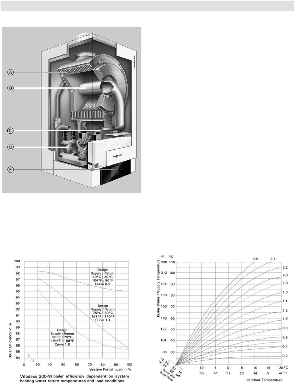
Cross-Section
Products may not be exactly as shown
A Inox-Radial heat exchanger made from stainless steel
– for high operational reliability and a long service life.
Large heating output in the smallest of spaces
B Modulating MatriX cylinder burner for extremely
clean combustion and quiet operation
C Variable speed combustion fan for quiet and
economical operation
D Gas and water connections
E Digital boiler control unit
Delivered condition
Wall mounted gas condensing boiler with Inox-Radial heat
exchanger, modulating MatriX cylinder burner for natural
gas and LPG, plus wall mounting bracket. Vitotronic 200
for weather-compensated operation. Preset for operation
with natural gas. Fully plumbed and wired. White epoxy-
coated casing.
Vitodens 200-W B2HA 100 112, 150
The flue gas temperature is only approximately 9-27º F
(5-15º C) above boiler return temperature (see chart
below).

5683 718 - 04
4
Vitodens 200-W B2HA 100 to 150 Technical Data
Technical Data
Technical Data
4
*A For high altitude installations 5,000 - 10,000 ft. (1500 m - 3000 m), the input for model B2HA 100 and 150 will
have an altitude de-ration of 14% for 5,000 ft. (1500 m) and 29% for 10,000 ft. (3000 m) average of 2.8% /
1,000 ft. (305 m). The input for model B2HA 112 at 10,000 ft. (3000 m) will have an input de-rate of 13%.
*B Net AHRI rating based on piping and pick-up allowance of 1.15.
*1 If the gas supply pressure exceeds the maximum gas supply pressure value, a separate gas pressure regulator
must be installed upstream of the heating system.
*2 See “Waterside Flow” starting on page 10 of this manual.
*3 Output based on 180º F (82º C), 80º F (26º C) system supply/return temperature.
Boiler Model No. B2HA 100*A 112 150*A
Natural Gas / Liquid Propane Gas
CSA input
CSA output *3
MBH
kW
MBH
kW
104-352
30-103
98-333
29-98
113-399
33-117
103-375
30-110
113-530
33-155
103-495
30-145
DOE/AHRI Gross output
Net AHRI Rating *B
MBH
kW
MBH
kW
329
96
286
84
371
109
323
95
490
144
426
125
Heat exchanger surface area ft.2
m2
28.88
2.68
36.78
3.41
36.78
3.41
Min. gas supply pressure
Natural gas
Liquid propane gas
“w.c.
“w.c.
4
10
4
10
4
10
Max. gas supply pressure *1
Natural gas
Liquid propane gas
“w.c.
“w.c.
14
14
14
14
14
14
CSA thermal/combustion efficiency
ANSI Z21,13/CSA 4.9 % 94.5 93.9 93.5
Weight lbs
kg
194
88
298
135
298
135
Boiler water content USG
L
3.4
12.8
4
15
4
15
Boiler max. flow rate *2 GPM
L/h
25
5700
37.9
8600
38
8600
Max. operating pressure
at 210º F (99º C)
psig
bar
60
4
80
5.5
80
5.5
Boiler water temperature
- Adjustable high limit (AHL) range
space heating (steady state)
DHW production
- Fixed high limit (FHL)
ºF
ºC
ºF
ºC
ºF (ºC)
68 to 176
20 to 80
176
80
210 (99)
68 to 180
20 to 82
180
82
210 (99)
68 to 180
20 to 82
180
82
210 (99)
Boiler connections
Boiler heating supply and return
Pressure relief valve
Drain valve
Boiler supply/return for
indirect-fired DHW storage tank
(field supplied)
Gas valve connection
NPTM”
NPTF”
(male
thread)
NPT”
NPTF”
1b
¾
¾
1b
1
2
¾
¾
2
1
2
¾
¾
2
1

5
5683 718 - 04
Vitodens 200-W B2HA 100 to 150 Technical Data Technical Data
5
Technical Data (continued)
*A For high altitude installations 5,000 - 10,000 ft. (1500 m - 3000 m), the input for model B2HA 100 and 150 will
have an altitude de-ration of 14% for 5,000 ft. (1500 m) and 29% for 10,000 ft. (3000 m) average of 2.8% /
1,000 ft. (305 m). The input for model B2HA 112 at 10,000 ft. (3000 m) will have an input de-rate of 13%.
*4 Measured flue gas temperature with a combustion air temperature of 68° F (20° C).
*5 Based on maximum input rate.
*6 Requires 1 inch (25 mm) tubing. See the Installation Instructions of the Vitodens 200-W, B2HA for details.
*7 For side wall vent installations (coaxial system):
Do not exceed max. equivalent length specified in the Installation Instructions of the Vitodens 200-W, B2HA
Venting System.
Do not attempt to common-vent Vitodens 200-W with any other appliance.
Side wall co-axial vent installation must include Viessmann protective screen!
For details refer to the Installation Instructions for the Vitodens 200-W, B2HA Venting System.
*8 Add approximately 2b inches (65 mm) for coaxial vent pipe transition adaptor.
For information regarding other Viessmann System Technology componentry, please reference the documentation
of each respective product.
Boiler Model No. B2HA 100*A 112 150*A
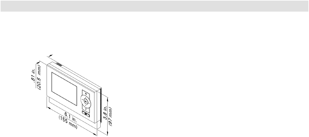
Dimensions
Overall depth
Overall width
Overall height
inches
mm
inches
mm
inches
mm
21
530
19
480
43b
*8 1105
27.1
698
235/8
600
44b
*8 1128
27.1
698
235/8
600
44b
*8 1128
Flue gas *4
Temperature (at boiler return
temperature of 86º F (30º C)
- at rated full load
- at rated partial load
Temperature (at boiler return
temperature of 140º F (60º C)
ºF (ºC)
ºF (ºC)
ºF (ºC)
135 (57)
99 (37)
162 (72)
124 (51)
102 (39)
158 (70)
140 (60)
102 (39)
165 (74)
Max. condensate flow rate *5
for NG and LPG
TS/TR =104/86º F (40/30º C) USG/h
L/h
3.5
13.1
4.35
16.5
5.28
20.0
Condensate connection *6 hose
nozzle
Ø in. ¾-1¾-1¾-1
Boiler flue gas connection *7 Ø
in. (mm) 43/8 (110) 43/8 (110) 43/8 (110)
Combustion air supply
connection (coaxial)
outer
Ø in. (mm) 6 (150) 6 (150) 6 (150)
Sound Rating
- at maximum input
- at minimum input
dB
dB
69
38
57
40
61
40
5683 718 - 04
6
Vitodens 200-W B2HA 100 to 150 Technical Data
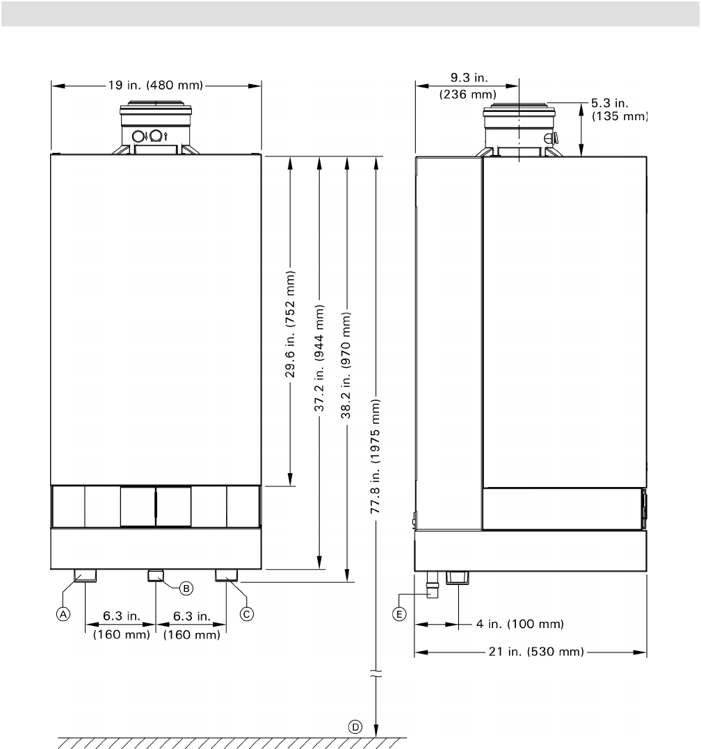
Dimensional Information
Model B2HA 100
Legend
A Boiler Supply
B Gas Connection, 1” NPTF
C Boiler Return
D Recommended height (single boiler system)
E Condensate drain
7
5683 718 - 04
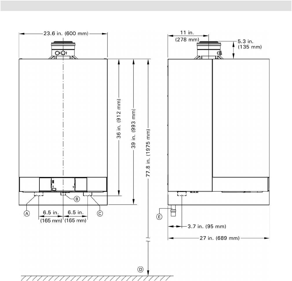
Vitodens 200-W B2HA 100 to 150 Technical Data Dimensional Information
Models B2HA 112, 150
Legend
A Boiler Supply
B Gas Connection, 1” NPTF
C Boiler Return
D Recommended height (single boiler system)
E Condensate drain
5683 718 - 04
8
Vitodens 200-W B2HA 100 to 150 Technical Data
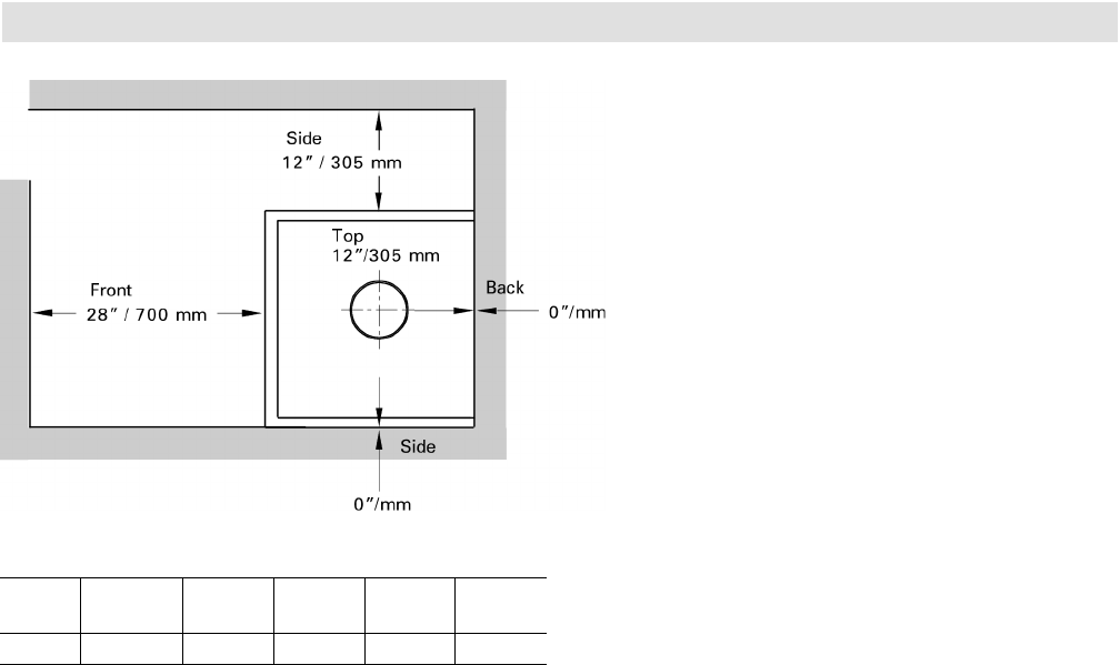
Minimum Clearances
Recommended Minimum Service Clearances
Minimum Clearances to Combustibles
AL= Alcove
CL= Closet
*1 Refer to the Installation Instructions of the Vitodens
200-W, B2HA Venting System for details.
Note: The Vitodens boiler has passed the zero inches vent
clearance to combustibles testing requirements
dictated by the Harmonized Standard ANSI Z21.13.
CSA 4.9.2000 and therefore is listed for zero
clearance to combustibles when vented with a
single wall special venting system (AL-29-4C
material). The zero inches vent clearance to
combustibles for the Vitodens boiler supercedes
the clearance to combustibles listing that appears
on the special venting system label.
Top Front Rear Left Right Vent
pipe *1
0 0 AL, CL 0 0 0 0
9
5683 718 - 04
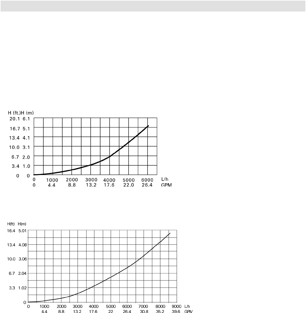
Supply head pressure (water)
Flow rate
Vitodens 200-W B2HA 100 to 150 Technical Data Waterside Flow
Waterside Flow (primary circuit)
Supply head pressure (water)
Flow rate
The Vitodens 200-W, B2HA is designed for closed loop,
forced circulation hot water heating systems only. Use
standard friction loss method for pipe sizing. Observe
boiler maximum and minimum flow rate limitations. If
system flow rate exceeds boiler maximum flow rate
(as stated above), falls below the minimum flow rate
or if system flow rate is unknown, Viessmann strongly
recommends the installation of a low-loss header.
An alternative method may be used, such as primary
secondary piping using closely spaced tees.
A low-loss header offers additional benefits not provided
by a pair of closely spaced tees. Viessmann therefore
strongly recommends and prefers the use of a low-loss
header over closely spaced tees. See pages 28 and 29
for low-loss header information. Once the low-loss header
is connected, the built-in low-loss header logic of the
Vitodens 200-W boiler ensures the required rt across the
system through the sensory communication between the
low-loss header and the boiler.
Pressure drop (primary circuit) for
Vitodens 200-W, B2HA 100
For sizing an on-site circulation system.
Max. flow rate: 25 USGPM (5700 L/h)
Pressure drop (primary circuit) for
Vitodens 200-W, B2HA 112, 150
For sizing an on-site circulation system.
Max. flow rate: 38 USGPM (8600 L/h)

5683 718 - 04
10
Vitodens 200-W B2HA 100 to 150 Technical Data
System Flow Rates
Boiler B2HA 112 maximum flow rate; 38 GPM (8600 L/h)
Boiler B2HA 100 maximum flow rate; 25 GPM (5700 L/h)
Typical System Flow Rates
Boiler B2HA 150 maximum. flow rate; 38 GPM (8600 L/h)
Model B2HA 112 1 boiler 2 boilers 3 boilers 4 boilers 5 boilers 6 boilers 7 boilers 8 boilers
Output (NG/LPG)
MBH 375 750 1125 1500 1875 2250 2625 3000
rt for NG/LPG
20º F rise GPM
(L/h)
37.5
(8500)
75
(17000)
112.5
(25600)
150
(34100)
187.5
(42600)
225
(51100)
262.5
(59600)
300
(68100)
25º F rise GPM
(L/h)
30
(6800)
60
(13600)
90
(20400)
120
(27300)
150
(34100)
180
(40900)
210
(44700)
240
(54500)
30º F rise GPM
(L/h)
25
(5700)
50
(11400)
75
(17000)
100
(22700)
125
(28400)
150
(34100)
175
(39700)
200
(45400)
35º F rise GPM
(L/h)
21.4
(4900)
42.9
(9700)
64.3
(14600)
85.7
(19500)
107.1
(24300)
128.6
(29200)
150
(34100)
171.4
(38900)
40º F rise GPM
(L/h)
18.8
(4300)
37.5
(8500)
56.3
(12800)
75
(17000)
93.8
(21300)
112.5
(25600)
131.3
(29800)
150
(34100)
Model B2HA 150 1 boiler 2 boilers 3 boilers 4 boilers 5 boilers 6 boilers 7 boilers 8 boilers
Output (NG/LPG)
MBH 495 990 1485 1980 2475 2970 3465 3960
rt for NG/LPG
20º F rise GPM
(L/h)
49.5
(11243)
99
(22487)
149
(33731)
198
(44974)
247.5
(56213)
297
(67461)
346.5
(78705)
396
(89949)
25º F rise GPM
(L/h)
39.6
(8994)
79
(17990)
119
(26985)
158
(35979)
198
(44971)
237.6
(53969)
277
(62964)
317
(71959)
30º F rise GPM
(L/h)
33
(7495)
66
(14991)
99
(22487)
132
(29983)
165
(37476)
198
(44974)
231
(52470)
264
(59966)
35º F rise GPM
(L/h)
28
(6424)
57
(12850)
85
(19275)
113
(25700)
141.4
(32122)
170
(38549)
198
(44974)
226
(51399)
40º F rise GPM
(L/h)
25
(5631)
50
(11244)
74
(16865)
99
(22487)
124
(28107)
148.5
(33731)
173
(39352)
198
(44974)
Model B2HA 100 1 boiler 2 boilers 3 boilers 4 boilers 5 boilers 6 boilers 7 boilers 8 boilers
Output (NG/LPG)
MBH 333 666 999 1332 1665 1998 2331 2664
rt for NG/LPG
20º F rise GPM
(L/h)
33.3
(7563)
66.6
(15128)
100
(22692)
133
(30255)
166.5
(37816)
200
(45383)
233
(52947)
266.4
(60510)
25º F rise GPM
(L/h)
26.6
(6051)
53.3
(12102)
80
(18153)
106.6
(24204)
133
(30253)
160
(36307)
187
(42377)
213
(48409)
30º F rise GPM
(L/h)
22.2
(5042)
44.4
(10085)
66.6
(15128)
89
(20170)
111
(25211)
133
(30255)
155.4
(35298)
178
(40341)
35º F rise GPM
(L/h)
19
(4322)
38.1
(8644)
57
(12967)
76
(17289)
95
(21609)
114
(25933)
133
(30255)
152
(34578)
40º F rise GPM
(L/h)
16.7
(3781.6)
33.3
(7564)
50
(11346)
66.6
(15128)
83
(18908)
100
(22692)
117
(26473)
133
(30255)
11
5683 718 - 04
Pump Information
Heating Circuit / Boiler Pumps
Viessmann offers a variety of Grundfos heating circuit
/ boiler pumps which meet typical Vitodens system
installation requirements (see “Heating circuit pump
(field supplied)” or “Boiler pump (field supplied)” in the
Installation Examples starting on page 31). See tables
below for recommended pumps. Refer to the graphs
on page 9 for the proper waterside boiler friction loss
calculations. The following pumps have been selected
based on boiler heat exchanger head loss and boiler
piping to a low-loss header.
IMPORTANT
Model B2HA 112 Flow rate Boiler pressure drop (ft.) Recommended pump option 1 Grundfos
20º F rt37.5 15.0 UPS 32-160/2, 115V, Speed 1 /
UPS 26-150F, 115V, Speed 2
25º F rt30.0 11.3 UPS 32-160/2, 115V, Speed 1 /
UPS 26-150F, 115V, Speed 2
30º F rt25.0 8.8 UPS 32-160/2, 115V, Speed 1 /
UPS 26-150F, 115V, Speed 2
35º F rt21.4 6.5 UPS 32-160/2, 115V, Speed 1 /
UPS 26-99FC, 115V, Speed 3
40º F rt19.5 4.8 UPS 26-99FC, 115V, Speed 2 /
UPS 26-150F, 115V, Speed 1
Flow limitation GPM (L/h) 8600 (37.9)
Model B2HA 150 Flow rate Boiler pressure drop (ft.) Recommended pump option 1 Grundfos
20º F rt-- -- --
25º F rt-- -- --
30º F rt33.0 12.6 UPS 32-160/2, 115V, Speed 1 /
UPS 26-150F, 115V, Speed 3
35º F rt28.3 9.4 UPS 32-160/2, 115V, Speed 1 /
UPS 26-150F, 115V, Speed 2
40º F rt24.8 8.0 UPS 26-99FC, 115V, Speed 3 /
UPS 32-160/2, 115V, Speed 1 /
Flow limitation GPM (L/h) 8600 (37.9)
Model B2HA 100 Flow rate Boiler pressure drop (ft.) Recommended pump option 1 Grundfos
20º F rt-- -- --
25º F rt-- -- --
30º F rt22.2 12.0 UPS 32-160/2, 115V, Speed 1 /
UPS 26-99FC, 115V, Speed 3
35º F rt19.0 8.5 UPS 26-99FC, 115V, Speed 3
40º F rt16.7 6.0 UPS 26-99FC, 115V, Speed 2
Flow limitation GPM (L/h) 5700 (25)
Before using the following pumps for a DHW tank
application, find out the proper pressure drop through the
tank, the required temperature difference through the coil
and system piping head loss of the domestic hot water.
Pump selection must be based on accurate system flow
and pressure drop calculations (incl. DHW sizing).
Vitodens 200-W B2HA 100 to 150 Technical Data

5683 718 - 04
12
Vitodens 200-W B2HA 100 to 150 Technical Data
Low-Loss Header Application
Low-Loss Header Information
Note: for multiple boiler applications when using the Vitodens 200-W, B2HA boilers, refer to the multiple boiler
low-loss distribution manifold installation instructions.
*1 For system rt < 20° F use low-loss header sizes for rt 20° F.
*2 Low-Loss sensor - standard equipment of the cascade control Vitotronic 300-K MW2B:
for use in multiple boiler applications.
Boiler
Model
No. of
Boilers
Boiler
Max.
Flow
Rate
Total
Flow
Rate
Typical System Flow Rates Viessmann
Low-loss
Temp.
Sensor
Required*2
rt *1 °F
(°C)
20
(11)
25
(14)
30
(17)
35
(19.5)
40
(22)
B2HA
100
2 25
(5700)
50
(11400)
System Flow
Rate
LLH Required
LLH Model
GPM
(L/h)
66.6
(15128)
Yes
200/120
53.3
(12102)
Yes
200/120
44.4
(10085)
Yes
160/80
38.1
(8644)
Yes
160/80
33.3
(7564)
Yes
120/80
Yes
B2HA
100
3 25
(5700)
75
(17100)
System Flow
Rate
LLH Required
LLH Model
GPM
(L/h)
100
(22692)
Yes
250/150
80
(18153)
Yes
200/120
66.6
(15128)
Yes
200/120
57
(12967)
Yes
200/120
50
(11346)
Yes
200/120
Yes
B2HA
100
4 25
(5700)
100
(22800)
System Flow
Rate
LLH Required
LLH Model
GPM
(L/h)
133
(30255)
Yes
300/200
106.6
(54204)
Yes
250/150
89
(20170)
Yes
250/150
76
(17289)
Yes
200/120
66.6
(15128)
Yes
200/120
Yes
B2HA
100
5 25
(5700)
125
(28500)
System Flow
Rate
LLH Required
LLH Model
GPM
(L/h)
166.5
(37816)
Yes
300/200
133
(30253)
Yes
300/200
111
(25211)
Yes
250/150
95
(21609)
Yes
250/150
83
(18908)
Yes
250/150
Yes
B2HA
100
6 25
(5700)
150
(34200)
System Flow
Rate
LLH Required
LLH Model
GPM
(L/h)
200
(45383)
Yes
400/200
160
(36307)
Yes
300/200
133
(30255)
Yes
300/200
114
(25933)
Yes
250/150
100
(22692)
Yes
250/150
Yes
B2HA
100
7 25
(5700)
175
(39900)
System Flow
Rate
LLH Required
LLH Model
GPM
(L/h)
233
(52947)
Yes
400/200
187
(42377)
Yes
300/200
155.4
(35298)
Yes
300/200
133
(30255)
Yes
300/200
117
(26473)
Yes
250/150
Yes
B2HA
100
8 25
(5700)
200
(45600)
System Flow
Rate
LLH Required
LLH Model
GPM
(L/h)
266.4
(60510)
Yes
450/250
213
(48409)
Yes
400/200
178
(40341)
Yes
300/200
152
(34578)
Yes
300/200
133
(30255)
Yes
300/200
Yes
Sizing of Low-Loss Header in a Commercial Multiple-Boiler Application
Boiler
Model
No. of
Boilers
Boiler
Max.
Flow
Rate
Total
Flow
Rate
Typical System Flow Rates Viessmann
Low-loss
Temp.
Sensor
Required*2
rt *1 °F
(°C)
20
(11)
25
(14)
30
(17)
35
(19.5)
40
(22)
B2HA
100
1 25
(5700)
25
(5700)
System Flow
Rate
LLH Required
LLH Model
GPM
(L/h)
33.3
(7563)
Yes
120/80
26.6
(6051)
Yes
120/80
22.2
(5042)
Optional
120/80
19
(4322)
Optional
80/60
16.7
(3781.6)
Optional
80/60
Optional
Sizing of Low-Loss Header in a Residential/Commercial Single-Boiler Application
*1 For system rt < 20° F use low-loss header sizes for rt 20° F.
*2 Low-Loss temperature sensor - optional equipment for use in single-boiler applications.

Vitodens 200-W B2HA 100 to 150 Technical Data
13
5683 718 - 04
Low-Loss Header Information
Low-Loss Header Application (continued)
Boiler
Model
No. of
Boilers
Boiler
Max.
Flow
Rate
Total
Flow
Rate
Typical System Flow Rates Viessmann
Low-loss
Temp.
Sensor
Required*2
rt *1 °F
(°C)
20
(11)
25
(14)
30
(17)
35
(19.5)
40
(22)
B2HA
112
2 38
(8600)
76
(17200)
System Flow
Rate
LLH Required
LLH Model
GPM
(L/h)
75
(17034)
Yes
200/120
60
(13627)
Yes
200/120
50
(11356)
Yes
200/120
43
(9734)
Yes
200/120
38
(8517)
Yes
160/80
Yes
B2HA
112
3 38
(8600)
114
(25800)
System Flow
Rate
LLH Required
LLH Model
GPM
(L/h)
113
(25552)
Yes
250/150
90
(20441)
Yes
250/150
75
(17034)
Yes
250/150
64
(14601)
Yes
250/150
56
(12776)
Yes
200/120
Yes
B2HA
112
4 38
(8600)
152
(34400)
System Flow
Rate
LLH Required
LLH Model
GPM
(L/h)
150
(34069)
Yes
300/200
120
(27255)
Yes
300/200
100
(22712)
Yes
250/150
86
(19468)
Yes
250/150
75
(17034)
Yes
200/120
Yes
B2HA
112
5 38
(8600)
190
(43000)
System Flow
Rate
LLH Required
LLH Model
GPM
(L/h)
188
(42586)
Yes
300/200
150
(34069)
Yes
300/200
125
(28391)
Yes
300/200
107
(24335)
Yes
250/150
94
(21293)
Yes
250/150
Yes
B2HA
112
6 38
(8600)
228
(51600)
System Flow
Rate
LLH Required
LLH Model
GPM
(L/h)
225
(51103)
Yes
400/200
180
(40882)
Yes
400/200
150
(34069)
Yes
300/200
129
(29202)
Yes
300/200
113
(25552)
Yes
300/200
Yes
B2HA
112
7 38
(8600)
266
(60200)
System Flow
Rate
LLH Required
LLH Model
GPM
(L/h)
263
(59620)
Yes
450/250
210
(47696)
Yes
400/200
175
(39747)
Yes
300/200
150
(34069)
Yes
300/200
131
(29810)
Yes
300/200
Yes
B2HA
112
8 38
(8600)
304
(68800)
System Flow
Rate
LLH Required
LLH Model
GPM
(L/h)
300
(68137)
Yes
450/250
240
(54510)
Yes
400/200
200
(45425)
Yes
400/200
171
(38936)
Yes
300/200
150
(34069)
Yes
300/200
Yes
Note: for multiple boiler applications when using the Vitodens 200-W, B2HA boilers, refer to the multiple boiler
low-loss distribution manifold installation instructions.
*1 For system rt < 20° F use low-loss header sizes for rt 20° F.
*2 Low-Loss sensor - standard equipment of the cascade control Vitotronic 300-K MW2B:
for use in multiple boiler applications.
Sizing of Low-Loss Header in a Commercial Multiple-Boiler Application
Boiler
Model
No. of
Boilers
Boiler
Max.
Flow
Rate
Total
Flow
Rate
Typical System Flow Rates Viessmann
Low-loss
Temp.
Sensor
Required*2
rt *1 °F
(°C)
20
(11)
25
(14)
30
(17)
35
(19.5)
40
(22)
B2HA
112
1 38
(8600)
38
(8600)
System Flow
Rate
LLH Required
LLH Model
GPM
(L/h)
37.5
(8517)
Yes
160/80
30
(6814)
Optional
120/80
25
(5678)
Optional
120/80
21.4
(4867)
Optional
120/80
19.5
(4429)
Optional
80/60
Optional
Sizing of Low-Loss Header in a Residential/Commercial Single-Boiler Application
*1 For system rt < 20° F use low-loss header sizes for rt 20° F.
*2 Low-Loss temperature sensor - optional equipment for use in single-boiler applications.

Vitodens 200-W B2HA 100 to 150 Technical Data
5683 718 - 04
14
Low-Loss Header Application (continued)
Low-Loss Header Information
Boiler
Model
No. of
Boilers
Boiler
Max.
Flow
Rate
Total
Flow
Rate
Typical System Flow Rates Viessmann
Low-loss
Temp.
Sensor
Required*2
rt *1 °F
(°C)
20
(11)
25
(14)
30
(17)
35
(19.5)
40
(22)
B2HA
150
2 38
(8600)
76
(17200)
System Flow
Rate
LLH Required
LLH Model
GPM
(L/h)
99
(22487)
Yes
250/150
79
(17990)
Yes
200/120
66
(14991)
Yes
200/120
57
(12850)
Yes
200/120
50
(11244)
Yes
200/120
Yes
B2HA
150
3 38
(8600)
114
(25800)
System Flow
Rate
LLH Required
LLH Model
GPM
(L/h)
149
(33731)
Yes
300/200
119
(26985)
Yes
300/200
99
(22487)
Yes
250/150
85
(19275)
Yes
250/150
74
(16865)
Yes
200/120
Yes
B2HA
150
4 38
(8600)
152
(34400)
System Flow
Rate
LLH Required
LLH Model
GPM
(L/h)
198
(44974)
Yes
400/200
158
(35979)
Yes
300/200
132
(29983)
Yes
300/200
113
(25700)
Yes
250/150
99
(22487)
Yes
250/150
Yes
B2HA
150
5 38
(8600)
190
(43000)
System Flow
Rate
LLH Required
LLH Model
GPM
(L/h)
247.5
(56213)
Yes
400/200
198
(44971)
Yes
400/200
165
(37476)
Yes
300/200
141.4
(32122)
Yes
300/200
124
(28107)
Yes
300/200
Yes
B2HA
150
6 38
(8600)
228
(51600)
System Flow
Rate
LLH Required
LLH Model
GPM
(L/h)
297
(67461)
Yes
450/250
237.6
(53969)
Yes
400/200
198
(44974)
Yes
400/200
170
(38549)
Yes
300/200
148.5
(33731)
Yes
300/200
Yes
B2HA
150
7 38
(8600)
266
(60200)
System Flow
Rate
LLH Required
LLH Model
GPM
(L/h)
346.5
(78705)
Yes
450/250
277
(62964)
Yes
450/250
231
(52470)
Yes
400/200
198
(44974)
Yes
400/200
173
(39352)
Yes
300/200
Yes
B2HA
150
8 38
(8600)
304
(68800)
System Flow
Rate
LLH Required
LLH Model
GPM
(L/h)
396
(89949)
Yes
500/300
317
(71959)
Yes
450/250
264
(59966)
Yes
450/250
226
(51399)
Yes
400/200
198
(44974)
Yes
400/200
Yes
Note: for multiple boiler applications when using the Vitodens 200-W, B2HA boilers, refer to the multiple boiler
low-loss distribution manifold installation instructions.
*1 For system rt < 20° F use low-loss header sizes for rt 20° F.
*2 Low-Loss sensor - standard equipment of the cascade control Vitotronic 300-K MW2B:
for use in multiple boiler applications.
Sizing of Low-Loss Header in a Commercial Multiple-Boiler Application
Boiler
Model
No. of
Boilers
Boiler
Max.
Flow
Rate
Total
Flow
Rate
Typical System Flow Rates Viessmann
Low-loss
Temp.
Sensor
Required*2
rt *1 °F
(°C)
20
(11)
25
(14)
30
(17)
35
(19.5)
40
(22)
B2HA
150
1 38
(8600)
38
(8600)
System Flow
Rate
LLH Required
LLH Model
GPM
(L/h)
49.5
(11243)
Yes
200/120
39.6
(8994)
Optional
160/80
33
(7495)
Optional
120/80
28
(6424)
Optional
120/80
25
(5631)
Optional
120/80
Optional
Sizing of Low-Loss Header in a Residential/Commercial Single-Boiler Application
*1 For system rt < 20° F use low-loss header sizes for rt 20° F.
*2 Low-Loss temperature sensor - optional equipment for use in single-boiler applications.
15
5683 718 - 04
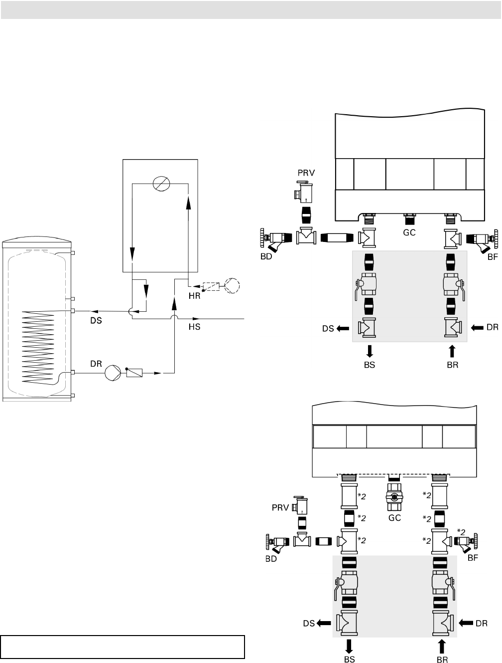
DHW Production
Domestic Hot Water Production
Vitodens 200-W boilers can be used in conjunction
with the stand-alone DHW storage tanks offered by
Viessmann. All Viessmann DHW storage tanks sold in
North America are available in “Vitosilver” finish only.
Size and select the DHW storage tank based on the
forecasted DHW consumption of the building in question.
For further technical information on DHW storage tanks,
see the Vitocell-V Technical Data Manuals.
Legend
DR Boiler heating return for domestic hot water
production
DS Boiler heating supply for domestic hot water
production
HR Heating Return
HS Heating Supply
BD Boiler Drain
BR Boiler Return
BS Boiler Supply
GC Gas Connection
PRV Pressure Relief Valve
BF Boiler Fill
PG Pressure Gage (not shown)
*1 See page 41 for alternate DHW connection.
*2 Discard when using the multi-boiler distribution
manifold
An adequately sized pre-charged expansion tank must be
used. See Installation Examples for details.
IMPORTANT
*1 DHW
Connections
(Field Supplied)
For the connection of a stand-alone DHW tank,
installation fittings (field supplied), an external circulating
pump for DHW production (field supplied) and a DHW
temperature sensor (optional equipment, see Viessmann
Price List for order information) are required.
Connections for model B2HA 100
Connections for models B2HA 112 and 150
Vitodens 200-W B2HA 100 to 150 Technical Data
*1 DHW
Connections
(Field Supplied)
5683 718 - 04
16
DHW Recirculation/ Boiler Mounting
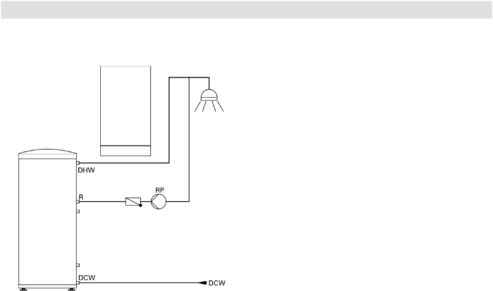
Domestic Hot Water Recirculation
DHW recirculation lines increase the level of comfort and
convenience of the domestic hot water supply and reduce
water consumption.
These advantages directly derive from the immediate
availability of domestic hot water at all draw points.
Poor insulation of the DHW recirculation line, however,
can result in considerable heat loss. Viessmann therefore
recommends that effective insulation be provided and
used for DHW recirculation lines of 23 ft. (7 m) in length
or longer.
Vitocell-V stand-alone DHW storage tank
Legend
DCW Domestic Cold Water
DHW Domestic Hot Water
TPV Temperature and Pressure Relief Valve
(on tank - not shown)
R DHW Recirculation Line
RP DHW Recirculation Pump
Vitodens 200-W B2HA 100 to 150 Technical Data
17
5683 718 - 04
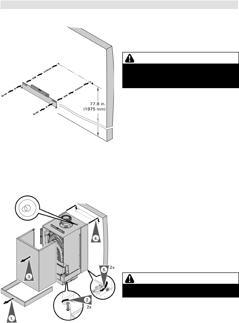
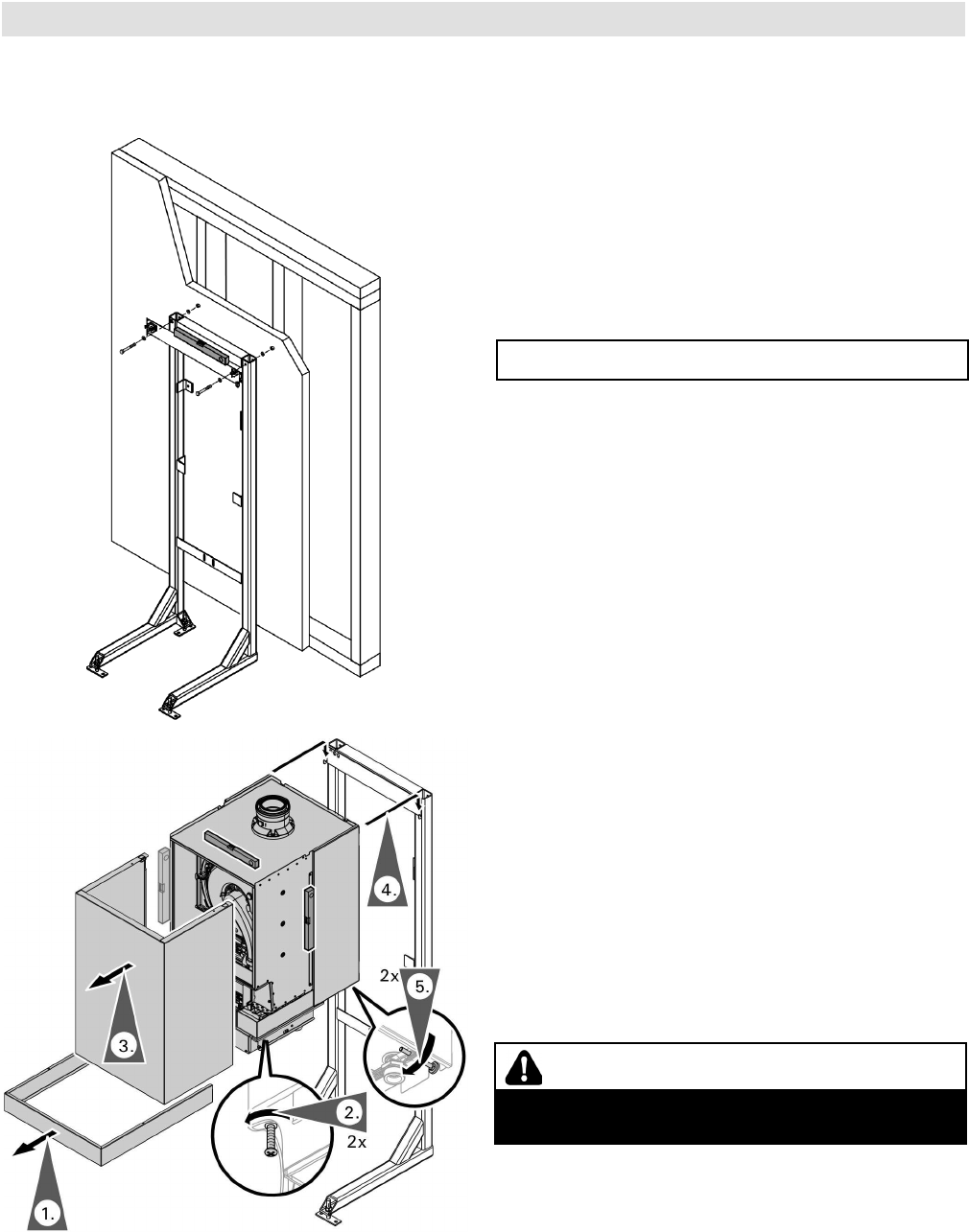
Boiler Mounting
Model B2HA 100 Wall Mount
1. Remove the external accessories connection box
cover.
2. Loosen the screws at the bottom of the boiler
(do not remove completely).
3. Remove the front encloser panel (lift up and pull
away from the boiler).
4. Mount boiler onto the mounting bracket.
5. Adjust the levelling screws to ensure the boiler
is level. Place the round bubble level on top of the
boiler to verify.
6. Connect the boiler to the installation fittings.
Vitodens 200-W B2HA 100 to 150 Technical Data
CAUTION
Whichever mounting method is used, ensure that the
bracket is tightly and securely fastened to wall. Failure
to secure boiler properly could cause boiler to loosen,
posing a severe safety hazard.
Fitting the wall mounting bracket
See the installation instructions applicable to the
mounting bracket on each type of material.
CAUTION
The boiler must be level both vertically and horizontally
to ensure proper draining of the condensate.
Vitodens 200-W B2HA 100 to 150 Technical Data
5683 718 - 04
18
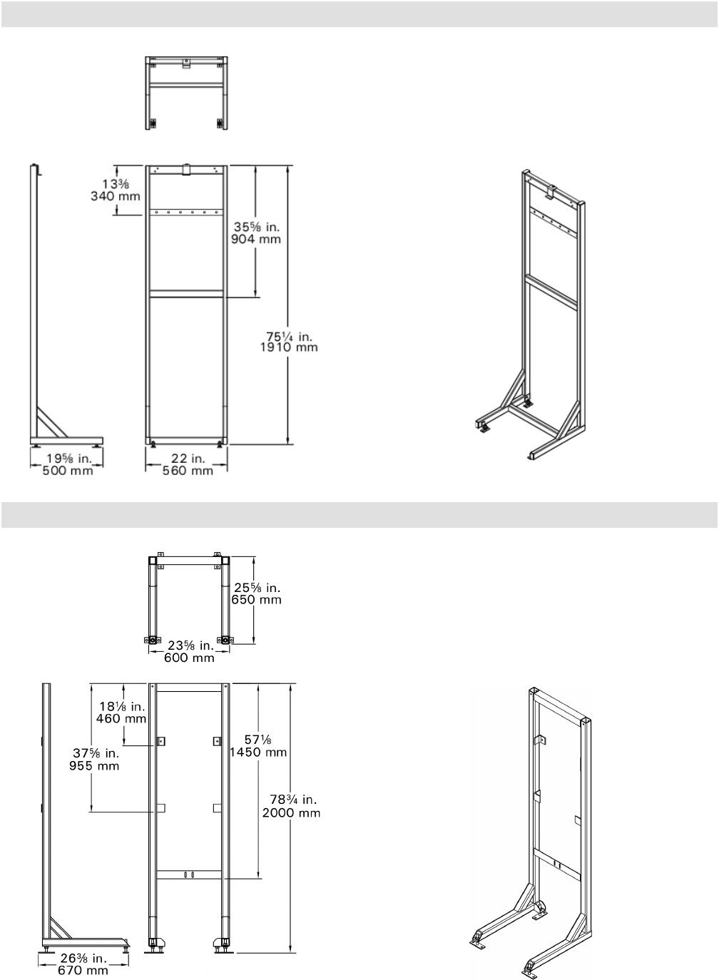
Boiler Stand for B2HA 112 and 150
The boiler stand is used for free-standing installation of a
single boiler within the mechanical room.
When using the boiler stand, ensure that the stand is
securely fastened to the floor (recommended concrete
expansion anchors are Hilti model KB-TZ e x 4 or
equivalent.
The boiler stand is used for free-standing installation of a
single boiler within the mechanical room.
When using the boiler stand, ensure that the stand is
securely fastened to the floor (recommended concrete
expansion anchors are Hilti model KB-TZ e x 4 or
equivalent.
Boiler Stand for B2HA 100
Boiler Mounting
Vitodens 200-W B2HA 100 to 150 Technical Data
19
5683 718 - 04
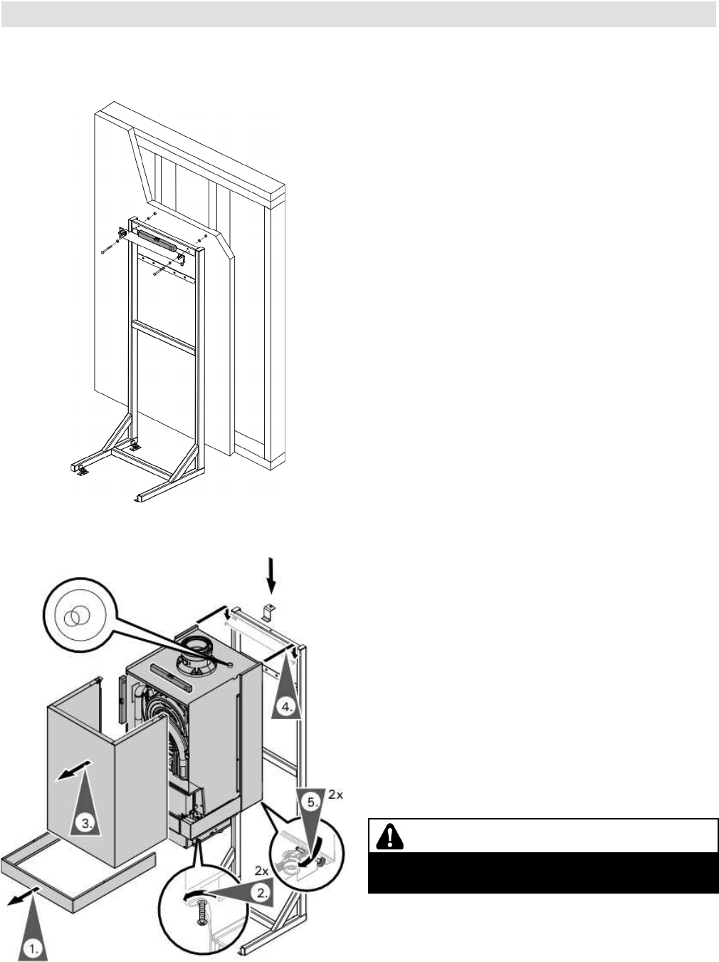
Boiler Mounting
Model B2HA 100 Stand Mount
The Vitodens 200-W, model B2HA does not come with a mounting template. The wall location for the frame, mounting
bracket and all vents must be field calculated.
Boiler mounting bracket and frame
1. Attach the wall mounting bracket (supplied with the
boiler) to the boiler mounting frame using the supplied
hardware. Ensure that the wall mounting bracket is
level.
2. Move the rack into position and secure to the floor
(and to the wall if needed).
1. Remove the external accessories connection box
cover.
2. Loosen the screws at the bottom of the boiler
(do not remove completely).
3. Remove the front encloser panel (lift up and pull
away from the boiler).
4. Mount boiler onto the mounting bracket and ensure
the boiler is securely mounted. Then install the
holding bracket to the frame on top of the boiler.
5. Adjust the levelling screws to ensure the boiler
is level.
6. Connect the boiler to the installation fittings.
CAUTION
The boiler must be level both vertically and horizontally
to ensure proper draining of the condensate.
5683 718 - 04
20
Boiler Mounting
Models B2HA 112, 150
The Vitodens 200-W, model B2HA does not come with a mounting template. The wall location for the frame, mounting
bracket and all vents must be field calculated.
Boiler mounting bracket and frame
1. Attach the wall mounting bracket (supplied with the
boiler) to the boiler mounting frame using the supplied
hardware. Ensure that the wall mounting bracket is
level.
2. Move the rack into position and secure to the floor
(and to the wall if needed).
1. Remove the external accessories connection box
cover.
2. Loosen the screws at the bottom of the boiler
(do not remove completely).
3. Remove the front encloser panel (lift up and pull
away from the boiler).
4. Mount boiler onto the mounting bracket and ensure
the boiler is securely mounted.
5. Adjust the levelling screws to ensure the boiler
is level.
6. Connect the boiler to the installation fittings.
Vitodens 200-W B2HA 100 to 150 Technical Data
CAUTION
The boiler must be level both vertically and horizontally
to ensure proper draining of the condensate.
IMPORTANT
When using the boiler restraint brackets, follow the
instructions supplied with the restaints prior to installing
the mounting bracket.
21
5683 718 - 04
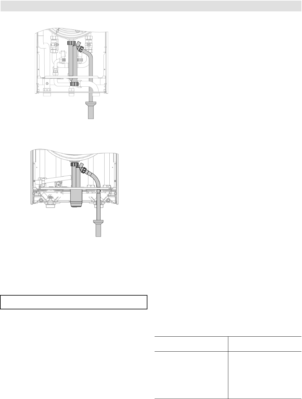
Condensate Connection/Neutralization Unit
Condensate Connection
Install the condensate drain pipe with a suitable gradient.
Discharge condensate from the boiler into the drainage
system, either directly or (if required) via a neutralization
unit (accessory).
Pipe ventilation must take place between the siphon trap
and the neutralization unit (if applicable).
Condensate Connection for Vitodens
200-W, models B2HA 100
Condensate Connection for Vitodens
200-W, models B2HA 112, 150
IMPORTANT
Condensate Drainage and Neutralization
The condensate formed both in the condensing boiler and
in the flue gas pipe must be discharged into the public
sewage system in accordance with all applicable local
regulations. The condensate produced by a gas-fired
heating system has a pH value between 3 and 4.
Some local codes may require the use of a separate
neutralization unit to treat the aggressive and corrosive
nature of the condensate. With a neutralization unit
installed, all condensate from the boiler and the flue gas
pipe enters into the neutralization unit where it is treated
and released into the public sewage system with a safe
pH value of above 6.5.
The use of neutralization granulate (performing the
neutralizing process) is dependent on the operation of the
heating system. To determine the required refill amount,
check granulate level several times during the first year
of operation. In some cases one granulate fill may last an
entire year.
Contact Viessmann to order a neutralization unit for the
Vitodens 200-W boiler.
See Viessmann Price List for order information.
The condensate discharge outlet to the drainage system
connection must be clearly visible. It must be installed
with a suitable gradient and provided with a stench trap.
If the condensate outlet of the Vitodens 200-W boiler is
lower than the drain, a condensate pump must be used.
Only corrosion-resistant materials must be used for
condensate drainage purposes (e.g. braided hose). Do not
use galvanized materials or materials containing copper for
piping, couplings etc.
The condensate drain must have a trap to prevent flue gas
leakage.
Please note that other requirements might apply
depending on local regulations and/or project-specific
details.
It is advisable to contact your local waterworks office
(authority responsible for waste water regulations)
well before commencing with the installation of the
neutralization unit in order to establish details of local
regulations that apply.
The following table shows the concentration of (effluent)
substances (e.g. heavy metals) contained in the waste
water from the Vitodens 200-W condensing boiler.
Condensate (effluent)
substances
Values measured in mg/L
Vitodens 200-W
Lead
Cadmium
Chromium
Copper
Nickel
Zinc
Tin
< 0.01
< 0.005
< 0.01
< 0.01
< 0.01
< 0.05
< 0.05
Vitodens 200-W B2HA 100 to 150 Technical Data
5683 718 - 04
22
Venting Options/Electrical Connection/Control
Venting Options
Vent Connection, models B2HA 100 Vent Connection, models B2HA 112, 150
For detailed information refer to the Installation Instructions for the Vitodens 200-W, B2HA Venting System.
Power Supply
The Vitodens 200-W requires a 120 VAC power supply
from a wall receptacle (15A fuse protected circuit).
Refer to the Installation Instructions for wiring details or
reference the “Overview of Electrical Connections” on
pages 42 and 44 of this manual.
Power Supply Connection of Accessories
The power supply connection of accessories can be made
directly at the boiler control. The connection is activated
and deactivated with the system on/off switch.
The mixing valve accessory kit and the Vitosolic control (if
used) will require a separate 120 VAC power supply from
the wall receptacle.
Electrical Connections
Wire cabling required for:
■ outdoor temperature sensor
■ Vitotronic 200-H, HK1B mixing valve control
■ accessory kit for heating circuit with mixing valve
■ Vitotrol 200 remote control
■ Vitotrol 300 remote control
■ remote switching of operating mode
■ remote disable
■ alarm output
Vitodens 200-W B2HA 100 to 150 Technical Data
23
5683 718 - 04
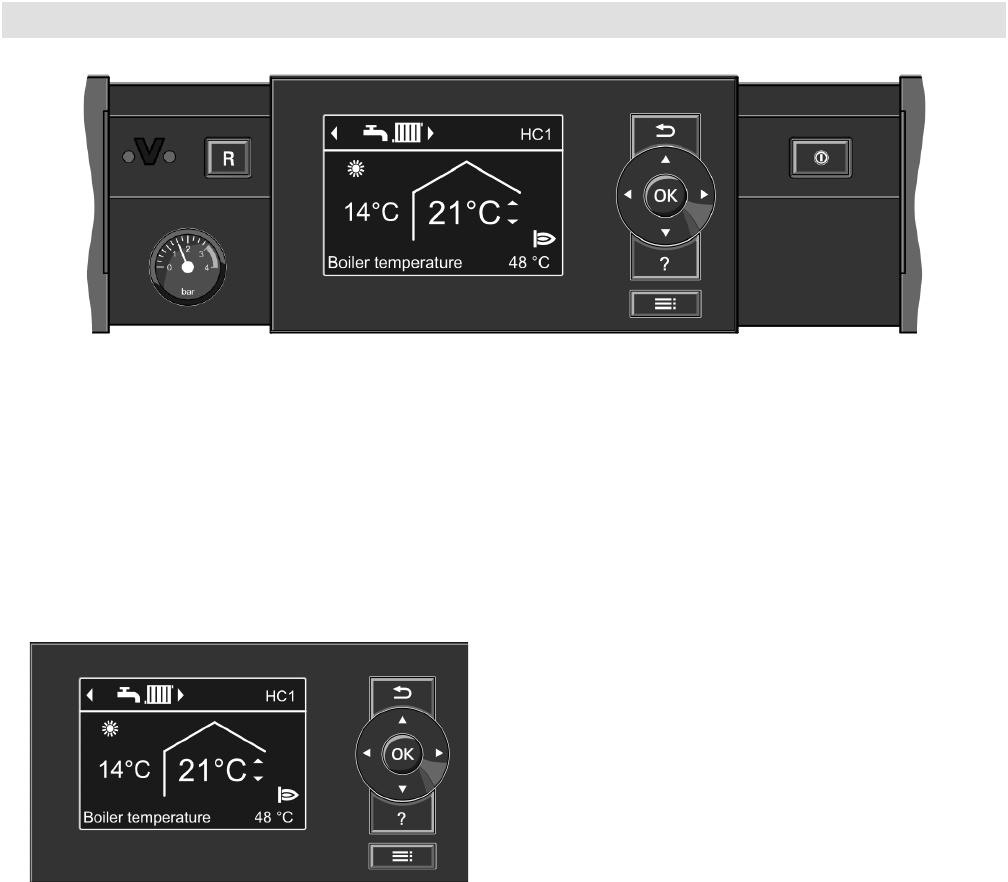
Boiler Control
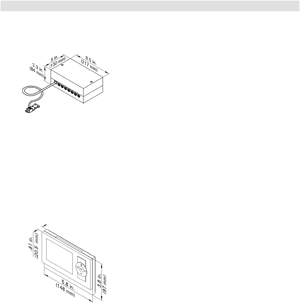
On-Board Vitotronic 200, HO1B Control
Modular structure
The control unit is integrated into the boiler. The control
unit comprises a standard unit, electronics modules and
a programming unit.
Standard unit:
■ ON/OFF switch
■ Optolink laptop interface
■ Operating and fault indicators
■ Reset button
■ Fuses
Programming unit:
■ Easy operation through:
– Plain text display with graphic ability
– Large font and black & white depiction for good
contrast
– Context-sensitive help text
– Removable programming unit; can be mounted
on the wall with separate accessory
■ With digital time switch
■ Control keys for:
– Navigation
– Confirmation
– Help and additional information
– Menu
■ Setting the:
– Room temperature
– Reduced room temperature
– DHW temperature
– Heating program
– Time programs for central heating, DHW heating
and DHW circulation
– Economy mode
– Party mode
– Holiday program
– Heating curves
– Codes
– Actuator tests
– Test mode
■ Displaying the:
– Boiler water temperature
– DHW temperature
– Operating details
– Diagnostic details
– Fault messages
Vitodens 200-W B2HA 100 to 150 Technical Data

5683 718 - 04
24
Boiler Control
Design and Function
Functions
■ Weather-compensated control of the boiler water
and/or flow temperature
■ Control of one heating circuit without mixer and two
heating circuits with mixer
■ Electronic maximum and minimum temperature limit
■ Demand-dependent heating circuit pump and burner
off control
■ Adjustment of a variable heating limit
■ Anti-seizing pump protection
■ Heating system frost protection
■ Integral diagnostic system
■ Maintenance display
■ Cylinder thermostat with priority
■ Control of solar DHW heating and central heating
backup in conjunction with the solar control module,
type SM1
■ Display of the solar energy yield
■ Auxiliary function for DHW heating (short-term
heating to a higher temperature)
■ Slab curing program
■ External starting and blocking (in conjunction with
extension EA1)
The requirements of DIN EN 12831 for calculating the
heat load are met. To reduce the heat-up output, the
reduced room temperature will be raised in case of low
outside temperatures. The flow temperature will be raised
for a limited time to reduce the heat-up time after a
setback phase.
According to the Energy Saving Ordinance [Germany], the
temperature in each room must be individually controlled,
e.g. through thermostatic radiator valves.
Control characteristics
PI characteristics with modulating output.
Time switch
Digital time switch (integrated into the programming unit)
■ Individual day and seven-day program
■ Automatic summer/wintertime changeover
■ Automatic function for DHW heating and DHW
circulation pump
■ Time, day and standard switching times for central
heating, DHW heating and the DHW circulation pump
are factory-set
■ Switching times are individually programmable,
i.e. up to four switching periods per day
Shortest switching interval: 10 minutes
Power reserve: 14 days
Setting the operating programs
The heating system frost protection (see frost protection
function) applies to all heating programs.
The following heating programs can be selected:
■ Heating and DHW
■ Only DHW
■ Standby mode
External heating program changeover in conjunction
with EA1 extension.
Frost protection function
■ The frost protection function will be started when the
outside temperature drops below approx. 34° F (1° C).
With the frost protection function, the heating circuit
pump will be switched ON and the boiler water is
maintained at a lower temperature of approximately
68° F (20° C). The DHW tank will be heated to
approximately 68° F (20° C).
■ The frost protection function will be stopped when
the outside temperature rises above approximately
37° F (3° C) (default settings).
Summer Operation
Heating program “w”
The burner is only activated upon a call for domestic hot
water from the DHW storage tank (controlled by DHW
tank temperature sensor).
Vitodens 200-W B2HA 100 to 150 Technical Data
25
5683 718 - 04
Boiler Control
Design and Function (continued)
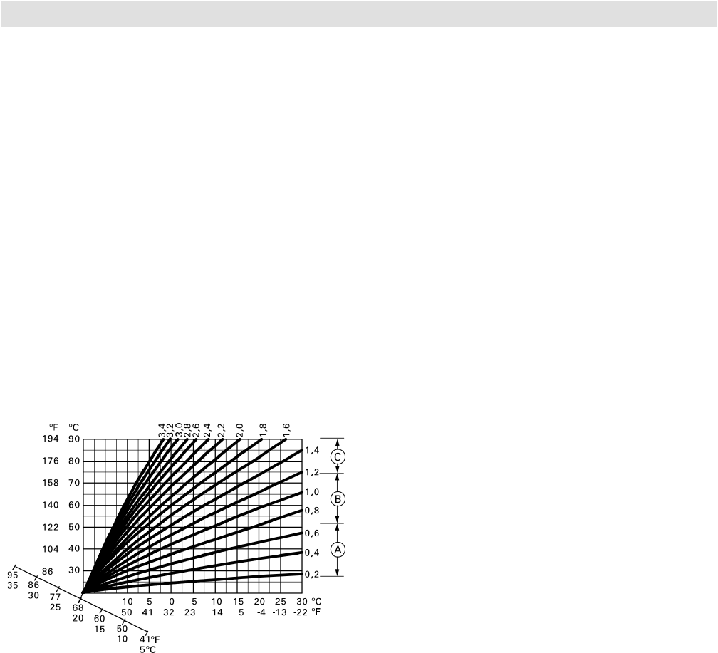
Heating Curve Adjustment (slope and shift)
The control unit regulates the boiler water temperature
(= supply temperature of heating circuit without mixing
valve) and the supply temperature of the heating circuit
with mixing valve (in conjunction with the accessory kit
for a heating circuit with mixing valve) according to the
outdoor temperature. The boiler water temperature is
automatically raised by 0 to 72 F / 0 to 40 K higher
than the currently required set supply temperature
(in the factory default setting the differential temperature
is 14.4 F / 8 K). See Start-up/Service Instructions for
coding address “9F” in coding level 2.
The supply temperature that is required to achieve a
given room temperature depends on the heating system
and the thermal insulation of the building that is being
heated.
The adjustment of the two heating curves is used to
match the boiler water temperature and the supply
temperature to these conditions. The boiler water
temperature is limited upwards by the fixed high limit
and the temperature set for the electronic high limit.
The supply temperature cannot rise above the boiler
water temperature.
Technical Data
Rated supply voltage: 120 VAC
Rated frequency: 60 Hz
Rated current: 12A
Safety category I
Max. ambient temp.
- during operation: 32 to 104º F (0 to 40º C)
Installation in living space
or boiler rooms (standard
ambient conditions)
- during storing
or transporting: -4 to +149º F (-20 to +65º C)
Electronic temperature
controller setting
(heating mode) 180º F (82° C)
(can not be changed)
Setting range for the
DHW temperature 50 to 154º F (10 to 68° C)
Legend
A Low temperature heating system,
e.g. radiant floor heating
B Medium temperature heating system,
e.g. cast iron radiation, staple-up radiant floor heating
C High temperature heating system,
e.g. fintube radiation, fan coils
Heating curve setting
- Heating curve slope: 0.2 to 3.5
- Heating curve shift: -13 to 40 K
Vitodens 200-W B2HA 100 to 150 Technical Data
Boiler water or supply
temperature
Room
set-point
temperature Outdoor temperature
5683 718 - 04
26
Boiler Temperature Sensor
The boiler temperature sensor is connected at the control
unit for weather-responsive operation and is built into the
boiler.
Max. ambient temp.
- at operation: 32 to 266º F (0 to 130º C)
- when storing
or transporting: - 4 to+158º F (-20 to+70º C)
Boiler Control
Design and Functions (continued)
Outdoor Temperature Sensor
Sensor location:
- North or northwest wall of building
- 6.6 to 8.2 ft. (2 to 2.5 m) above ground or in case
of a multi-storey building approximately halfway up
the second floor
Electrical connection:
- 2-wire cable, max. cable length 115 ft. (35 m) with
a wire size of min. AWG 16 copper
- Cable to the outdoor sensor must not be laid near
line voltage wiring (120/240 V)
Max. ambient temp.
- at operation: 32 to 194º F (0 to 90º C)
- when storing
or transporting: -40 to+158º F (-40 to+70º C)
DHW Tank Temperature Sensor
Supplied with:
- Cable length approximately 13 ft. (3.75 m),
ready to plug in
- All pipe connections are field supplied.
Specification:
Max. ambient temp.
- at operation: 32 to 194º F (0 to 90º C)
- when storing
or transporting: - 4 to+158º F (-20 to+70º C)
Vitodens 200-W B2HA 100 to 150 Technical Data
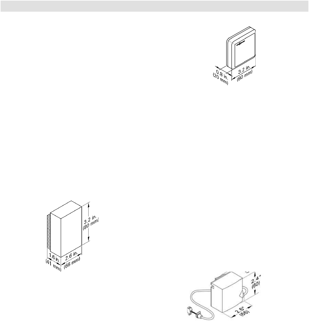
Room Temperature Sensor
Separate room temperature sensor as supplement to the
Vitotrol 200A and 300A; to be used if the Vitotrol 200A
or 300A cannot be installed inside the main living room
or in a suitable position where the unit can capture and
adjust the temperature.
Installation in the main living room on an internal wall
opposite radiators. Never install inside shelf units,
recesses, immediately by a door or heat source (e.g.
direct sunlight, fireplace, TV set, etc.).
Connect the room temperature sensor to the Vitotrol
200A or 300A.
Electrical connection:
- 2-wire cable with a wire size of min. AWG 18 copper
- The cable length between the control unit, remote
control unit and room temperature sensor must not
exceed 98 ft. (30 m)
Max. ambient temperature
- at operation: 32 to 104º F (0 to 40º C)
- when storing
or transporting: -4 to+149º F (-20 to +65º C)
Supply Temperature Sensor
(strap-on sensor, included with mixing valve actuator
accessory kit),
Installed with a strapping band.
Cable length 19.7 ft. (6 m), ready to plug in.
Max. ambient temperature
- at operation: 32 to 212º F (0 to 100º C)
- when storing
or transporting: -4 to+149º F (-20 to+70º C)
27
5683 718 - 04
Control Accessories
Vitotronic Control Accessories
Mixing Valve Extension Module
Rated voltage: 120 VAC
Rated frequency: 60 Hz
Rated current: 4 (2) A
Power consumption: 4 W
Max. ambient temp.
- at operation: 32 to 104º F (0 to 40º C)
- when storing
or transporting: -4 to+149º F (-20 to+65º C)
- Relay output for
heating circuit pump: 4 (2) A, 120 VAC
- Actuator torque: 3 Nm
- Time of 90º: 2 minutes
Mixing Valve Actuator Kit
The mixing valve actuator is mounted directly on the
Viessmann ¾ to 2½” mixing valve.
The mixing valve actuator is a motor-driven control unit.
The rotational direction is reversible.
The mixing valve actuator comes with a plug-in connector
for a heating circuit pump, supply temperature sensor
(strap-on sensor with 7 ft. (2.1 m) connecting cable),
power supply connecting cable 9 ft. (2.7 m) and a
connecting cable 9 ft. (2.7 m) for the KM-BUS Expansion
Module.
Rated voltage: 120 VAC
Rated frequency: 60 Hz
Rated current: 4 A
Power consumption: 5W max. ambient temperature
- at operation: 32º F to 104º F (0º C to 40º C)
application in living areas and installation sites
(normal ambient conditions)
-storage & shipping: -4º F to 149º F (-20º C to 65º C)
Max. relay outputs at 120 VAC for:
- Heating circuit pump: 1.0 A
- Mixing valve: 0.2 A
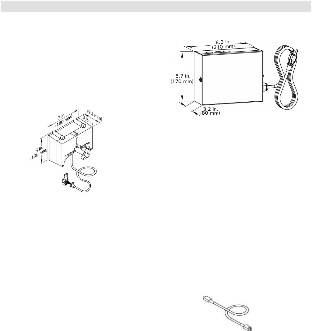
LON Communication Module
Electronic PCB for data exchange with the Vitotronic
200-H, Vitocom 200 and for connecting to a higher level
building management system.
LON Connecting Cable
(for data exchange between control units)
Cable length 23 ft. (7 m), fully wired
LON Terminal End Resistor
To terminate the LON BUS at the first and the last control
unit.
Vitodens 200-W B2HA 100 to 150 Technical Data
Immersion Temperature Sensor
To capture the low loss temperature
Specification
Lead length fully wired: 12 ft. (3.75 m),
Permissable ambient temp.
- during operation: 32 to 194° F (0 to 90° C)
- during storage and
transport: - 4 to+158° F (-20 to+70° C)
5683 718 - 04
28
Control Accessories
Vitotronic Control Accessories (continued)
KM BUS Expansion Module
To connect 2 to 9 devices (mixing valve actuator, Vitotrol,
input module, etc.) to the single KM BUS connection of
the boiler.
Specification
Lead length: 10 ft. (3.0 m), fully wired
Max. ambient temp.
- at operation: 32 to 104º F (0 to 40º C)
- when storing
or transporting: -4 to+149º F (-20 to+65º C)
Vitotrol 200A (continued)
WS function:
Installation anywhere in the building.
RS function:
Note: Never activate the RS function for underfloor
heating circuits (inertia). In heating systems with
a heating circuit without mixing valve and heating
circuits with mixing valve, the RS function must
only affect the heating circuit with mixing valve.
Room temperature hook-up:
Installation in the main living room on an internal wall
opposite radiators. Never install inside shelf units,
recesses, immediately by a door or heat source (e.g.
direct sunlight, fireplace, TV set, etc.).
The integral room temperature sensor captures the actual
room temperature and effects any necessary corrections
of the supply temperature as well as a rapid heat-up
at the start of the heating operation (if appropriately
programmed).
Connection:
- 2-core lead, length max. 50 m (even if connecting
several remote control units)
- Never route this lead immediately next to 120/208/460 V
cables
- LV plug as standard delivery
Specification:
Power supply via KM BUS
Power consumption 0.2 W
Protection class III
Max. ambient temp.
- at operation: 32 to 104º F (0 to 40º C)
- when storing
or transporting: -4 to+149º F (-20 to+65º C)
Set room temp. range: 37 to 99º F (3 to 37º C)
The set room temperature for reduced mode is adjusted
at the control unit.
Vitotrol 200A
One Vitotrol 200A can be used for every heating circuit
in a heating system. The Vitotrol 200A can regulate one
heating circuit and up to two remote controls may be
connected to the control unit.
Vitodens 200-W B2HA 100 to 150 Technical Data
KM BUS Participant
The Vitotrol 200A remote control regulates the required
set room temperature in standard mode, from any room
in the house.
- Party and economy mode can be enabled via keys
- Only for heating circuit with mixing valve
Fitted room temperature sensor for room temperature
hook-up
29
5683 718 - 04
Control Accessories
Vitotronic Control Accessories (continued)
Vitotrol 300A
One Vitotrol 300A can be used for every heating circuit
in a heating system. The Vitotrol 300A can regulate up
to three heating circuits. Up to two remote controls may
be connected to the control unit.
KM BUS Participant
The Vitotrol 300A remote control regulates the required
set room temperature for one heating circuit in standard
and reduced mode, the heating program and the switching
times for central heating, DHW heating and the DHW
circulation pump.
Displaying:
- Room temperature
- Outside temperature
- Heating program
- Operating condition
- Solar yield as graphic display
Settings:
- Set room temperatures for standard mode
(day temperature) and reduced mode (night temperature)
via the standard display
- Heating program, switching times for heating circuits,
DHW heating and DHW circulation pump plus further
settings via plain text menu on the display
- Party and economy mode can be enabled via the menu
- Only for heating circuit with mixer:
Fitted room temperature sensor for room temperature
hook-up
Note: For room temperature hook-up, the Vitotrol 300A
must be installed in the main living room (lead room).
WS function:
Installation anywhere in the building.
RS function:
Installation in the main living room on an internal wall
opposite radiators. Never install inside shelving units,
in recesses, or immediately by a door or heat source
(e.g. direct sunlight, fireplace, TV set, etc.). The fitted
room temperature sensor captures the actual room
temperature and effects any necessary correction of
the flow temperature.
Vitotrol 300A (continued)
Connection:
- 2-core lead, length max. 164 ft. (50 m) (even if
connecting several remote control units)
- Never route this lead immediately next to 120/208/460 V
cables
- LV plug as standard delivery must be installed in the main
living room (lead room).
Specification:
Power supply via KM BUS
Power consumption 0.2 W
Protection class III
Max. ambient temp.
- at operation: 32 to 104º F (0 to 40º C)
- when storing
or transporting: -4 to+149º F (-20 to+65º C)
Set room temp. range 37 to 99º F (3 to 37º C)
The set room temperature for reduced mode is adjusted
at the control unit.
Vitodens 200-W B2HA 100 to 150 Technical Data
5683 718 - 04
30
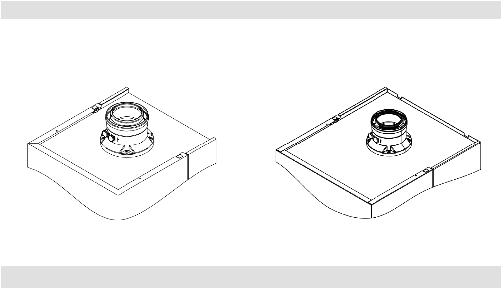
Accessories
Accessories for Vitodens 200-W
Neutralization Unit for Single-Boiler Applications
with neutralizing granulate
for models B2HA 100, 112, 150
Neutralization Pellets
for models B2HA 100, 112 and 150
8 kg for refill or replacement purposes
Fuel Conversion Label Kit (NG>LPG)
(included in boiler technical literature set)
The Vitodens 200-W, B2HA boiler comes factory set
for operation with natural gas. All B2HA models can be
field converted to operate with liquid propane gas (as
well as back to natural gas as required). The kit includes
instructions and labels for field conversion.
Low-Loss Header
When used in conjunction with the Vitodens 200-W
boiler, the low-loss header acts as hydraulic break,
decoupling boiler and system circuits from each other.
It is recommended to use the low-loss header in
applications in which the total system flow rate exceeds
the maximum (or minimum) boiler flow rate.
For maximum boiler flow rates, see page 9 of this manual.
Viessmann strongly recommends the use of a low-loss
header in cases where the system head and flow rates
are unknown.
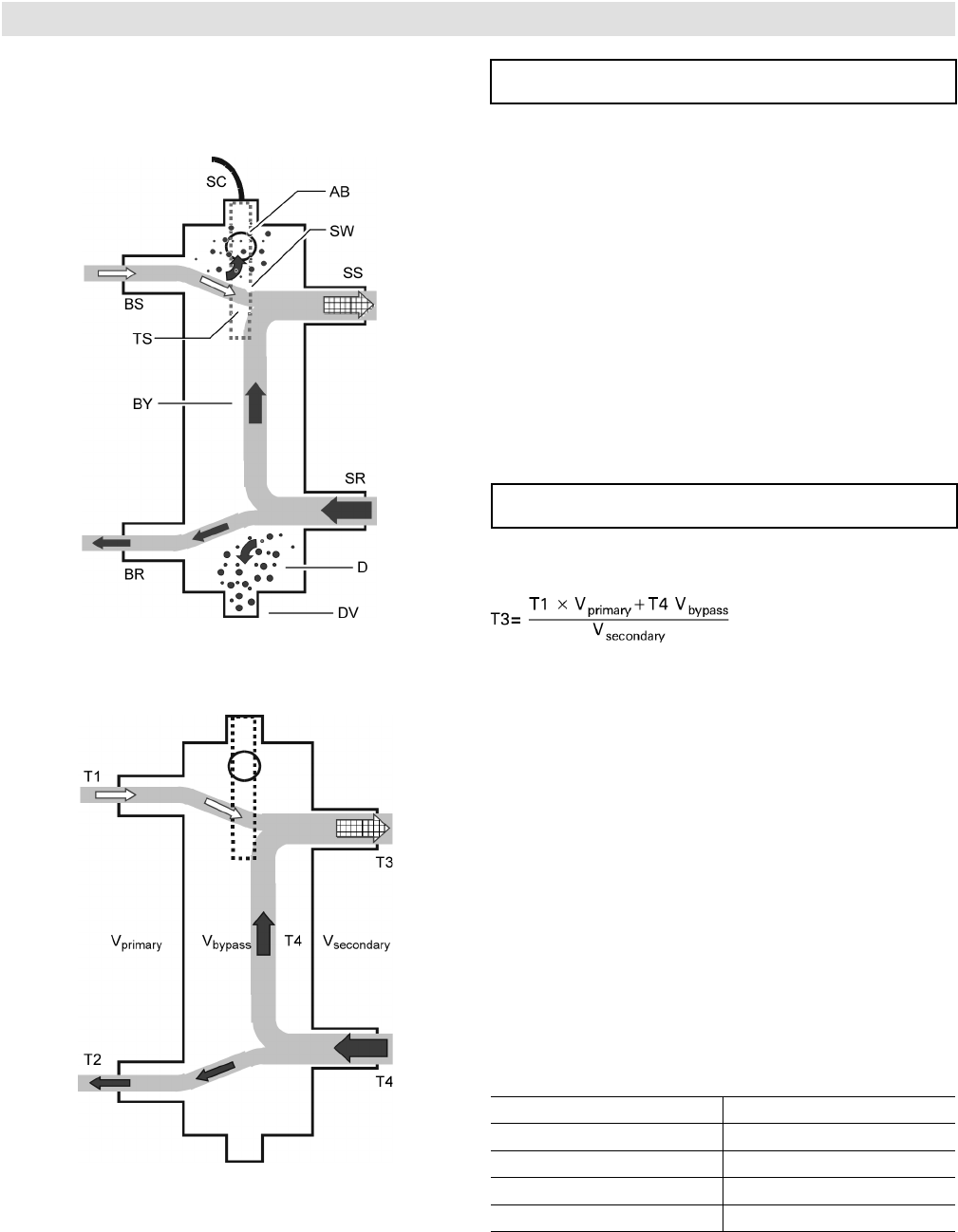
The temperature sensor connection [TS] typically located
at the top of the low-loss header ensures low return
temperatures to the Vitodens 200-W boiler at all times,
increasing operational efficiency.
In addition, the low-loss header helps eliminate air and
debris [D] from the heating system.
See illustrations for design and principle of operation.
The low-loss header is available in the following sizes.
Select the size based on the maximum system flow rate
of your application.
Vitodens 200-W B2HA 100 to 150 Technical Data
31
5683 718 - 04
Accessories
Accessories for Vitodens 200-W
Low-Loss Header (continued)
Use only a Viessmann supplied temperature sensor. Do
not use any other manufacturer’s temperature sensor.
Legend
AB Air Bleed
BR Boiler Return
BS Boiler Supply
BY Bypass (with laminar flow)
D Debris and/or air
DV Drain Valve
SC Sensor Cable
SR System Return
SS System Supply
TS Viessmann Temperature Sensor
SW Sensor Well
When installing a low-loss header, the system mixed
supply temperature (T3) must be calculated as follows:
Legend
T1 Boiler supply temperature
T2 Boiler return temperature
T3 System supply temperature
T4 System return temperature
Vprimary Boiler circuit flow rate
Vsecondary Heating circuit flow rate
Vbypass Bypass flow rate
Qprimary Heat supplied by boiler
Qsecondary Heat consumed by system
Vprimary < Vsecondary
T1 > T3
T2 = T4
Qprimary = Qsecondary
T1 167° F (75° C)
Vsecondary=Vprimary+Vbypass
IMPORTANT
IMPORTANT
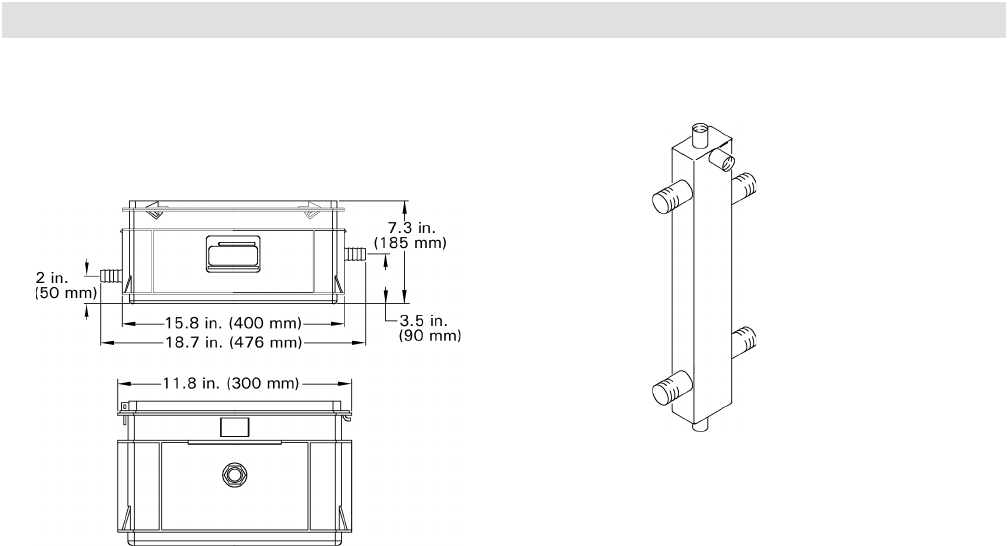
Model No. Max. system flow rate
Type 80/60 17.6 GPM / 4 m3/h
Type 120/80 35.2 GPM / 8 m3/h
Type 160/80 *1 44 GPM / 10 m3/h
Type 200/120 *180 GPM / 18 m3/h
*1 Floor-mounted version (typically used for
multiple-boiler installations).
Low-loss header design (Type 80/50 or 120/80)
Principle of Operation
Vitodens 200-W B2HA 100 to 150 Technical Data

5683 718 - 04
32
Standard Equipment/Management System
Standard Equipment
Combustion Management System
The Vitodens 200-W gas-fired condensing boiler with
Inox-Radial heat exchanger, modulating MatriX cylinder
burner for liquid propane gas and natural gas (available
on all models), comes standard with:
■ pressure gage
■ installation fittings with 30 psig pressure
relief valve
■ boiler control unit with outdoor
temperature sensor, power/pump module
- The boiler comes pre-wired and fully piped
internally for field connections and pre-wired.
- Venting material (coaxial) is to be supplied by
others. Side wall vent installations must include
a protective screen!
- Enclosure finish:
black steel, powder-coated white
- The Vitodens 200-W comes ready for use
with natural gas and can be fuel
converted to liquid propane gas in the field.
- Power/Pump module
Wall mounting componentry
The following wall mounting components are supplied
with the Vitodens 200-W boiler:
■ Mounting bracket
■ Mounting bolts
■ Installation fittings
■ Screws for mounting bracket on
- wood studs (2” x 4”)
- metal studs
- brick/concrete wall
The combustion management system utilizes the physical
correlation between the level of the ionization current
and the air factor λ. For all gas qualities, the maximum
ionization current results with air factor λ.
The ionization signal is evaluated by the combustion
management system, and the air factor is adjusted to
between λ=1.24 and 1.44. This range provides for an
optimum combustion quality. Thereafter, the electronic
gas valve regulates the required gas volume based on the
prevailing gas quality.
To check the combustion quality, the CO2 content or the
O2 content of the flue gas is measured. The actual values
enable the prevailing air factor to be determined.
The relationship between the CO2 or O2 content and
air factor λ is illustrated in the table below.
To achieve an optimum combustion control, the system
regularly performs an automatic self-calibration; also after
a power failure (shutdown). For this, the combustion is
briefly regulated to max. ionization current (equals air factor
λ=1). The automatic calibration is performed shortly after
the burner starts and lasts approximately 5 seconds.
During the calibration, higher than normal CO emissions
may occur briefly.
The combustion management system can also be
calibrated manually, e.g. after maintenance or service
work (coding address “85”, see Service Instructions).
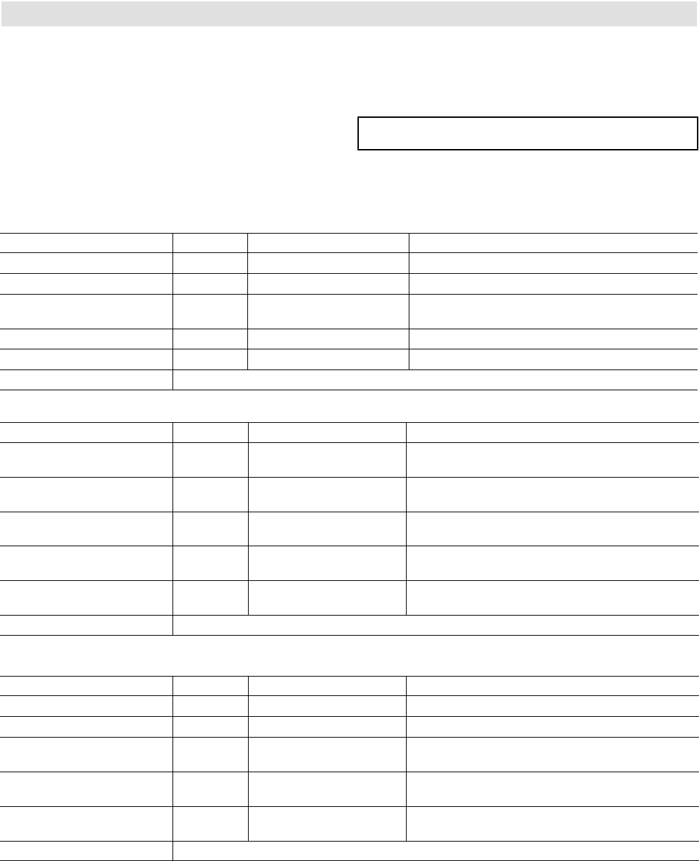
The Vitodens 200-W, B2HA boilers come equipped with Lambda Pro, the industry’s first intelligent combustion
management system.
Air factor λ - CO2/O2 content
Air factor λO2 content (%) CO2 content (%) for natural gas CO2 content (%) for liquid propane gas
1.20 3.8 9.6 11.3
1.24 4.4 9.2 10.9
1.27 4.9 9.0 10.6
1.30 5.3 8.7 10.3
1.34 5.7 8.5 10.0
1.37 6.1 8.3 9.8
1.40 6.5 8.1 9.6
1.44 6.9 7.8 9.3
1.48 7.3 7.6 9.0
Vitodens 200-W B2HA 100 to 150 Technical Data
33
5683 718 - 04
Installation
Installation Examples
Please note that in the following piping layout examples, all pumps are field supplied.
IMPORTANT IMPORTANT
The examples on the following pages depict possible
piping layouts of the Vitodens 200-W boiler equipped with
Viessmann System Technology.
For boiler and tank combinations, please install only
feasible combinations listed in the Viessmann Price List.
Please note that the following examples are simplified
conceptual drawings only!
Piping and necessary componentry must be field verified.
A low water cut-off (LWCO) must be installed where
required by local codes.
Proper installation and functionality in the field is the
responsibility of the heating contractor.
DHW supply and return piping between boiler DHW
connections and the Viessmann DHW tank connections,
shall be a minimum of 1¼” (for models B2HA 45 to 100)
and 2 in. (for models B2HA 112 to 150) DHW connection
outlet sizes provided on the boiler and the DHW tank).
This will ensure the residual head of the field supplied
pump is fully utilized to overcome the resistance of the
DHW heat exchanger coil and to provide sufficient water
flow to the boiler heat exchanger.
In non-Viessmann DHW tank applications, perform, in
addition to the above, accurate calculations for DHW
tank coil pressure drop versus boiler pump (field supplied)
residual head to ensure sufficient water flow to the boiler
heat exchanger. Failure to heed the above instructions
may cause boiler short-cycling and inadequate DHW
supply.
WARNING
If a DHW storage tank other than a Viessmann
Vitocell 100 or 300 tank is used, the installer must
verify proper operation of the Viessmann DHW tank
temperature sensor with the original manufacturer
of the tank. Viessmann strongly recommends the
installation of a temperature tempering valve in the
DHW supply line.
Hydraulic Connection
System design
Viessmann condensing boilers can generally be installed
in any pumped hot water heating system (closed system).
The circulation pump is an integral part of the appliance.
Minimum system pressure 15 psi (1.0 bar).
The boiler water temperature is limited to 180º F (82º C).
To minimise distribution losses, we recommend that
you size the heat distribution system to a max. flow
temperature of 158º F (70º C).
For apartments with less than 860 ft2 (80 m2) living
space or for low energy houses with low heat demand
we recommend, due to the immediate capturing of the
room-influencing factors, the utilisation of the Vitodens
with a constant temperature control unit in conjunction
with the Vitotrol 100.
To reduce burner cycling in low energy houses with a
correspondingly low heat demand, we recommend the
use of a low loss header.
Vitodens 200-W B2HA 100 to 150 Technical Data

5683 718 - 04
Installation Examples
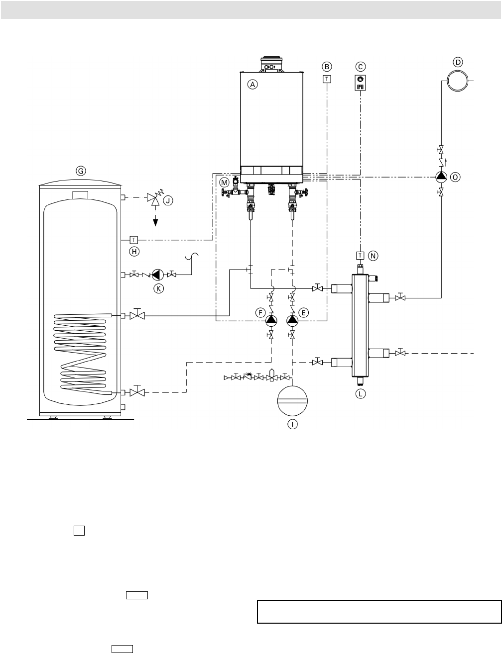
System Layout 1
Vitodens 200-W B2HA 100 to 150 Technical Data
Vitodens 200-W, B2HA with a direct-connected heating circuit
Installation of ...
■ radiator heating circuit (high-temp. circuit)
■ DHW production
... with the following flow conditions:
The flow rate of the heating circuit is less than the
maximum possible water flow rate of the Vitodens 200-W
B2HA boiler (see page 9 for maximum water flow rate of
boiler).
The use of a low-loss header is strongly recommended if
the maximum water flow rate in the application concerned
exceeds the values shown in the applicable table on page
10, or if the system flow rates are unknown.
The low-loss header is available as accessory part.
See following pages for installation examples with a low-
loss header.
DHW circulating pump F must pump into the Vitodens
200-W boiler (as illustrated).
IMPORTANT
34
Legend
A Vitodens 200-W B2HA boiler with
Vitotronic 200, HO1B outdoor reset control
B Outdoor temperature sensor !
C Vitotrol remote (optional)
D Heating circuit
E Heating circuit pump 20
F DHW circulating pump sA
G DHW storage tank
H DHW tank temperature sensor %
I Expansion tank
J Flow check valve
K DHW recirculation pump *
L Temperature and pressure relief valve
M Pressure relief valve
* Function based on coding of address 33
28/20
5683 718 - 04
35
Vitodens 200-W B2HA 100 to 150 Technical Data Installation Examples
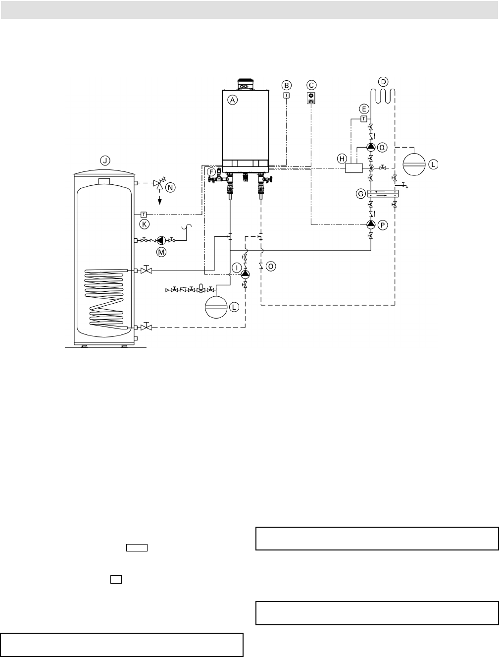
System Layout 2
Vitodens 200-W, B2HA with one heating circuit and low-loss header
Installation of ...
■ radiator heating circuit (high-temp. circuit)
■ DHW production
... with the following flow conditions:
The flow rate of the heating circuit is greater than the
maximum possible water flow rate of the Vitodens
200-W B2HA boiler (see page 9 for maximum water flow
rate of boiler).
The use of a low-loss header is strongly recommended
if the maximum water flow rate in the application
concerned exceeds the values shown on page 10,
or if the system flow rates are unknown.
The low-loss header is available as accessory part.
Please note location of expansion tank.
DHW circulating pump F must pump into the Vitodens
200-W B2HA boiler (as illustrated).
IMPORTANT
Legend
A Vitodens 200-W B2HA boiler with
Vitotronic 200, HO1B outdoor reset
control
B Outdoor temperature sensor !
C Vitotrol remote (optional)
D Heating circuit
E Boiler pump 20
F DHW circulating pump sA
G DHW storage tank
H DHW tank temperature sensor %
I Expansion tank
J Temperature and pressure relief valve
K DHW recirculation pump 28/20 *
L Low-loss header
M Pressure relief valve
N Viessmann temperature sensor for
low-loss header ?
O Heating circuit pump 28/20 *
* Function based on coding of address 33
5683 718 - 04
Vitodens 200-W B2HA 100 to 150 Technical Data
Installation Examples
System Layout 3
36
Vitodens 200-W, B2HA with...
- DHW storage tank
- one heating circuit with mixing valve and system separation
Installation of ...
■ underfloor heating circuit with 3-way mixing valve
and system separation (low-temp. circuit)
■ DHW production
... with the following flow conditions:
The flow rate of the heating circuit is less than the
maximum possible water flow rate of the Vitodens
200-W B2HA boiler.
See page 30 for maximum water flow rate of the Vitodens
200-W B2HA boilers. The use of a low-loss header is
recommended if the system water flow rate is unknown.
The low-loss header is available as accessory part.
See following pages for installation examples with a
low-loss header.
System separation is required of underfloor heating
systems employing non-oxygen diffusion barrier tubing.
All components on the secondary side of the heat
exchanger must be made of corrosion-resistant materials.
Sizing of field-supplied pump P is critical for proper boiler
operation in this system layout. See page 9 for the supply
head pressure drop of the boiler. An undersized pump
may cause short-cycling and/or improper operation of the
boiler. Viessmann STRONGLY recommends using a low-
loss header and a boiler pump in this system layout.
IMPORTANT
IMPORTANT
IMPORTANT
Legend
A Vitodens 200-W B2HA boiler with
Vitotronic 200, HO1B outdoor reset
control
B Outdoor temperature !
C Vitotrol remote (optional)
D Underfloor heating circuit
E Mixing valve temperature sensor ?
F Pressure relief valve
G Plate heat exchanger for system
separation
H Accessory kit for heating circuit with
mixing valve
I DHW circulating pump sA
J DHW storage tank
K DHW tank temperature sensor %
L Expansion tank
M DHW recirculation pump 28/20 *
N Temperature and pressure relief valve
O Flow check valve
P Heating circuit pump 20
Q Heating circuit pump
* Function based on coding of address 33
DHW circulating pump must pump I into the Vitodens
200-W B2HA boiler (as illustrated).
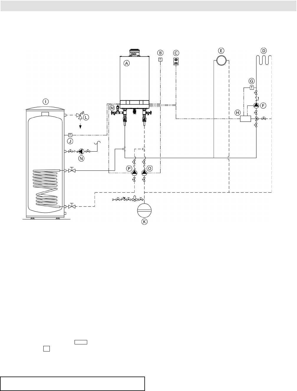
5683 718 - 04
Vitodens 200-W B2HA 100 to 150 Technical Data
37
Installation Examples
System Layout 4
Vitodens 200-W, B2HA with...
- DHW storage tank
- one direct-connected heating circuit
- one heating circuit with a mixing valve
Installation of different heating circuits...
■ radiator heating circuit (high-temp. circuit)
■ under floor heating circuit with 3-way mixing valve
(low-temp. circuit)
■ DHW production
... with the following flow conditions:
1. The water flow rate (output) of the radiator heating
circuit is at least 30% greater than that of the under
floor heating circuit.
2. The total flow rate of the two heating circuits is
less than the maximum possible water flow rate of
the Vitodens 200-W B2HA boiler (see page 9 for
max. water flow rate).
The use of a low-loss header is strongly
recommended if the maximum water flow rate in the
application concerned exceeds the values shown on
page 10, or if the system flow rates are unknown.
The low-loss header is available as accessory part.
See following pages for additional installation examples
with a low-loss header.
The 3-way mixing valve, built-in to achieve the low-
temperature level of the under floor heating circuit, is
controlled by an accessory kit for a heating circuit with
mixing valve.
IMPORTANT
Legend
A Vitodens 200-W B2HA boiler with
Vitotronic 200, HO1B outdoor reset
control
B Outdoor temperature sensor !
C Vitotrol remote (optional)
D Under floor heating circuit
E Radiator heating circuit
F Heating circuit pump
G Mixing valve temperature sensor ?
H Accessory kit for heating circuit with mixing valve
I Domestic hot water storage tank
J DHW tank temperature sensor %
K Expansion tank
L Temperature and pressure relief valve
M Pressure relief valve
N DHW recirculation pump 28/20 *
O Boiler pump 20
P DHW circulating pump sA
* Function based on coding of address 33
DHW circulating pump P must pump into the Vitodens
200-W B2HA boiler (as illustrated).
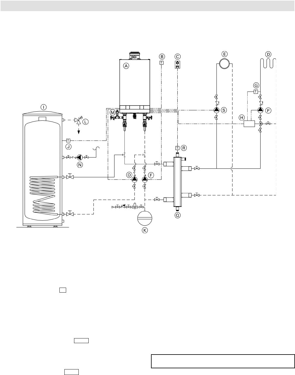
Vitodens 200-W B2HA 100 to 150 Technical Data
5683 718 - 04
Installation Examples
System Layout 5
Vitodens 200-W, B2HA with...
- DHW storage tank
- one heating circuit with mixing valve
- one heating circuit without mixing valve and low-loss header
Installation of different heating circuits...
■ radiator heating circuit (high-temp. circuit)
■ under floor heating circuit with 3-way mixing valve
(low-temp. circuit)
■ DHW production
... with the following flow conditions:
The total flow rate of the two heating circuits is greater
than the maximum possible water flow rate of the
Vitodens 200-W B2HA boiler (see page 9 for maximum
water flow rate of boiler).
The use of a low-loss header is strongly recommended.
The low-loss header is available as accessory part.
The 3-way mixing valve, built-in to achieve the low-
temperature level of the under floor heating circuit, is
controlled by an accessory kit for a heating circuit with
mixing valve.
DHW circulating pump O must pump into the Vitodens
200-W B2HA boiler (as illustrated).
IMPORTANT
Legend
A Vitodens 200-W B2HA boiler with
Vitotronic 200, HO1B outdoor reset control
B Outdoor temperature sensor !
C Vitotrol remote (optional)
D Under floor heating circuit
E Radiator heating circuit
F Boiler circuit pump 20
G Mixing valve temperature sensor ?
H Kit for heating circuit with mixing valve
I Domestic hot water storage tank
J DHW tank temperature sensor %
K Expansion tank
L Temperature and pressure relief valve
M Pressure relief valve
N DHW recirculation pump 28/20 *
O DHW circulating pump sA
P Heating circuit pump
Q Low-loss header
R Viessmann temperature sensor for low-loss header ?
S Heating circuit pump 28/20 *
* Function based on coding of address 33
38
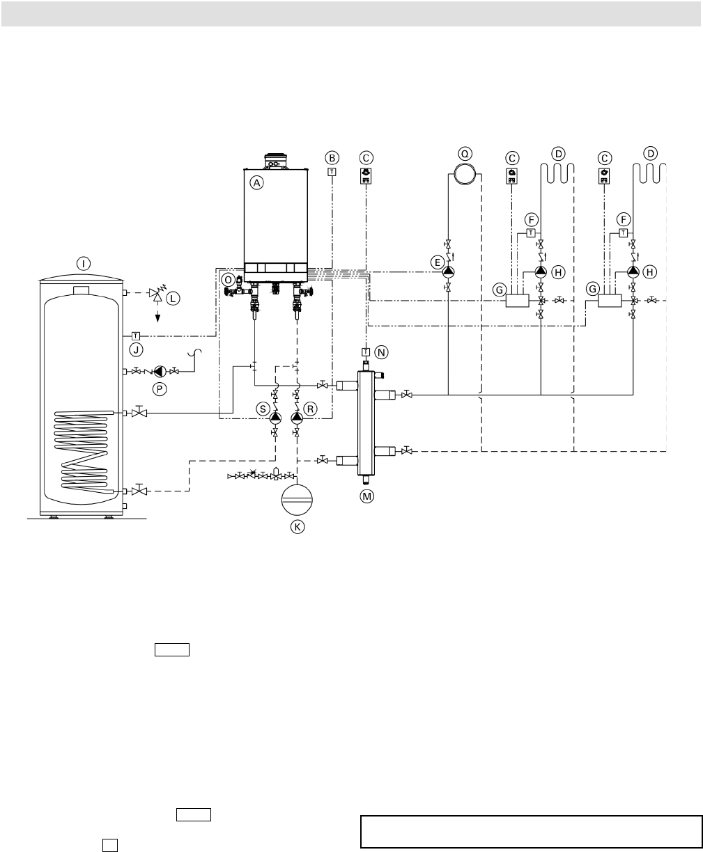
5683 718 - 04
Installation Examples
System Layout 6
Vitodens 200-W B2HA 100 to 150 Technical Data
Vitodens 200-W, B2HA with...
- DHW storage tank
- one heating circuit without a mixing valve
- two heating circuits with a mixing valve
- low-loss header
Installation of different heating circuits...
■ two heating circuits with 3-way mixing valve
(low-temp. circuit)
■ DHW production
... with the following flow conditions:
The total flow rate of the two heating circuits is greater
than the maximum possible water flow rate of the
Vitodens 200-W B2HA boiler (see page 9 for maximum
water flow rate of boiler).
The use of a low-loss header is strongly recommended.
The low-loss header is available as accessory part.
The 3-way mixing valve, built-in to achieve the low-
temperature level of the under floor heating circuit, is
controlled by an accessory kit for a heating circuit with
a mixing valve.
DHW circulating pump S must pump into the Vitodens
200-W B2HA boiler (as illustrated).
IMPORTANT
Legend
A Vitodens 200-W B2HA boiler with
Vitotronic 200, HO1B outdoor reset control
B Outdoor temperature sensor !
C Vitotrol remote (optional)
D Under floor heating circuit
E Heating circuit pump 28/20 *
F Mixing valve temperature sensor ?
G Accessory kit for heating circuit with mixing valve
H Heating circuit pumps
I DHW storage tank
J DHW tank temperature sensor %
K Expansion tank
L Temperature and pressure relief valve
M Low-loss header
N Viessmann temperature sensor for low-loss header ?
O Pressure relief valve
P DHW recirculation pump 28/20 *
Q Radiator heating circuit
R Boiler pump 20
S DHW circulating pump sA
* Function based on coding of address 33
39
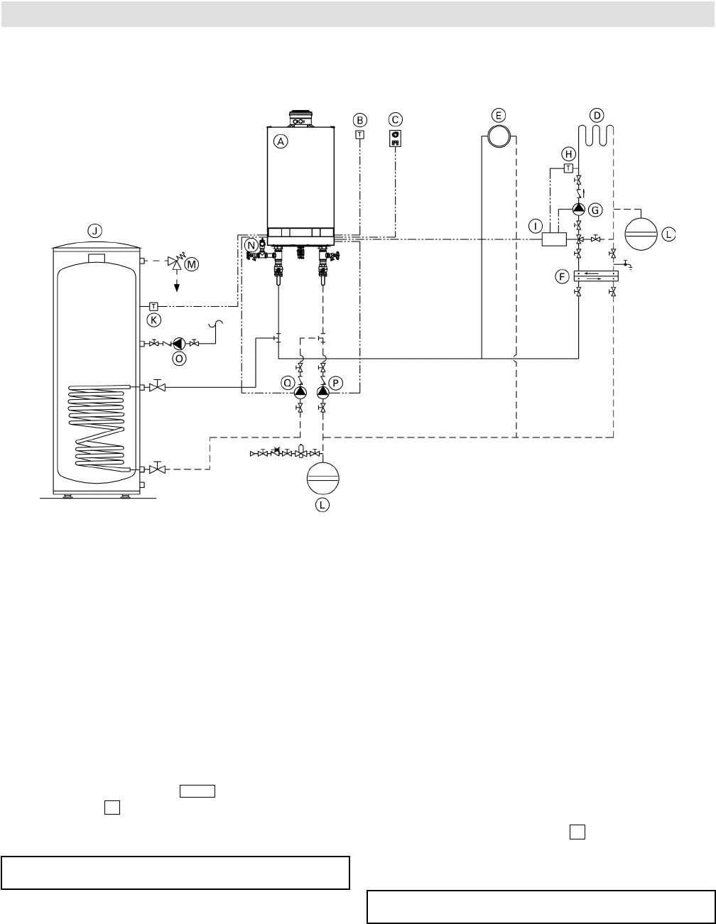
5683 718 - 04
Vitodens 200-W B2HA 100 to 150 Technical Data
Installation Examples
40
System Layout 7
Vitodens 200-W, B2HA with...
- direct-connected heating circuit
- one heating circuit with system separation
IMPORTANT
IMPORTANT
Installation of different heating circuits...
■ radiator heating circuit (high-temp. circuit)
■ under floor heating circuit with 3-way mixing valve
(low-temp. circuit)
■ DHW production
... with the following flow conditions:
The total flow rate of the two heating circuits is less than
the maximum possible water flow rate of the Vitodens
200-W B2HA boiler (see page 9 for maximum water flow
rate of boiler).
The use of a low-loss header is strongly recommended if
the maximum water flow rate in the application concerned
exceeds the max. boiler flow rate, or if the system flow
rates are unknown. The low-loss header is available as
accessory part.
The 3-way mixing valve, built-in to achieve the low-
temperature level of the under floor heating circuit, is
controlled by an accessory kit for a heating circuit with
mixing valve I. The boiler pump 20 supplies the
radiator heating circuit and the plate heat exchanger
for system separation.
The pressure drop (secondary circuit) of the plate heat
exchanger F must be less/equal to the pressure drop of
the 3-way mixing valve. This must be taken into account
when sizing the plate heat exchanger.
Legend
A Vitodens 200-W B2HA boiler with Vitotronic 200,
HO1B outdoor reset control
B Outdoor temperature sensor !
C Vitotrol remote (optional)
D Under floor heating circuit
E Radiator heating circuit
F Plate heat exchanger for system separation
G Heating circuit pump
H Mixing valve temperature sensor ?
I Accessory kit for heating circuit with mixing valve
J DHW storage tank
K DHW tank temperature sensor %
L Expansion tanks
M Temperature and pressure relief valve
N Pressure relief valve
O DHW recirculation pump 28/20 *
P Boiler pump 20
Q DHW circulating pump sA
* Function based on coding of address 33
DHW circulating pump Q must pump into the Vitodens
200-W B2HA boiler (as illustrated).
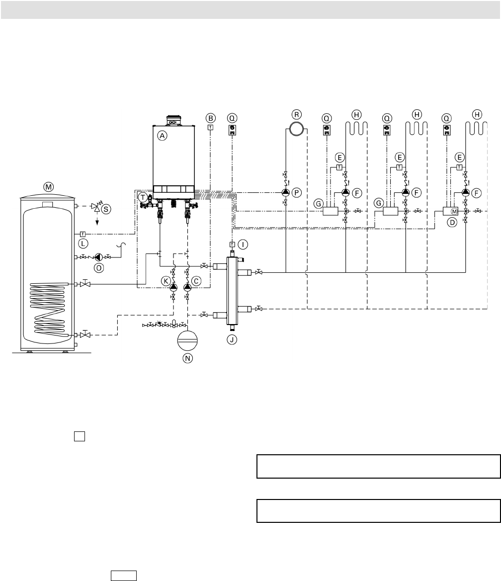
41
5683 718 - 04
Vitodens 200-W B2HA 100 to 150 Technical Data Installation Examples
System Layout 8
Vitodens 200-W, B2HA with...
- DHW storage tank
- low-loss header
- multiple heating circuits with mixing valves
- one heating circuit without mixing valve
When designing a system as illustrated above, please contact your local Viessmann Sales Representative for assistance.
*1 Contact your local Sales Representative for details.
Vitotronic 200-H, HK1B mixing valve control with
LON communication module can be used instead
of the accessory kit and Vitocontrol.
Please note location of expansion tank N.
Pumps C and K must pump into the Vitodens 200-W
B2HA boiler (as illustrated).
IMPORTANT
IMPORTANT
Legend
A Vitodens 200-W B2HA boiler with Vitotronic
200, HO1B outdoor reset control
B Outdoor temperature !
C Boiler pump 20
D Vitotronic 200-H, HK1B *1
E Mixing valve temperature sensor ?
F Heating circuit pumps
G Accessory kit for heating circuit with mixing valve
H Heating circuits with mixing valves
I Viessmann temperature sensor for low-loss header ?
J Low-loss header
K DHW circulating pump sA
L DHW tank temperature sensor %
M DHW storage tank
N Expansion tank
O DHW recirculation pump sK
P Heating circuit pump 28/20 *
Q Vitotrol remote (optional)
R Radiator heating circuit
S Temperature and pressure relief valve
T Pressure relief valve
* Function based on coding of address 33
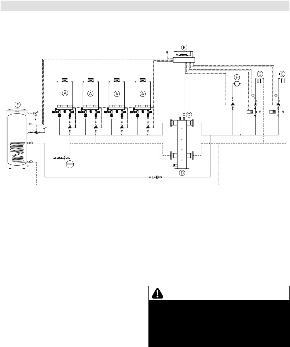
5683 718 - 04
Vitodens 200-W B2HA 100 to 150 Technical Data
Installation Examples
System Layout 9
42
Multiple (up to eight) Vitodens 200-W, models B2HA 100 to 150 with...
- multiple heating circuits with mixing valves
- low-loss header
When designing a multiple Vitodens system as shown
above, please reference applicable multiple Vitodens
technical documentation, and contact your local Viessmann
Sales Representative for further assistance.
This installation example depicts a possible piping layout
for multiple Vitodens 200-W, B2HA boilers equipped with
Viessmann System Technology. Please note that this
example is based on a simplified conceptual drawing only!
Piping and necessary componentry must be field verified.
A low water cut-off (LWCO) must be installed where
required by local codes.
Proper installation and functionality in the field is the
responsibility of the heating contractor.
WARNING
If a DHW storage tank other than a Viessmann
Vitocell 100 or 300 tank is used, the installer must
verify proper operation of the Viessmann DHW tank
temperature sensor with the original manufacturer
of the tank. Viessmann strongly recommends the
installation of a temperature tempering valve in the
DHW supply line.
Legend
A Vitodens boiler
B Vitotronic 300K
C Low-loss header/common supply temperature sensor
D Low-loss header
E DHW storage tank
F High temperature heating circuit
G Low temperature heating circuit

43
5683 718 - 04
Vitodens 200-W B2HA 100 to 150 Technical Data Installation Examples
Alternative DHW Connection
The following piping diagram reflects an alternative connection for the DHW tank only and applies to system layouts
2, 5, 6 and 8. The boiler control pump logic function must be programmed in the Service Instructions.
*Note: When using a low loss header in the system, the
DHW connections can be made downstream of
the low loss header. See Vitodens 200-W B2HA
Service Instructions for applicable system coding
information (see coding level 2):
00: ...
A2: ...
5b: ...
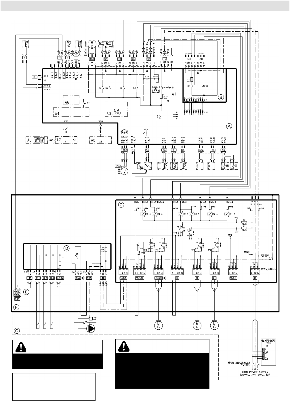
Vitodens 200-W B2HA 100 to 150 Technical Data
Wiring Diagram
Overview of Electrical Connections, Models B2HA 100
5683 718 - 04
44
If any of the original wires as
supplied with the appliance must
be replaced, it must be replaced
with the exact equivalent.
CAUTION
Label all wires prior to disconnection
when servicing controls. Wiring errors
can cause improper and dangerous
operation. Verify proper operation
after servicing.
* Only one function/accessory may
be assigned to each connection.
WARNING
DISCONNECT POWER BEFORE
SERVICING BOILER.

Vitodens 200-W B2HA 100 to 150 Technical Data
45
Wiring Diagram
Overview of Electrical Connections, Models B2HA 100 (continued)
A Boiler Control
B External Accessory Connection Board
C Pump Connection Interface
D Extension Module EA1
E KM-BUS for External Devices
F Electrical Junction Box
G Field Wiring Connections
A1 Main Board
A2 Internal Power Supply Unit
A3 Optolink
A4 Burner Control Unit
A5 Programming Unit
A6 Coding Card
A7 Connection Adaptor
A8 LON Communication Module
S1 ON/OFF Switch
S2 Reset Button
X.. Electrical Interface
Legend
1 Outdoor Temperature Sensor
2 Supply Temperature Sensor/Low Loss Header
3 Boiler Temperature Sensor/High Limit Sensor
3A Boiler Temperature Sensor/High Limit Sensor
5 DHW Temperature Sensor
11 Ionization Electrode
15 Flue Gas temperature Sensor
20 Boiler Pump
21 DHW Pump
[21] Pump Output Connection
28/20 Programmable Pump Output*
33 Flow Switch (X2 FOR MODELS 80/100)
35 Gas Valve (X2 FOR MODELS 80/100)
40 Power Supply
40A Accessory Power Output
[53] Powered Accessory Connection
54 Ignition Transformer
96 Powered Accessory Connection
100 Fan Motor
100A Fan Motor Control
111 Not Used
145 KM-BUS
Multi Powered Accessory Connection
156A Switched Output F2
156B Switched Output F1
DE1 Digital Input 1 (Dry Contact)
DE2 Digital Input 2 (Dry Contact)
DE3 Digital Input 3 (Dry Contact)
0-10V 0-10VDC Input
157 Fault Alarm/DHW Recirc. Pump*
190 Gas Modulation Coil
190A Gas Modulation Coil (for 80/100)
* See wiring diagram
5683 718 - 04
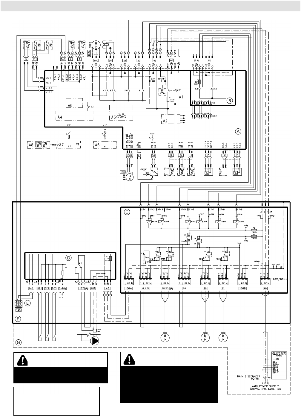
5683 718 - 04
46
Wiring Diagram
Overview of Electrical Connections, Models B2HA 112 and 150
Vitodens 200-W B2HA 100 to 150 Technical Data
If any of the original wires as
supplied with the appliance must
be replaced, it must be replaced
with the exact equivalent.
CAUTION
Label all wires prior to disconnection
when servicing controls. Wiring errors
can cause improper and dangerous
operation. Verify proper operation
after servicing.
* Only one function/accessory may
be assigned to each connection.
WARNING
DISCONNECT POWER BEFORE
SERVICING BOILER.

47
5683 718 - 04
Wiring Diagram
Overview of Electrical Connections, Models B2HA 112 and 150 (continued)
Vitodens 200-W B2HA 100 to 150 Technical Data
A Boiler Control
B External Accessory Connection Board
C Pump Connection Interface
D Extension Module EA1
E KM-BUS for External Devices
F Electrical Junction Box
G Field Wiring Connections
A1 Main Board
A2 Internal Power Supply Unit
A3 Optolink
A4 Burner Control Unit
A5 Programming Unit
A6 Coding Card
A7 Connection Adaptor
A8 LON Communication Module
S1 ON/OFF Switch
S2 Reset Button
X.. Electrical Interface
Legend
1 Outdoor Temperature Sensor
2 Supply Temperature Sensor/Low Loss Header
3 Boiler Temperature Sensor/High Limit Sensor
3A Boiler Temperature Sensor/High Limit Sensor
5 DHW Temperature Sensor
11 Ionization Electrode
15 Flue Gas temperature Sensor
20 Boiler Pump
21 DHW Pump
[21] Pump Output Connection
28/20 Programmable Pump Output*
35 Gas Valve
40 Power Supply
40A Accessory Power Output
[53] Powered Accessory Connection
54 Ignition Transformer
96 Powered Accessory Connection
100 Fan Motor
100A Fan Motor Control
111 Low and High Pressure Gas Switches
145 KM BUS
Multi Powered Accessory Connection
156A Switched Output F2
156B Switched Output F1
DE1 Digital Input 1 (Dry Contact)
DE2 Digital Input 2 (Dry Contact)
DE3 Digital Input 3 (Dry Contact)
0-10V 0-10VDC Input
157 Fault Alarm/DHW Recirc. Pump*
190 Gas Modulation Coil
F Flow Sensor
* See wiring diagram

5683 718 - 04
Vitodens 200-W B2HA 100 to 150 Technical Data
System Design
System Design Considerations
IN THE COMMONWEALTH OF MASSACHUSETTS...
- this product shall be installed by a licensed plumber or
gas fitter.
- the flexible connector (if used) cannot exceed 36”.
- any level type shutoff used must be of tee handle
type.
Boiler location
As a direct vent appliance, the Vitodens 200-W can
be installed for room air independent operation (sealed
combustion) regardless of size and ventilation method
of the room in which it is located.
The Vitodens 200-W can be installed, for example, in
the main living area of a house, in non-ventilated utility
rooms, cupboards, closets and alcoves with no clearance
required from combustible materials, as well as in attics
with a direct outlet for the flue gas/fresh air system.
Follow all local and national codes.
Flue gas system
Viessmann PPS (Polypropylene) concentric flue gas/
fresh air systems for room air independent operation
(sealed combustion) and side wall venting are tested
to ANSI Z21.13 - CSA 4.9 - 2000 standards and are
certified together with the Vitodens 200-W boiler as a
constructional unit.
The Vitodens 200-W boiler may also be vented vertically,
using an AL29-4C® special stainless steel, single-wall, room
air dependent venting system (UL listed for category IV).
For a more detailed description of the direct vent and
single-wall vent system, please refer to the Vitodens 200-W
Venting System Installation Instructions.
Flue gas temperature protection
Flue pipes used for the Vitodens 200-W are suitable for
max. flue gas temperatures of up to 230° F (110° C).
No flue gas temperature protection is required as the
maximum permissible flue gas temperature is not
exceeded in any operating condition or in the event of
malfunctioning.
Low water cut-off
A low water cut-off may be required by local codes.
If the boiler is installed above the radiation level, a low
water cut-off device of approved type must be installed
in all instances. An approved type low water cut-off
device must be provided by the heating contractor.
Do not install an isolation valve between the boiler and
the low water cut-off.
Water connections
Vitodens 200-W boilers can be used in any fully pumped
hot water heating system.
Minimum system pressure is 0.8 bar (12 psig).
Chemical corrosion protection products
Corrosion does not typically occur in sealed heating
systems which have been correctly installed and are
correctly operated.
Many manufacturers of plastic pipes recommend the
use of chemical additives. In this case, only those
commercially available corrosion protection products
approved for boilers with domestic hot water heating
via single-wall heat exchangers (instantaneous plate
heat exchangers or DHW tanks) must be used.
Water quality
Treatment for boiler feed water should be considered in
areas of known problems, such as where a high mineral
content and hardness exist. In areas where freezing might
occur, an antifreeze may be added to the system water
to protect the system. Please adhere to the specifications
given by the antifreeze manufacturer. Do not use
automotive silicate based antifreeze.
Please observe that an antifreeze/water mixture may
require a backflow preventer within the automatic water
feed and influence components such as diaphragm
expansion tanks, radiation, etc. Maximum antifreeze
content is 50% for the Vitodens 200-W boiler. Do not
use antifreeze other than specifically made for hot water
heating systems. System also may contain components
which might be negatively affected by antifreeze.
Check total system frequently when filled with antifreeze.
Advise system operator/ultimate owner that system is
filled with a glycol mix. The heating contractor must
provide a MSDS (Material Safety Data Sheet) for the
antifreeze used to the system operator/ultimate owner.
48
Total permissible hardness of the fill and top-up water
Total heating output Specific heating volume
MBH <5 USG per 3412 BTU m 5USG per 3412 BTU to
<13USG per 3412 BTU
m 13USG per 3412 BTU
[ 170 300 ppm 17.5 gpg 200 ppm 11.7 gpg 2 ppm 0.11 gpg
>170 to [ 682 200 ppm 11.7 gpg 150 ppm 8.8 gpg 2 ppm 0.11 gpg
>682 to [170 150 ppm 8.8 gpg 2 ppm 0.11 gpg 2 ppm 0.11 gpg
>2050 2 ppm 0.11 gpg 2 ppm 0.11 gpg 2 ppm 0.11 gpg
ppm - parts per million
gpg - grains per gallon

49
5683 718 - 04
Vitodens 200-W B2HA 100 to 150 Technical Data System Design
System Design Considerations (continued)
System layout
■ The max. boiler water temperature for space heating
and DHW production is for model B2HA 100.
To minimize distribution losses, Viessmann
recommends that the heating and domestic hot water
systems be based on a maximum boiler supply
temperature of 158° F (70° C).
■ Due to the low return temperatures required for gas
condensing, no mixing valves should be used in the
heating circuit whenever possible. If mixing valves
are required, e.g. for multi-circuit systems or
underfloor heating systems, only 3-way mixing valves
must be used.
Do not use 4-way mixing valves with condensing
boilers.
Underfloor heating systems
For underfloor heating systems Viessmann recommends
the use of plastic tubing with an oxygen diffusion barrier
in order to prevent the diffusion of oxygen through
tubing. If plastic tubing without an oxygen diffusion
barrier is used in underfloor heating systems, Viessmann
recommends that such systems be separated from the
boiler with a heat exchanger.
Underfloor heating systems and heating circuits
containing a very large volume of water must be
connected to the boiler via a 3-way mixing valve; please
refer to the applicable installation example in this manual.
Oxygen diffusion barrier underfloor tubing
The boiler warranty does not cover leaks resulting from
corrosion caused by the use of underfloor plastic tubing
without an oxygen diffusion barrier. Such systems must
have the non-oxygen diffusion barrier tubing separated
from the boiler with a heat exchanger. Viessmann
recommends the use of underfloor plastic tubing with
an oxygen diffusion barrier.
Warranty
Our warranty does not cover damages resulting from
the following:
- installation or service by unqualified and unlicensed
personnel.
- attempting to perform any repair work on the boiler
other than that mentioned in the boiler literature.
- tampering with or attempting, without Viessmann
permission, to readjust the factory settings of the;
-combination gas valve
-combustion air opening of the burner blower
- leaks resulting from corrosion caused by the use of
underfloor plastic tubing without an oxygen diffusion
barrier. For detailed warranty information, please read
warranty sheet supplied with product.

Vitodens 200-W B2HA 100 to 150 Technical Data
5683 718 - 04
50

Vitodens 200-W B2HA 100 to 150 Technical Data
51
5683 718 - 04
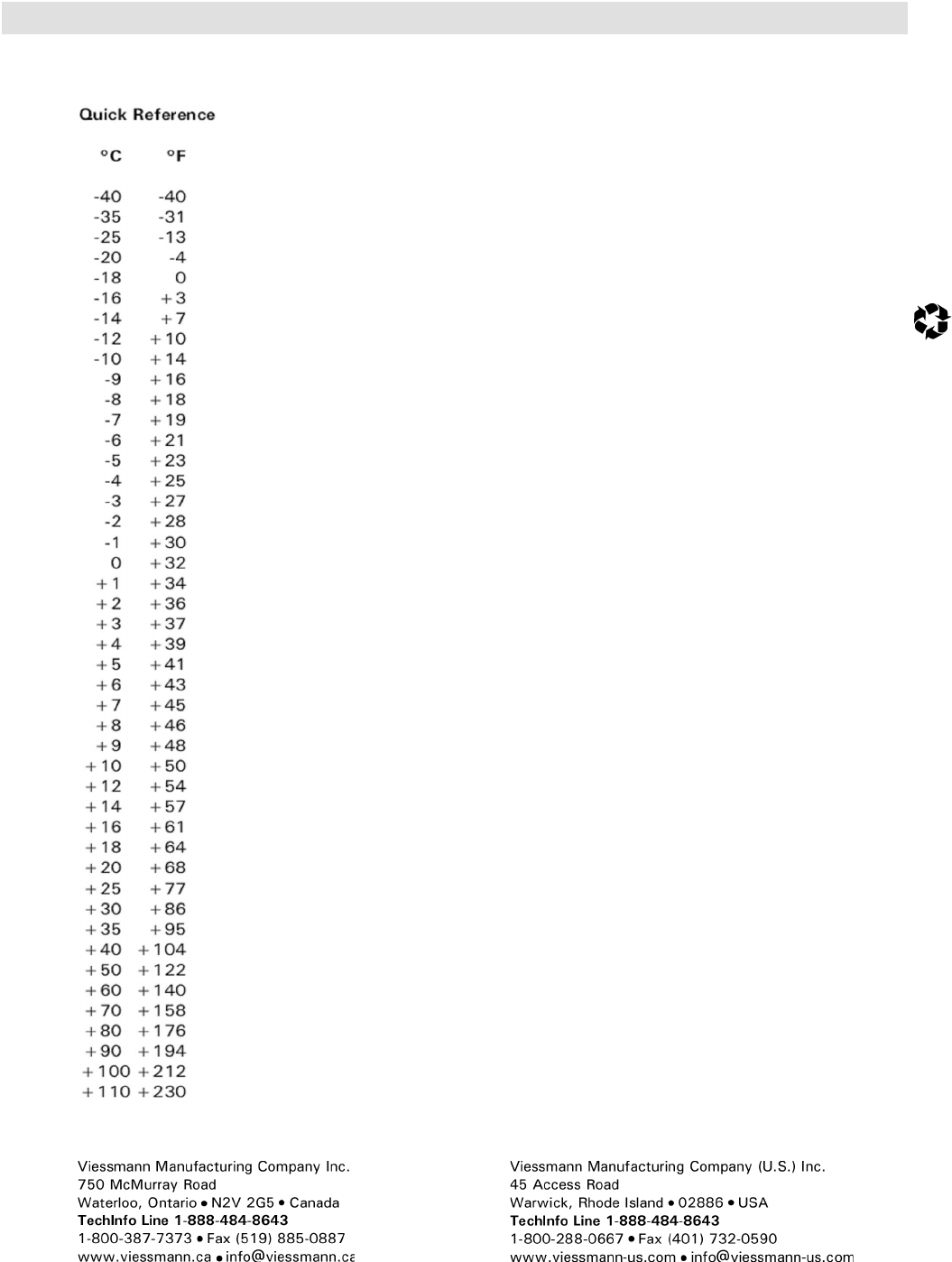
Technical information subject to change without notice. Printed on environmentally friendly
(recycled and recyclable) paper.
Vitodens 200-W B2HA 100 to 150 Technical Data
5683 718 - 04
