Vieworks FXRD1417N X-ray Detector User Manual ViVIX S 1417W x
Vieworks Co., Ltd. X-ray Detector ViVIX S 1417W x
Vieworks >
Contents
- 1. User Manual Part 1
- 2. User Manual Part 2
User Manual Part 1
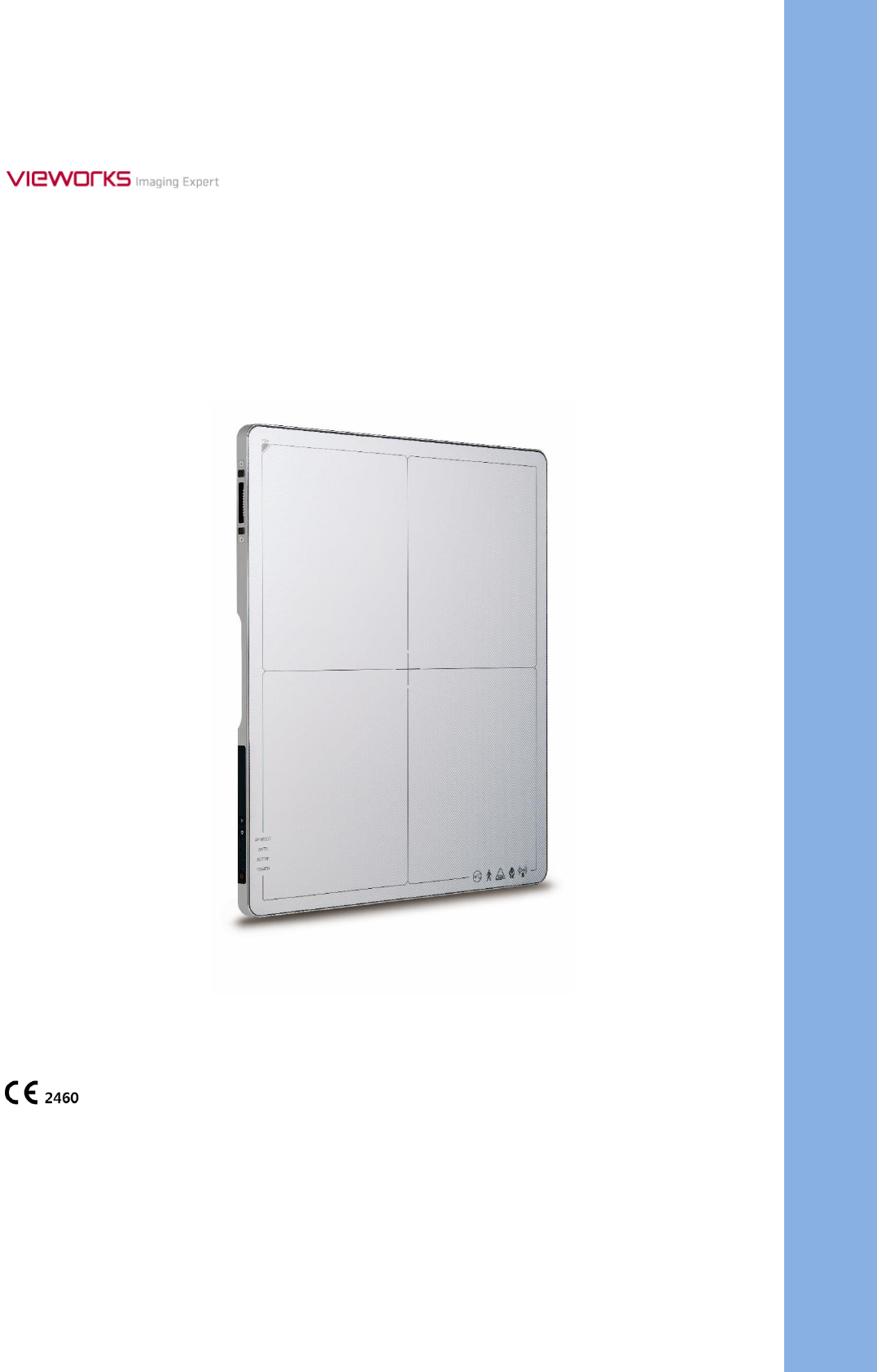
VIVIX-S 1417N User Manual
© Vieworks. 2017 All rights reserved.
The specifications and related information in this manual may be changed without notice. Refer to Vieworks
Download Syetem (VDS) for the latest version of manuals.
Under copyright laws, this manual should not be reproduced, in whole or in part, without the written
permission of Vieworks.

Rev.1.5
Page 2 of 121 D-16-207
VIVIX-S 1417N User Manual
Contents
1. Instruction ......................................................................................................................................... 7
1.1 Document Guide ..................................................................................................................................... 8
1.1.1 Caution ............................................................................................................................................................................... 8
1.1.2 Target Audience .............................................................................................................................................................. 8
1.1.3 Symbols .............................................................................................................................................................................. 8
1.1.4 Notations ........................................................................................................................................................................... 8
1.1.5 Contact Department ..................................................................................................................................................... 8
1.2 Intended Use ............................................................................................................................................ 9
1.2.1 Features .............................................................................................................................................................................. 9
1.3 Product Use ............................................................................................................................................ 10
1.3.1 Product Usage ...............................................................................................................................................................10
1.3.2 Disclaimer ........................................................................................................................................................................10
1.3.3 Product Disposal ..........................................................................................................................................................11
1.3.4 Trademarks ......................................................................................................................................................................11
1.4 Safety Instruction .................................................................................................................................. 12
1.4.1 Management and Authority ...................................................................................................................................12
1.4.2 Power Supply .................................................................................................................................................................12
1.4.3 Handling...........................................................................................................................................................................13
1.4.4 Battery Pack and Charger ........................................................................................................................................14
1.4.5 Environment of Use ....................................................................................................................................................15
1.4.6 Temperature ...................................................................................................................................................................16
1.4.7 Problem Management ...............................................................................................................................................16
1.4.8 Maintenance and Inspection ..................................................................................................................................16
1.5 Product Usage Guide............................................................................................................................ 17
1.5.1 Calibration .......................................................................................................................................................................17
1.5.2 Length Measurement .................................................................................................................................................17
1.5.3 Left/Right Marker.........................................................................................................................................................17
1.5.4 Image Backup ................................................................................................................................................................17
1.5.5 Use Limitations .............................................................................................................................................................18
1.5.6 Disposal ............................................................................................................................................................................18
1.5.7 Pediatric Application ..................................................................................................................................................18
1.5.8 Before Exposure ............................................................................................................................................................18
1.5.9 During Exposure ...........................................................................................................................................................19
1.5.10 Operating and Storage Environment .................................................................................................................19
1.5.11 Others................................................................................................................................................................................19
2. Product ............................................................................................................................................. 20

Rev.1.5
Page 3 of 121 D-16-207
VIVIX-S 1417N User Manual
2.1 Product Components............................................................................................................................ 21
2.1.1 Detector............................................................................................................................................................................21
2.1.2 SCU Lite (FXRP-02A) ...................................................................................................................................................21
2.1.3 SCU (System Control Unit) ......................................................................................................................................22
2.1.4 Battery & Charger .......................................................................................................................................................23
2.1.5 Accessories ......................................................................................................................................................................24
2.2 VIVIX-S 1417N Detector ...................................................................................................................... 26
2.2.1 Specifications .................................................................................................................................................................26
2.2.2 Drawing Sheet ...............................................................................................................................................................27
2.2.3 Functions..........................................................................................................................................................................28
2.2.4 Deco Sheet .....................................................................................................................................................................30
2.2.5 Wireless Communication..........................................................................................................................................31
2.2.6 Use Environment ..........................................................................................................................................................31
2.3 SCU Basic (FXRS-03A) .......................................................................................................................... 32
2.3.1 Specifications .................................................................................................................................................................32
2.3.2 Drawing Sheet ...............................................................................................................................................................32
2.3.3 Functions..........................................................................................................................................................................33
2.4 SCU mini (FXRS-04A) ............................................................................................................................ 35
2.4.1 Specifications .................................................................................................................................................................35
2.4.2 Drawing Sheet ...............................................................................................................................................................35
2.4.3 Functions..........................................................................................................................................................................36
2.5 SCU Lite (FXRP-02A) ............................................................................................................................. 38
2.5.1 Specifications .................................................................................................................................................................38
2.5.2 Drawing Sheet ...............................................................................................................................................................38
2.5.3 Functions..........................................................................................................................................................................39
2.6 Battery Pack ........................................................................................................................................... 40
2.6.1 Specifications .................................................................................................................................................................40
2.6.2 Drawing Sheet ...............................................................................................................................................................40
2.7 Battery Charger (FXRC-02A) ............................................................................................................... 41
2.7.1 Specifications .................................................................................................................................................................41
2.7.2 Drawing Sheet ...............................................................................................................................................................41
2.8 Battery Charger (FXRC-03A) ............................................................................................................... 42
2.8.1 Specifications .................................................................................................................................................................42
2.8.2 Drawing Sheet ...............................................................................................................................................................42
2.9 Others ...................................................................................................................................................... 43
2.9.1 X-ray Generator (Recommended Exposure Condition)..............................................................................43
2.9.2 Recommended Specifications of Workstation (PC) .....................................................................................43

Rev.1.5
Page 4 of 121 D-16-207
VIVIX-S 1417N User Manual
2.9.3 Recommended Specifications of Grid ................................................................................................................43
3. System Configuration.................................................................................................................... 44
3.1 Detector Connection Methods ........................................................................................................... 45
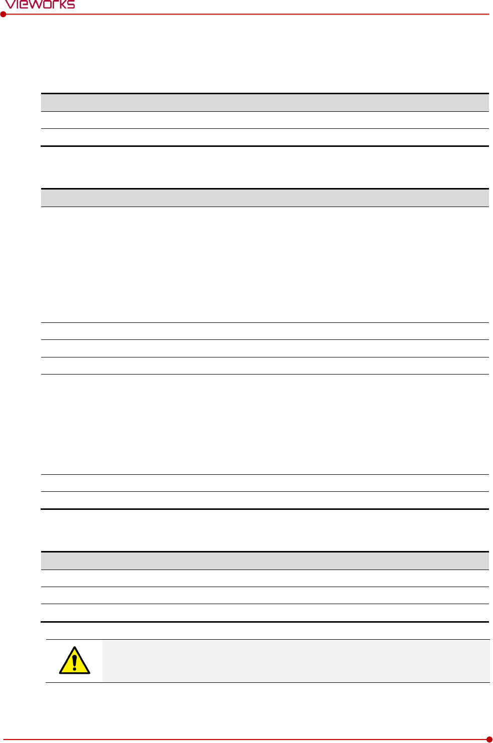
3.1.1 Wireless Connection ...................................................................................................................................................45
3.1.2 Wired Connection ........................................................................................................................................................46
3.2 Diagram................................................................................................................................................... 47
3.2.1 Block Diagram ...............................................................................................................................................................47
3.2.2 Wiring Diagram ............................................................................................................................................................47
3.3 System Configuration ........................................................................................................................... 48
3.3.1 AP Mode (SCU AP Mode)........................................................................................................................................48
3.3.2 Tether Interface Mode ...............................................................................................................................................49
3.3.3 External AP Mode ........................................................................................................................................................50
3.3.4 Detector AP Mode ......................................................................................................................................................51
3.3.5 Detector Stand-Alone Mode ..................................................................................................................................52
3.4 Generator Interface............................................................................................................................... 53
3.4.1 AED (Auto Exposure Detection) Interface ........................................................................................................53
3.4.2 DR Trigger Interface ...................................................................................................................................................54
3.5 Configuring DR Trigger Interface ...................................................................................................... 55
3.5.1 Trigger Interface Way .................................................................................................................................................55
3.5.2 Packet Trigger ................................................................................................................................................................55
3.5.3 Line Trigger .....................................................................................................................................................................56
3.5.4 EXT_INF Port Pin Map ...............................................................................................................................................57
3.5.5 Input / Output Circuit ................................................................................................................................................59
4. Settings ............................................................................................................................................ 60
4.1 Battery Pack ........................................................................................................................................... 61
4.1.1 How to Insert Battery Packs ...................................................................................................................................61
4.1.2 How to take out a battery pack ...........................................................................................................................62
4.1.3 How to charge a battery pack (FXRC-02A) .....................................................................................................65
4.1.4 How to charge a battery pack (FXRC-03A) .....................................................................................................67
4.2 Product Installation .............................................................................................................................. 70
4.2.1 Connecting SCU Basic (FXRS-03A) ......................................................................................................................70
4.2.2 Connecting SCU mini (FXRS-04A) ........................................................................................................................71
4.2.3 Booting up SCU (Ex. FXRS-03A)............................................................................................................................72
4.2.4 Booting up the Detector ..........................................................................................................................................72
4.2.5 Checking Status LED of Detector .........................................................................................................................73
4.2.6 Connecting SCU Lite (FXRP-02A) .........................................................................................................................75
4.2.7 Booting Up SCU Lite and Detector .....................................................................................................................76

Rev.1.5
Page 5 of 121 D-16-207
VIVIX-S 1417N User Manual
4.3 Device Setting ........................................................................................................................................ 77
4.3.1 Software Installation ...................................................................................................................................................77
4.3.2 Setting Detector and SCU .......................................................................................................................................77
4.3.3 Setting NFC Tag............................................................................................................................................................77
4.4 Diagnosis of Devices ............................................................................................................................ 79
4.4.1 Image Diagnosis ...........................................................................................................................................................79
4.4.2 Battery Pack Diagnosis ..............................................................................................................................................80
4.4.3 Wireless Communication Diagnosis ....................................................................................................................81
4.4.4 Wired/Wireless Communication Speed Diagnosis .......................................................................................82
4.4.5 Self-Diagnosis ................................................................................................................................................................82
5. Inspection and Maintenance ....................................................................................................... 85
5.1 Product Inspection ................................................................................................................................ 86
5.1.1 Daily Inspection ............................................................................................................................................................86
5.1.2 Performance Inspection ............................................................................................................................................86
5.2 Cleaning and Disinfection ................................................................................................................... 87
5.2.1 Recommended Detergent Foam ..........................................................................................................................87
5.2.2 How to Use Detergent Foam .................................................................................................................................87
5.3 Product Initialization ............................................................................................................................ 88
5.3.1 SCU Initialization ..........................................................................................................................................................88
5.3.2 Detector Initialization .................................................................................................................................................89
5.3.3 Wireless Initialization of Detector ........................................................................................................................90
5.4 Detector Power Save Function (Sleep) .............................................................................................. 91
5.5 Changing the Wireless Setting ........................................................................................................... 93
5.5.1 Switching to the Detector AP Mode ..................................................................................................................93
5.5.2 Synchronizing the Wireless Setting .....................................................................................................................93
5.6 Replacing the Fuse of SCU .................................................................................................................. 94
6. Troubleshooting ............................................................................................................................. 95
6.1 Troubleshooting .................................................................................................................................... 96
6.1.1 Troubleshooting Guide ..............................................................................................................................................96
6.1.2 Fail to Turn the Detector On ..................................................................................................................................96
6.1.3 The Power Switch of SCU or Status LED is not worked ............................................................................96
6.1.4 The Power Switch of SCU Lite is not Working ...............................................................................................97
6.1.5 Communication Test is failed .................................................................................................................................97
6.1.6 The Active LED and Data LED of the Detector are blinking....................................................................98
6.1.7 Errors in Detector LED ...............................................................................................................................................98
6.1.8 Rapid Consumption of Battery ..............................................................................................................................98
6.1.9 Battery Pack or Installation Part of Battery is Getting Hot ......................................................................98

Rev.1.5
Page 6 of 121 D-16-207
VIVIX-S 1417N User Manual
7. Regulatory Information ................................................................................................................ 99
7.1 Medical Equipment Safety Standards ............................................................................................. 100
7.1.1 Medical Equipment Classification ..................................................................................................................... 100
7.1.2 Product Safety Standard ........................................................................................................................................ 100
7.2 Radio Frequency Compliance Information ..................................................................................... 102
7.2.1 FCC Compliance ........................................................................................................................................................ 102
7.2.2 FCC SAR ........................................................................................................................................................................ 103
7.2.3 CE R&TTE SAR............................................................................................................................................................ 103
7.3 Labels and Symbols ............................................................................................................................ 105
7.3.1 Label................................................................................................................................................................................ 105
7.3.2 Product Serial Number........................................................................................................................................... 112
7.3.3 Product Symbols ....................................................................................................................................................... 113
7.4 Guidance and Manufacturer’s Declaration for EMC ..................................................................... 115
7.4.1 Electromagnetic Emissions ................................................................................................................................... 115
7.4.2 Electromagnetic Immunity .................................................................................................................................... 115
8. Information ................................................................................................................................... 118
8.1 Service Information ............................................................................................................................ 119
8.1.1 Product Lifetime ........................................................................................................................................................ 119
8.1.2 Regular Inspection and Maintenance.............................................................................................................. 119
8.1.3 Repair ............................................................................................................................................................................. 119
8.1.4 Replacement Parts Support ................................................................................................................................. 119
8.1.5 Consumables............................................................................................................................................................... 119
8.2 Warranty ............................................................................................................................................... 120
8.3 Revision History .................................................................................................................................. 121

Rev.1.5
Page 7 of 121 D-16-207
VIVIX-S 1417N User Manual
1. Instruction
This section gives basic information about this manual and safe product use.
Document Guide
Intended Use
Product Use
Safety Instruction
Product Usage Guide
Rev.1.5
Page 8 of 121 D-16-207
VIVIX-S 1417N User Manual
1.1 Document Guide
This User Manual explains how to use the VIVIX-S 1417N detector made by Vieworks, X-ray interface unit,
and other peripheral equipment. Use this manual to install, set up and manage the VIVIX-S 1417N
detector as well as understand its various functions.
1.1.1 Caution
If the user is not fully aquainted with this manual, the product can be malfunctioned or unsuspected
problem can be happened due to carelessness. To prevent any medical accidents, the user should fully
understand the instructions of this manual before operating this product.
1.1.2 Target Audience
This manual is intended for service engineers and users who install and set up the VIVIX-S 1417N detector.
1.1.3 Symbols
This product should be operated under the safety instructions with the warning or caution symbol in this
manual. It is important for you to read and understand the contents to operate the products safely.
Caution and Warning
This symbol is used to indicate a potentially hazardous situation that may cause death,
personal injury or substantial property damage if the instructions for safe operation are
ignored.
Information
This symbol is used to indicate reference and complementary information. Users are
encouraged to read this information carefully.
1.1.4 Notations
Bold Types
We applied bold font style to the words which mean the products terms, or the words and sentences that
are needed to transmit clear meaning to the customers. This helps you to easily distinguish the words from
other technical ones for explaining functions.
1.1.5 Contact Department
For comments or inquiries regarding this document and relevant products, contact via email below.
Item
Contents
Department
Customer Support Team in Vieworks
E-mail
CustomerSupport@vieworks.com

Rev.1.5
Page 9 of 121 D-16-207
VIVIX-S 1417N User Manual
1.2 Intended Use
VIVIX-S 1417N detector is a digital X-ray imaging solution. It acquires images by detecting X-rays that has
been passed through the human body. When X-ray photons pass through the scintillator in the detector,
the photons convert to visible ray, and the visible ray is converted to electronic signals through TFTs – thin
film transistors (a-Si). Then the detector digitalizes X-ray images and transfers them to the PC (workstation)
for diagnostic review using an image display monitor. Advanced digital image processing also allows
efficient diagnosis, information management, and sharing of image information over the network.
This detector is used for the general-purpose diagnostic procedures, and as well as
intended to replace radiographic film / screen systems.
This detector is not intended for mammography applications.
1.2.1 Features
Since VIVIX-S 1417N detector is compatible with a conventional film cassette, it enables to replace the
analog radiographic diagnosis.
The new sensor with 140μm of pixel pitch produces high spatial resolution (approximately 7.9 Mega
pixels) digital images.
You can choose between two scintillator types (CsI and Gadox) of a detector provided by Vieworks.
The built-in wireless communication supports IEEE 802.11n/ac to acquire images without a wired
connection in anytime, anywhere.
Easily changes the settings of your detector using NFC tag.
Checks the connecting status and battery remains through the LED display.
Makes direct wireless communication with the built-in wireless AP function. (Inside APTM)
Makes quick application of various functions with the buttons on the side of the detector.
Supports the stable and reliable AED (Auto Exposure Detection) function. (AnytimeTM)
Designed as lightweight and thin with portability to allow easy exposure in anytime, anywhere.
Used the devices with cable connection (tether interface cable) depending on the using environment.

Rev.1.5
Page 10 of 121 D-16-207
VIVIX-S 1417N User Manual
1.3 Product Use
This chapter provides instructions about the use of the product, disposal and the liability limit of Vieworks.
1.3.1 Product Usage
1 Only a physician or a legally certified operator should use this product.
2 The equipment should be kept in a safe and operable condition by maintenance personnel.
3 Follow the guidelines in this manual when installing and using this product.
4 Use only computers and image display monitors recommended in this manual.
5 Use only the dedicated cables provided with this product.
6 For details about installation and use of the product, consult your sales representative or a distributor.
1.3.2 Disclaimer
1 In no event shall Vieworks be liable for damage or loss arising from a fire, earthquake, any action or
accident by a third party, any intentional or negligent action by users.
2 In no event shall Vieworks be liable for damage or loss arising from any trial usage, or other usage under
abnormal conditions.
3 In no event shall Vieworks be liable for personal physical harm or property damage that is sustained
when the instructions of this manual are not followed.
4 In no event shall Vieworks be liable for direct or indirect consequential damages arising from the use of
this product.
5 In no event shall Vieworks be liable for any damage arising from moving, alteration, inspection or repair
the product by a person other than an authorized service engineers by Vieworks.
6 In no event shall Vieworks be liable for loss of image data for any reason while using this product.
7 Roentgenography, image processing, image reading, and image data storage must be performed in
accordance with the laws of the country or region in which the product is being used.
8 The user is responsible for maintaining the privacy of image data acquired from this product.
9 It is the responsibility of the attending physicians to provide medical care services. Vieworks will not be
liable for faulty diagnoses.
10 Specifications, composition, and appearance of this product may change without prior notice.

Rev.1.5
Page 11 of 121 D-16-207
VIVIX-S 1417N User Manual
1.3.3 Product Disposal
Disposal of this product in an unlawful manner may have a negative impact on health and on the
environment. When disposing of this product, therefore, be absolutely sure to follow the procedure that
conforms to the laws and regulations applicable in your area.
European Union (and EEA*) only
This symbol indicates that this product is not to be disposed with your household waste,
according to the WEEE Directive (2012/19/EC) and your national law.
This product should be handed over to a designated collection point, e.g., on an authorized
one-for-one basis when you buy a new similar product or to an authorized collection site for
recycling electrical and electronic equipment (EEE). Improper handling of this type of waste
could have a negative impact on the environment and human health due to potentially
hazardous substances that are generally associated with EEE. At the same time, your
cooperation in the correct disposal of this product will contribute to the effective usage of
natural resources. For more information on where you can drop off your waste equipment
for recycling, please contact your local city office, waste authority, approved WEEE scheme,
or your household waste disposal service.
*EEA: Norway, Iceland, and Liechtenstein
1.3.4 Trademarks
The name “Vieworks” and Vieworks logo are registered trademarks of Vieworks.
© Vieworks. 2017 All rights reserved.
The copyright of this document is owned by Vieworks. Under copyright laws, this document cannot be
reproduced, in whole or in part, without the written permission of Vieworks.
Rev.1.5
Page 12 of 121 D-16-207
VIVIX-S 1417N User Manual
1.4 Safety Instruction
This product is designed and manufactured to ensure maximum safety of operation and to meet all
the safety requirements applicable to electronic medical equipment. Follow these safeguards while
using the products to prevent severe personal injury or substantial property damage. It is important
to read and understand the contents of this manual before using the product.
1.4.1 Management and Authority
The product should be installed, operated, and serviced according to Vieworks
maintenance procedures and by a Vieworks service representative or a distributor who
provides purchase of the Vieworks’ product.
Operation and maintenance should be done in strict compliance with the operation
instructions contained in the manual.
The system, in whole or in part, cannot be modified in any way without prior approval
from Vieworks.
Before authorizing any person to operate the system, verify that the person has read and
fully understood the User Manual. The owner should make certain that only properly
trained and fully qualified personnel are authorized to operate the equipment. An
authorized operators list should be made and maintained.
It is important that this User Manual be kept at hand, studied carefully, and reviewed
periodically by the authorized operators.
If a malfunction occurs, do not use this device until qualified personnel correct the
problem.
1.4.2 Power Supply
Do not operate the equipment using any type of power supply other than the one
indicated on the rating label. Doing so may result in a fire or electric shock.
Do not supply power to more than one piece of equipment using the same AC outlet for
this product. Doing so may result in a fire or electric shock.
Do not connect multiple portable socket-outlets or extension cords to the system. Doing
so may result in a fire or electric shock.
Always connect the three-core power cord plug to a grounded AC power outlet.
Ground the equipment to an indoor grounded connector. Connect all the grounds for the
system to a common ground.
Do not use any power source other than the one provided with this product. Otherwise, a
fire or electric shock may be caused due to a leakage.
The owner should ensure continuous power supply to the system with voltage and current
according to the product specifications. If the system is powered unstably during its
operation, we recommend you install a UPS (Uninterrupted Power Supply) to avoid loss of
data.

Rev.1.5
Page 13 of 121 D-16-207
VIVIX-S 1417N User Manual
To make it easy to disconnect the plug at any time, avoid putting any obstacles near the
outlet. Otherwise, it may not be possible to disconnect the plug in an emergency.
Do not place heavy objects, such as medical equipment on cables and cords. Do not pull,
bend, bundle, or step on the cables and cords to protect their sheath from being
damaged.
Do not alter the cords. Doing so may damage the cords, which could result in a fire or
electric shock.
Securely plug the power cord into the AC outlet. If contact failure occurs, or if dust/metal
objects come into contact with the exposed metal prongs of the plug, fire or electric
shock may result.
Turn OFF the power to each piece of equipment before connecting or disconnecting the
cords. Otherwise, you may get an electric shock that could result in death or serious
injury.
Hold the plug or connector when you disconnect the cord. If you pull the cord, the core
wire may be damaged, resulting in a fire or electric shock.
Do not handle the product with wet hands. You may experience an electric shock that
could result in death or serious injury.
1.4.3 Handling
Never disassemble or modify the equipment. Doing so may result in a fire or electric
shock. The equipment incorporates hazardous parts that may cause an electric shock.
Touching the parts may cause death or serious injury.
Do not connect the equipment to anything that is not specified in this User Manual.
Do not place anything on top of the equipment. The object may fall and cause an injury.
If metal objects such as needles or clips fall into the equipment, or if liquid is spilled, it
may result in a fire or electric shock.
Do not hit or drop the equipment. The equipment may be damaged if it receives a strong
jolt, and it may result in a fire or electric shock.
Do not place excessive weight on the detector. The internal image sensor may be
damaged, or the image quality may be affected.
Have the patient take a fixed posture and do not let him or her touch parts unnecessarily.
If the patient touches connectors or switches, it may result in electric shock or malfunction
of the equipment.
Do not spill liquid or chemicals onto the detector. In cases where the patient is injured,
protect the equipment with a disposable covering not allow to come in contact with
blood or other body fluids. Otherwise, it may result in a fire or electric shock.
For safety reasons, be sure to turn OFF the power of the equipment when the inspections
indicated in this manual are going to be performed.
Do not submerge the detector in water.
Be sure to use the detector on a flat surface so it will not bend. Otherwise, the internal
image sensor may be damaged. Be sure to securely hold the detector while using it in
upright positions.
Rev.1.5
Page 14 of 121 D-16-207
VIVIX-S 1417N User Manual
Because the equipment cable is long, take care that cables do not become tangled during
use. Also, be careful not to get your feet caught in the cable. It may cause a malfunction
of the equipment or injury to the user from tripping over the cable.
Do not block the ventilation ports of SCU to prevent overheating. Overheating can cause
product’s malfunctions and damages.
1.4.4 Battery Pack and Charger
Do not use the battery pack as a power source for equipment other than VIVIX-S 1417N
detector. Be sure to use only the dedicated battery pack for the VIVIX-S 1417N detector.
The battery charger is designed for the dedicated battery pack. Do not use the battery
charger other than the dedicated one. Otherwise, a battery explosion or a battery leak
may occur, resulting in fire or electrical shock.
Do not operate the battery charger using any type of power supply other than the one
indicated on the rating label.
Do not handle the product with wet hands.
Do not attempt to disassemble, alter, or apply heat to the product.
Avoid dropping or subjecting the product to severe impacts. To avoid the risk of injury,
do not touch the internal parts of the battery if it has been cracked.
Stop using the battery pack immediately if it emits smoke, a strange smell, or otherwise
behaves abnormally.
Do not let the battery pack and battery charger come into contact with water or other
liquids and do not allow them to get wet.
Do not clean with substances containing organic solvents such as alcohol, benzene,
thinner, or other chemicals. Otherwise, fire or electrical shock may result.
Do not allow dirt or metal objects (such as hair pins, clips, staples or keys) to contact the
terminals. Otherwise, battery explosion or leakage of electrolyte may occur, resulting in
fire, injury or pollution of surrounding area. If the battery leaks and the electrolytes come
into contact with your eyes, mouth, skin or clothing, immediately wash it away with
running water and seek medical attention.
Do not leave, store, or place the product in a location near heat sources, or in a place
subject to direct sunlight, high temperature, high humidity, excessive dust, or mechanical
shock. Otherwise, battery leakage, overheating or damage to the product may occur,
resulting in electrical shock, burns, injury or fire.
Do not attempt to use a battery pack that has deteriorated. Using a battery pack that has
exceeded its life cycle may lead to overheating, fire or explosion.
The Lithium ion battery is recyclable.
Battery slowly discharges even if not in use.
The battery pack may have expired if it discharges immediately after being fully charged.
You can purchase an optional battery pack to replace an exhausted one.
The battery pack is a consumable item. If a fully charged battery is consumed quickly, use
a new and fully charged battery pack.
Rev.1.5
Page 15 of 121 D-16-207
VIVIX-S 1417N User Manual
Be sure to charge the battery periodically (once a year) if it is not used for an extended
period of time. The battery pack cannot be charged if it has been over discharged.
Before discarding the battery pack, cover the terminals with adhesive tape or other
insulators. Contact with other metal materials may cause fire or explosion.
1.4.5 Environment of Use
Do not install the equipment in any of the locations listed below. Doing so may result in
failure or malfuction, equipment falling, fire, or injury.
Close to facilities where water is used.
Where it will be exposed to direct sunlight
Close to the air outlet of an air-conditioner or ventilation equipment
Nearby the electric heating applicance such as a heater
Where the power supply is unstable
In a dusty environment
In a saline or sulfurous environment
Where temperature or humidity is higher than the operating temperature
Where there is freezing or condensation
In areas prone to vibration
On an incline or in an unstable area
This product may malfunction due to electromagnetic interference (EMI) caused by
telecommunication devices, transceivers, electronic devices, etc. To prevent the
electromagnetic wave from badly influencing the product, be sure to avoid placing it in
close proximity to the product. Or, change direction or position of the product or move
into the shielded place to reduce electromagnetic interference.
This equipment is not suitable for use in the presence of a flammable anesthetic mixture
with air or with oxygen or nitrous oxide.
Conductive fluids that drain into the active circuit components of the system may cause
short circuits that can result in electrical fire. Therefore, do not place fluids or food on any
part of the system.
To avoid electric shocks and burns caused by use of the wrong type of fire extinguisher,
make sure that the fire extinguisher at the site has been approved for use on electrical
fires.
Non-medical devices such as a battery charger, wireless router and SCU (System Control
Unit) cannot be used in patient’s vicinity.
Rev.1.5
Page 16 of 121 D-16-207
VIVIX-S 1417N User Manual
1.4.6 Temperature
The product is not intended to supply heat to a patient.
The temperature of contact area with a patient will not be exceeded 48℃ under the
normal user environment.
Do not use the equipment beyond the range of recommended operating temperature.
Be sure to monitor the internal temperature related to the patient contact area to avoid
any adverse effect to the patient.
1.4.7 Problem Management
Should any of the following occur, immediately turn OFF the power to each piece of
equipment, unplug the power cord from the AC outlet, and contact sales representative or
distributor.
When there is smoke, an odd smell or abnormal sound.
When liquid is spilled into the equipment or a metal object is entered through an
opening.
When the equipment has been dropped and is damaged.
1.4.8 Maintenance and Inspection
Do not use or store the equipment near flammable chemicals such as acetone, benzene,
thinner, etc. If chemicals are spilled or evaporated, it may result in a fire or electric shock
through contact with electric parts inside the equipment.
If any flammable cleaning agent is used for the product, be sure to take care when using
them.
When the equipment is going to be cleaned, be sure to turn OFF the power of the
equipment and unplug the power cord from the AC outlet. Never use thinner, acetone,
benzene or any other flammable cleaning agent. Otherwise, it may result in a fire or
electric shock.
Clean the plug of the power cord periodically by unplugging it from the AC outlet and
removing dust or dirt from the plug, its periphery, and AC outlet with a dry cloth. If the
cord is kept plugged in for a long time in a dusty, humid or sooty place, dust around the
plug will attract moisture, and this could cause insulation failure that could result in a fire.
Be sure to turn OFF the power of the equipment while cleaning. Otherwise, a fire or
electric shock may occur.
Rev.1.5
Page 17 of 121 D-16-207
VIVIX-S 1417N User Manual
1.5 Product Usage Guide
When using the equipment, take the following precautions. Otherwise, problems may
occur and the equipment may not function correctly.
1.5.1 Calibration
To ensure optimal system performance, it is important to verify that the system is calibrated correctly.
Check if the calibration is performed after the equipment is completed to be installed or repaired.
Do not try to use the system if the calibration has not been performed.
If it is difficult to perform the calibration directly, use calibration data in the detector.
The calibration result can be different by the use environment. Therefore, if the result
performed with the calibration data in the detector is not satisfied, you can create the
data at the field in person by using VIVIX Setup, the calibration software.
1.5.2 Length Measurement
Before taking any length measurement on an image, carry out the length calibration with a reference
object and verify its results for correct measurement.
1.5.3 Left/Right Marker
The operator is responsible for making a correct and clear mark on the left or right side of the image.
The software includes a function to mark the image with L (left) or R (right) while acquiring the image
through printing and archiving.
Prepare an alternative way to prevent any confusion if the operator does not choose to use L/R marks.
1.5.4 Image Backup
To avoid missing images which might result in a patient being exposed to additional dose of radiation, it
is important to send images to PACS or backup images by using film or external storage media (CD,
DVD, HDD, USB).
If the hard disk of your workstation is about to be full, the operator should backup images to
somewhere else and delete them to make storage (memory) space in the hard disk for new patients.
The image backup should be done as a routine operation for every patient and image.

Rev.1.5
Page 18 of 121 D-16-207
VIVIX-S 1417N User Manual
1.5.5 Use Limitations
Vieworks software has the engineer mode operated by inputting the administrator password only.
This mode should be operated by the person who is qualified by Vieworks.
1.5.6 Disposal
Disposal of this product in an unlawful manner may have negative effects on human health and the
environment.
Be sure to follow the procedure which is in conformity with the laws and regulations applicable in your
area.
1.5.7 Pediatric Application
Every request should be reviewed by a pediatric radiologist prior to beginning the examination to ensure
that an appropriate study is being performed.
If the technologist notices an unusual request, he or she must contact a radiologist in charge. Examples
include orders- a Full Cervical, Thoracic, and Lumbar Spine series. The pediatric radiologist should contact
the ordering physician and decide which study is best for the pediatric patient.
The technologist should use a proper technique considering the patient’s size to decrease the radiation
dose when he or she acquires diagnostic images.
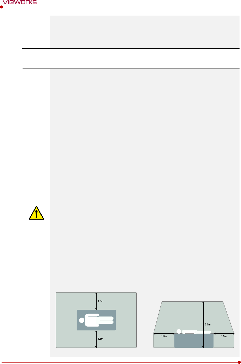
ALL pediatric patients shall be shielded for their X-ray examinations, except for when the shield will
obscure the region of interest, as in a pelvic or SI joint X-ray for trauma or arthritis, or when it is
physically or clinically unreasonable to shield the patient.
For routine Hip X-Rays, ALL male children shall have their scrotum shielded using the small gonadal
shield while females may not be shielded because doing so would obscure the hips.
To minimize motion in infants and young children, swaddle the infant. Use distraction tools to improve
cooperation and projectors with child-friendly themes, music, toys with flashing lights or music, child-
friendly images on the ceiling or walls, singing, counting, and a parent reading and talking to the child
through the console all can help reduce anxiety and comfort the child.
A scoliosis series will consist of a single frontal standing view of the spine. No lateral view or supine view
is needed, unless specifically asked for by the Orthopedist or Radiologist. If the female’s breasts can be
shielded without obscuring the spine, breast shields should be used.
1.5.8 Before Exposure
Be sure to check the equipment daily and confirm that it works properly.
Sudden heating of the room in cold areas will cause condensation to form on the equipment. In this
case, wait until the condensation evaporates before performing an exposure. If the equipment is used
while condensation is formed in it, problems may occur in the quality of captured images.
When an air-conditioner is used, be sure to raise/lower the temperature gradually so that difference
between the temperature in the room and in the equipment does not occur, to prevent condensation.
Rev.1.5
Page 19 of 121 D-16-207
VIVIX-S 1417N User Manual
1.5.9 During Exposure
This equipment is not protected (sealed) against liquids such as blood and medicine in the operating
room. If necessary, wrap the equipment in a disposable cover when using it.
Do not use the selected frequency channel (2.4 ㎓ and 5 ㎓ dual band) for other wireless devices.
Mutual interference may affect the image data transmission rate.
Do not use the detector near devices generating a strong magnetic field. Doing so may produce image
noise or artifacts.
1.5.10 Operating and Storage Environment
This equipment is mainly used in the X-ray exposure room and hospital wards. To use it in other places,
consult Vieworks’ sales representative or a distributor.
Do not expose this equipment to high temperatures and/or high humidity. Malfunctions may occur.
When not in use, keep the products in a safe location.
Be sure to use and store this equipment under the conditions described below.
Classification
Temperature
Humidity (Non-condensing)
Atmosphere
Operating Environment
+10 ~ +35℃
30 ~ 85%
700 ∼ 1060 hPa
Storage and Shipping
Environment
-15 ~ +55℃
10 ~ 90%
500 ∼ 1060 hPa
The operating environment of this equipment is complied with EN60721-3-3 Class 3K2.
The storage and shipping environment of this equipment is complied with EN60721-3-2
Class 2K2.
1.5.11 Others
Do not use this equipment in combination with peripherals such as defibrillators or large electric motors
as these may cause power-supply noise or power supply voltage variations. Doing so may prevent
normal operation of this equipment and peripherals.

Rev.1.5
Page 20 of 121 D-16-207
VIVIX-S 1417N User Manual
2. Product
This section gives an instruction about the product components and their specifications.
Product Components
VIVIX-S 1417N Detector
SCU Basic (FXRS-03A)
SCU mini (FXRS-04A)
SCU Lite (FXRP-02A)
Batttery Pack
Battery Charger
Others
Rev.1.5
Page 21 of 121 D-16-207
VIVIX-S 1417N User Manual
2.1 Product Components
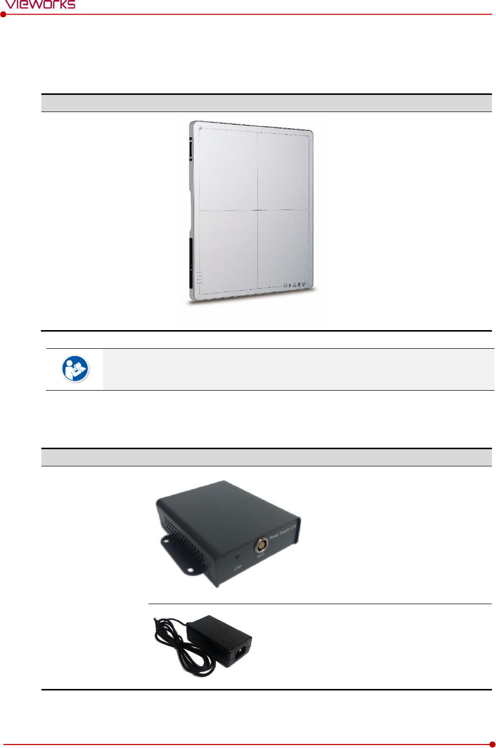
2.1.1 Detector
Product Name
Model / Description
VIVIX-S 1417N
Wireless Detector
FXRD-1417NAW (3.0kg)
FXRD-1417NBW (3.0kg)
A deco sheet attached on the detector can be different depending on each client
company.
2.1.2 SCU Lite (FXRP-02A)
Product Name
Model / Description
SCU Lite
FXRP-02A (330g)
DC Adaptor (BPM030S-24)
Rev.1.5
Page 22 of 121 D-16-207
VIVIX-S 1417N User Manual
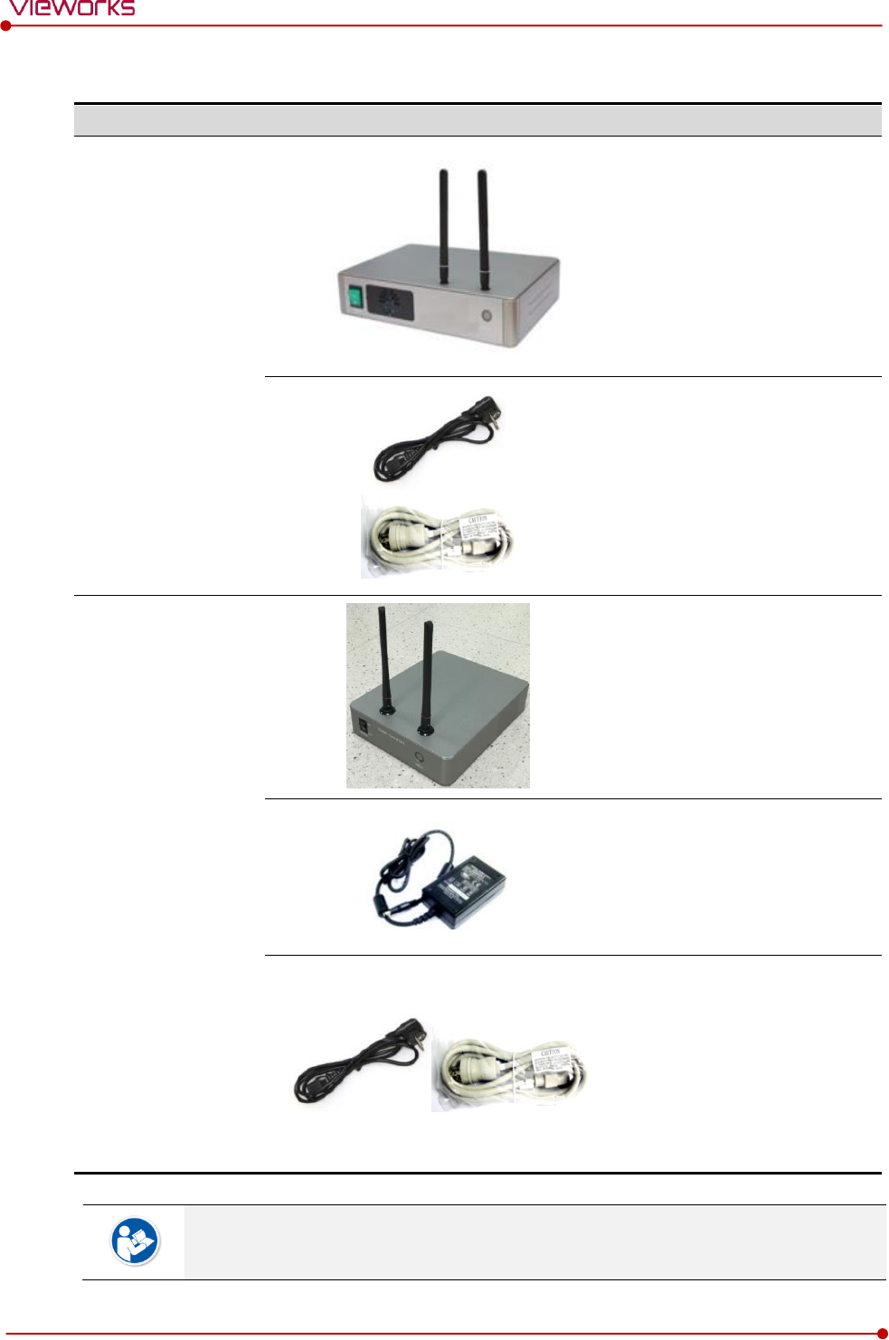
2.1.3 SCU (System Control Unit)
Component
Model / Description
SCU Basic
FXRS-03A (2.8kg)
AC Power Cable (2m)
110V (1EA) / 220V (1EA)
SCU mini
FXRS-04A (1.2kg)
DC Power Supply
(BPM060S24F10 / 24V)
AC Power Cable (2m)
110V (1EA) / 220V (1EA)
You can choose one of the SCU models depending on the purpose of use.
Rev.1.5
Page 23 of 121 D-16-207
VIVIX-S 1417N User Manual
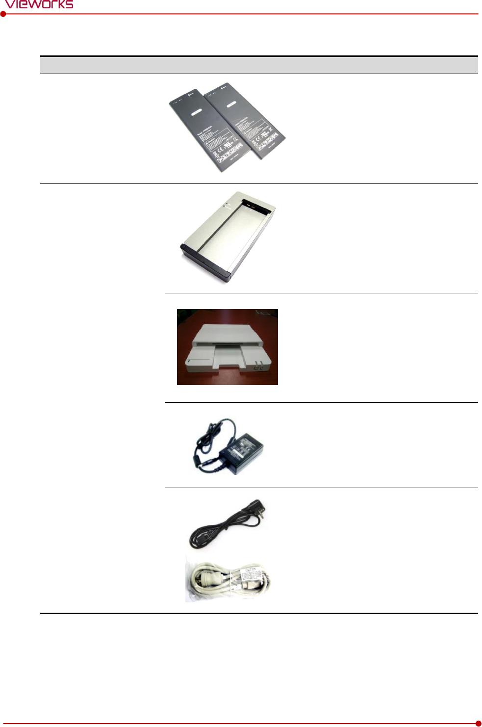
2.1.4 Battery & Charger
Component
Image
Model / Description
Battery
FXRB-03A (115g, 4EA)
Charger
FXRC-02A (0.8kg)
FXRC-03A (0.5kg, Option)
DC Power Supply (BPM060S24F10 / 24V)
AC Power Cable (2m)
110V (1EA) / 220V (1EA)
Rev.1.5
Page 24 of 121 D-16-207
VIVIX-S 1417N User Manual
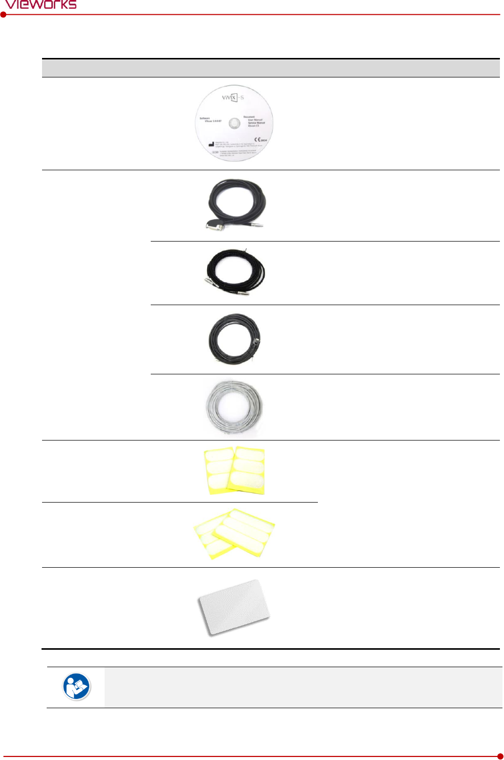
2.1.5 Accessories
Type
Image
Description
Resource
Software (Viewer or SDK)
Manuals
Cables
Tether Interface Cable (7m)
Ether Con Cable (7m, Option)
Generator Interface Cable (15m)
UTP LAN Cable (15m, Direct)
CAT 5E , CAT6 or higher
Velcro tape
(25mm x 50mm / 6ea)
Attached to the corners of bucky and
the friction surface of a detector.
Velcro tape
(25mm x 100mm / 6ea)
NFC card
Used to change settings of detector
through the NFC.
The design or the number of cards can be different depending on each client company.

Rev.1.5
Page 25 of 121 D-16-207
VIVIX-S 1417N User Manual
The use of accessories and cables other than those approved and sold by Vieworks Co.,
Ltd. may result in increased release of electromagnetic waves or decreased stability of the
equipment.
Accessory equipment connected to the analog and digital interfaces must be certified
according to the respective IEC standards. All combinations of equipment must be in
compliance with IEC 60601-1-1 system requirements.
Any person who connects additional equipment to the signal input or signal output ports
configures a medical system, and is therefore responsible for ensuring that the system
complies with the requirements of the system standard IEC 60601-1.
Consult your sales distributor or manufacturer if you have any concerns.

Rev.1.5
Page 26 of 121 D-16-207
VIVIX-S 1417N User Manual
2.2 VIVIX-S 1417N Detector
VIVIX-S 1417N is designed to acquire digital images by collecting x-ray signals and sereval conversion
processes. You can use the acquired image (14” x 17” film size) diversely depending on the purpose of use.
2.2.1 Specifications
Item
Specifications
Model
FXRD-1417NAW (CsI)
FXRD-1417NBW (Gadox)
Image Sensor
TFT: a-Si (Amorphous Silicon)
X-ray Scintillator Type
FXRD-1417NAW : Csl: TI (Thallium doped Caesuim Iodide)
FXRD-1417NBW : Gd2O2S:Tb (Gadolinium oxysulfide)
Pixel Pitch
0.14㎜ (140㎛)
Field of View
14” x 17”
Active Area (H x V)
358.4㎜ × 430.08㎜
Active Array
2560 x 3072 pixels
Effective Area
FXRD-1417NAW: 355.04㎜ x 426.72㎜
FXRD-1417NBW: 358.4㎜ × 430.08㎜
Effective Array
FXRD-1417NAW: 2536 x 3048 pixels
FXRD-1417NBW: 2560 x 3072 pixels
Grayscale
16bit
Spatial Resolution
Min. 3.5 lp/㎜
Image Acquisition Time (Wired)
1.5 sec.
Image Acquisition Time (Wireless)
3 sec.
Recommended Cycle Time
10 sec.
X-ray Synchronization Control
AED (Auto Exposure Detection)
DR Trigger (External line trigger)
Rated Power Supply
DC +24V, Max. 1.0A
Wired: Powered by SCU with a tether interface cable.
Wireless: Powered by a battery pack (3,100 ㎃h x 2)
Power Consumption
Max. 19.2 W
Operating Time
6 hours (Capturing), 8 hours (Standby) - when sleep mode is off
Dimensions (H × W × D)
384.0㎜ × 460.0㎜ × 15.0㎜
Weight
3.0 kg (Without a battery pack)
Image Transfer
Wired: Gigabit Ethernet (1000BASE-T) via PoE (Power over
Ethernet)
Wireless: IEEE 802.11n/ac (2.4GHz/5GHz)
Data Transmission Rate (Wired)
Max. 1Gbps
Data Transmission Rate (Wireless)
IEEE802.11n: Max. 450Mbps (MIMO 3X3)
IEEE802.11ac: Max. 1300Mbps (MIMO 3X3)
Rev.1.5
Page 27 of 121 D-16-207
VIVIX-S 1417N User Manual
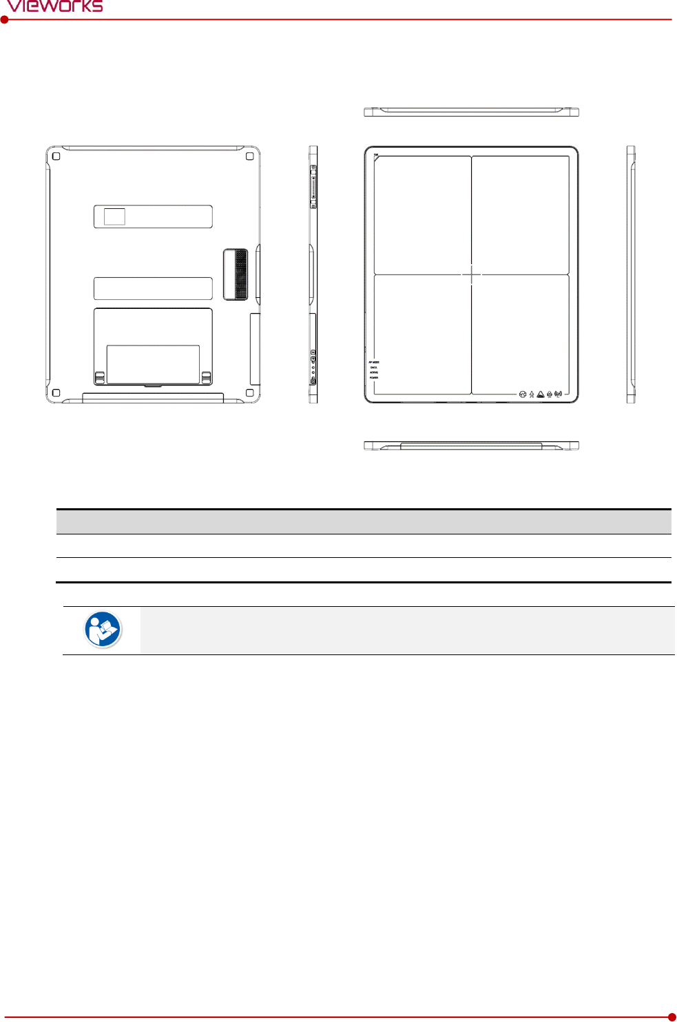
2.2.2 Drawing Sheet
Item
Description
Dimensions (H × W × D)
384.0㎜ × 460.0㎜ × 15.0㎜
Curvature of Edges
R15.0
The allowed tolerance of thickness of a detector is -2.0㎜ ~ +1.0㎜ under the ISO 4090
regulation.
Rev.1.5
Page 28 of 121 D-16-207
VIVIX-S 1417N User Manual
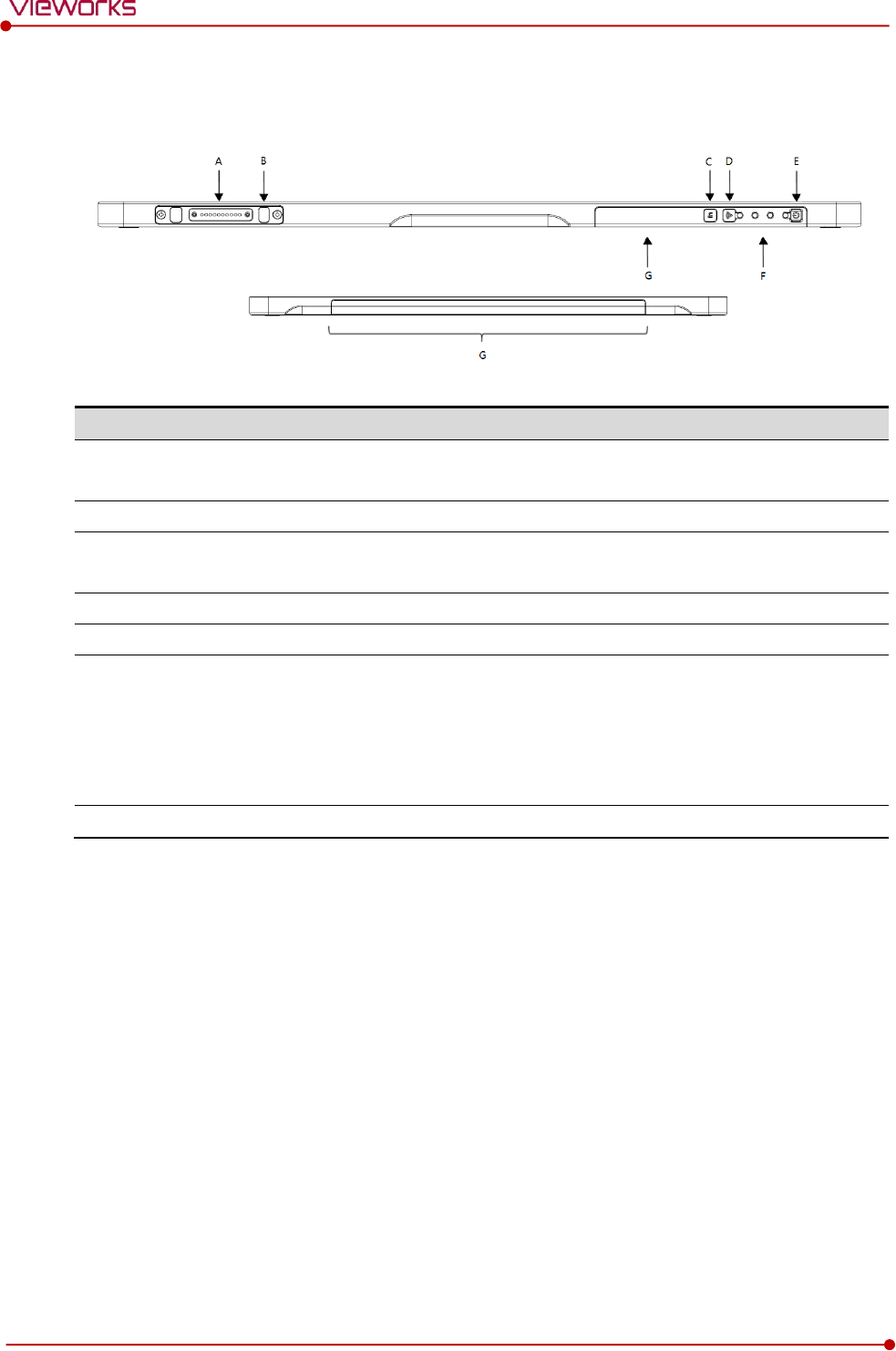
2.2.3 Functions
Side
Name
Description
A
Tether Interface Connector
Tightens the tether interface cable.
Used for wired connection between a detector and SCU.
B
Tether Interface Holder
Used for fixing and releasing a tether interface cable
C
Function Buttons
Checks the status of detector
Activates specialized functions
D
AP ON /OFF Button
AP ON/OFF Button : Turns on / off the AP mode
E
Power Button
Detector power button
F
Status LED
DATA LED (Blue) : Indicates data communication and
transmission status
ACTIVE LED (Orange) : Indicates readiness status to work
POWER LED (Green) : Indicates power On/Off status
AP Mode LED : Indicates On/Off status of AP mode
G
Antenna for Wireless LAN
Antennas for wireless communication (3EA)
Rev.1.5
Page 29 of 121 D-16-207
VIVIX-S 1417N User Manual
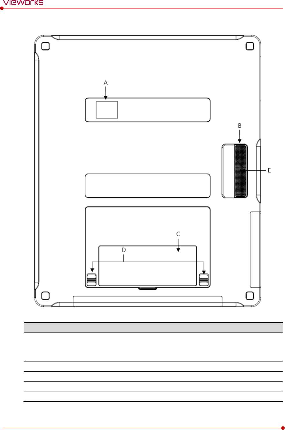
Rear
Name
Description
A
LED Display
Indicates battery remains
Indicates status of wireless connection and information
Indicates direction of the image
B
Handle
A handle for carrying a detector
C
NFC Contacts
Contacting part of the NFC tag
D
Lock Lever of the Battery Case
Locks/Unlocks the case of the attached battery pack.
E
Speaker
Sound output when contacting the NFC tag.
Rev.1.5
Page 30 of 121 D-16-207
VIVIX-S 1417N User Manual
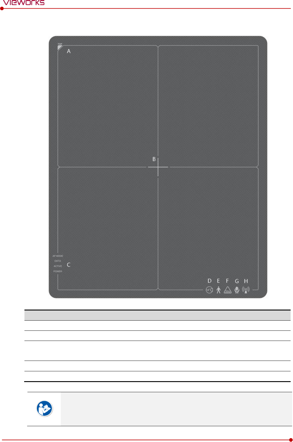
2.2.4 Deco Sheet
Indication Info.
Description
A
Image starting point
Indicates the starting point of an original image.
B
Center of the detector
Indicates the central position of detector.
C
Status indication logo
Indicates the operating state of detector.
AP Mode, DATA, ACTIVE, POWER
D-G
Certification logo
Indicates the certification logos relating to a medical device.
H
Wireless communication logo
Indicates that this model can be operated wirelessly.
Image starting point (0.0) of this detector is located nearby the tether interface connector.
You can change the displayed direction of an image from the VIVIX Setup program, but
it does not mean that the starting point and direction of the original image are changed.
E
Rev.1.5
Page 31 of 121 D-16-207
VIVIX-S 1417N User Manual
2.2.5 Wireless Communication
Item
Specifications
Wireless standard
IEEE 802.11n/ac
Frequency range
2.412 ~ 2.472㎓ (13 Channels)
5.18 ~ 5.24㎓ (4 Channels)
5.745 ~ 5.805G㎐ (4 Channels)
Data transmission rate
802.11n: Max. 450Mbps (MIMO 3X3)
802.11ac: Max. 1300Mbps (MIMO 3X3)
Modulation
BPSK, QPSK, 16-QAM, 64-QAM, 256-QAM
Transmission power
2.4㎓: Max. 19dBm (per chain)
5㎓: Max. 18dBm (per chain)
Security
WPA2-PSK
Antenna
Dual Band Antennas (3EA, In-built)
2.2.6 Use Environment
Item
Operation
Storage & Transportation
Temperature
+10 ~ +35℃
-15 ~ +55℃
Humidity
30 ~ 85% (Non-condensing)
10 ~ 90% (Non-condensing)
Atmospheric pressure
700 ~ 1060 hPa
500 ~ 1060 hPa
Shock
1.6G
20G
Vibration
0.7G
0.7G
The use environment of a detector and SCU is same.
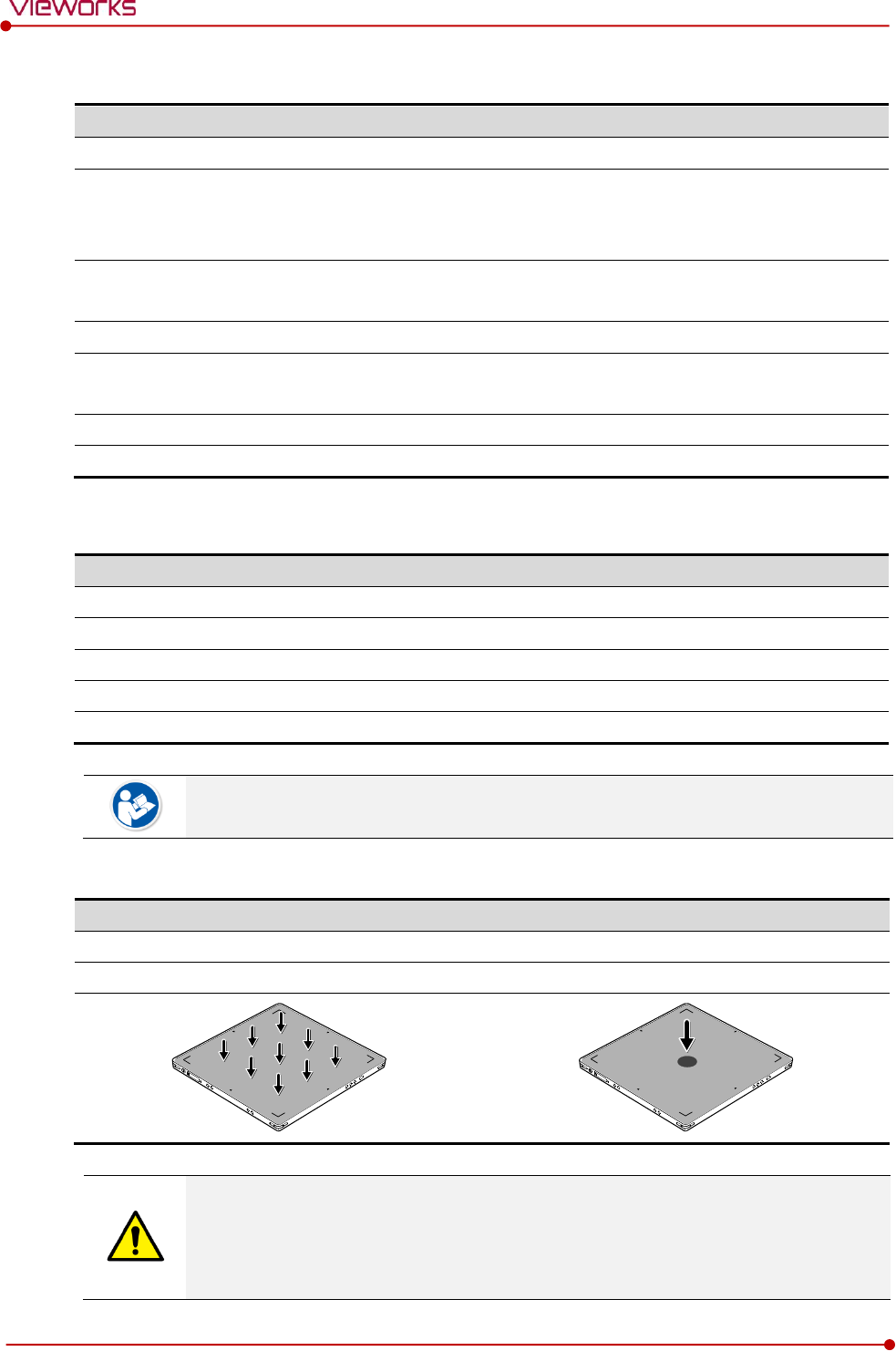
Load Limit of Detector
Uniform load
Local load
Over the whole surface
Center diameter 40 ㎜
Max. 300 kg
Max. 150 kg
Do not let the paitent or object heavier than load limit be on the detector. Then, detector
can be damaged.
Do not let the patient lie or get on the detector. Internal devices such as a sensor can be
seriously damaged even if his/her weight is within the load limit.
Rev.1.5
Page 32 of 121 D-16-207
VIVIX-S 1417N User Manual
2.3 SCU Basic (FXRS-03A)
SCU Basic synchronizes the image and X-ray signal as locating among the detector, workstation and the X-
ray generator. You can use the SCU Basic directly when the power supplies to SCU Basic after connecting it
under the VIVIX-S 1417N system environment
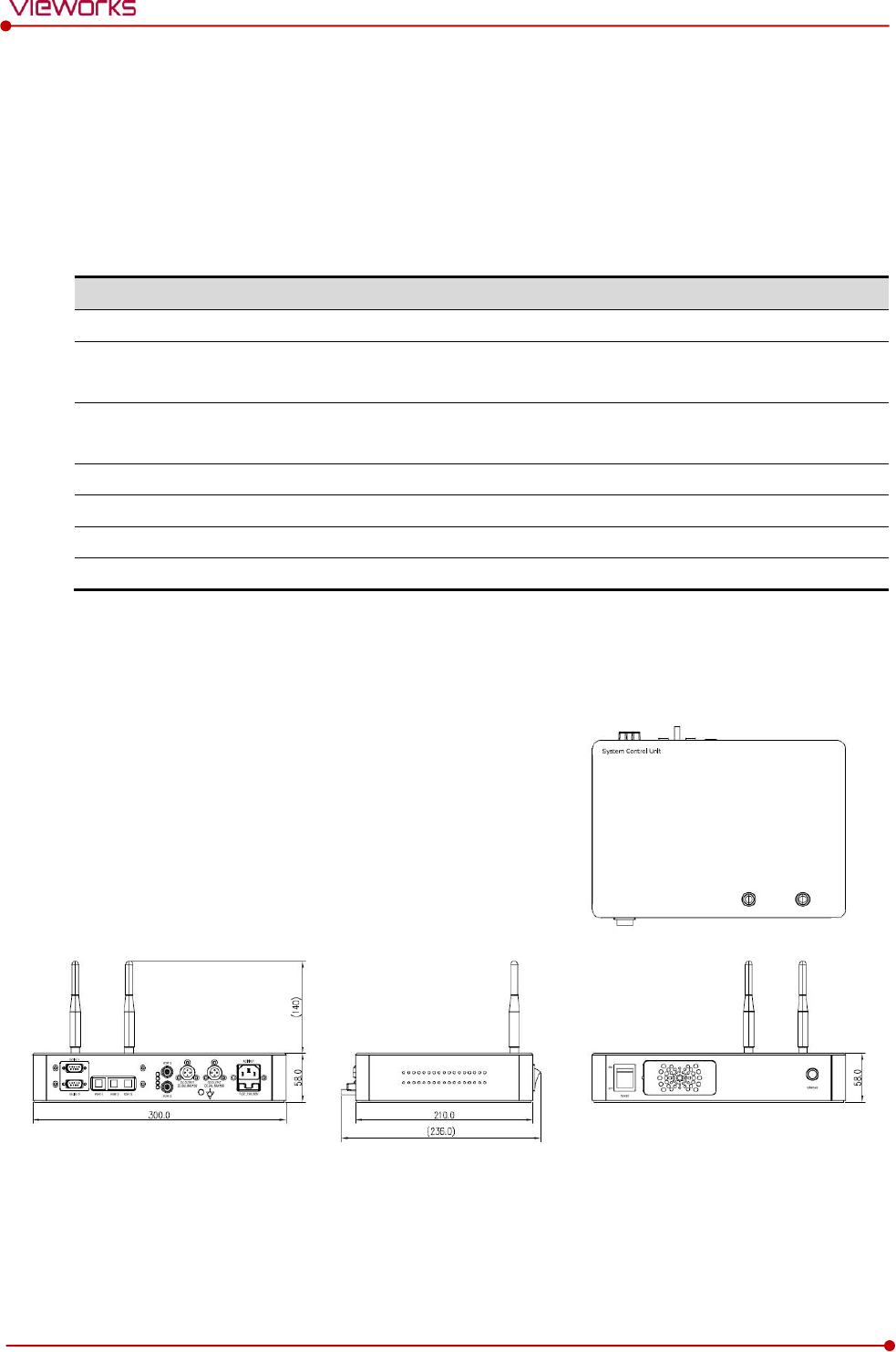
2.3.1 Specifications
Item
Specifications
Model
FXRS-03A
Power supply
Input: AC100 to 240V, 50/60㎐, Max. 2.0-0.8A
Output: DC +24V 3.25A, 78W
Cable connection port
Gigabit Ethernet port (3EA)
PoE (Power over Ethernet) Port (2EA)
Wireless communication
IEEE 802.11n (2.4 ㎓ / 5 ㎓)
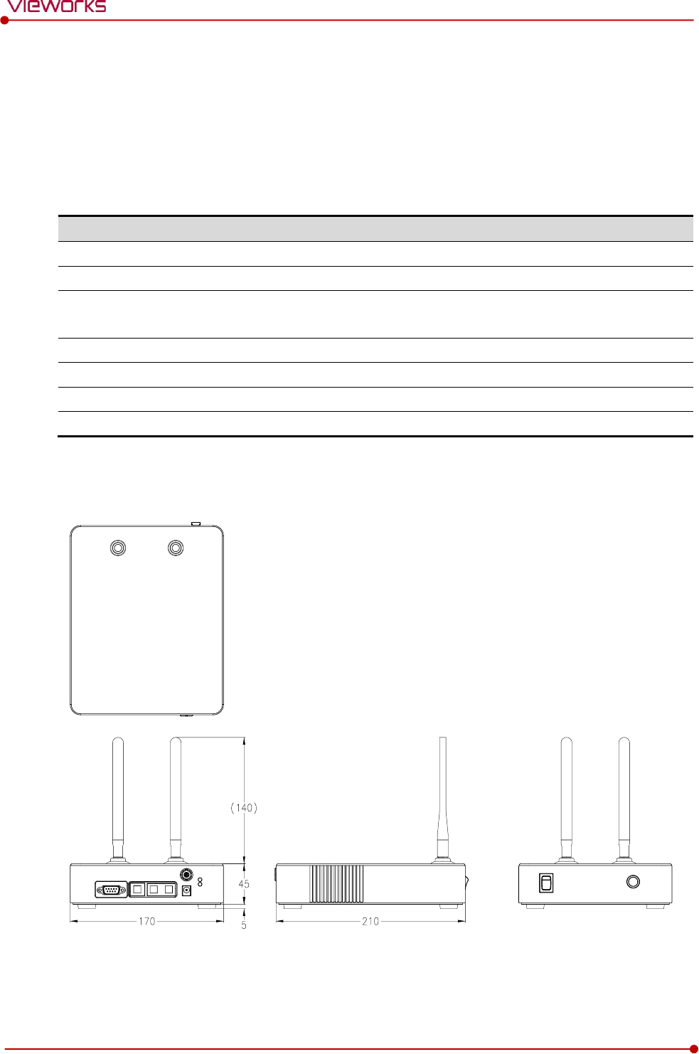
Dimension (H × W × D)
236.0 ㎜ × 300.0 ㎜ × 58.0 ㎜
Antenna
140 ㎜ (2EA, Dual band)
Weight
2.8 ㎏
2.3.2 Drawing Sheet
Rev.1.5
Page 33 of 121 D-16-207
VIVIX-S 1417N User Manual
2.3.3 Functions
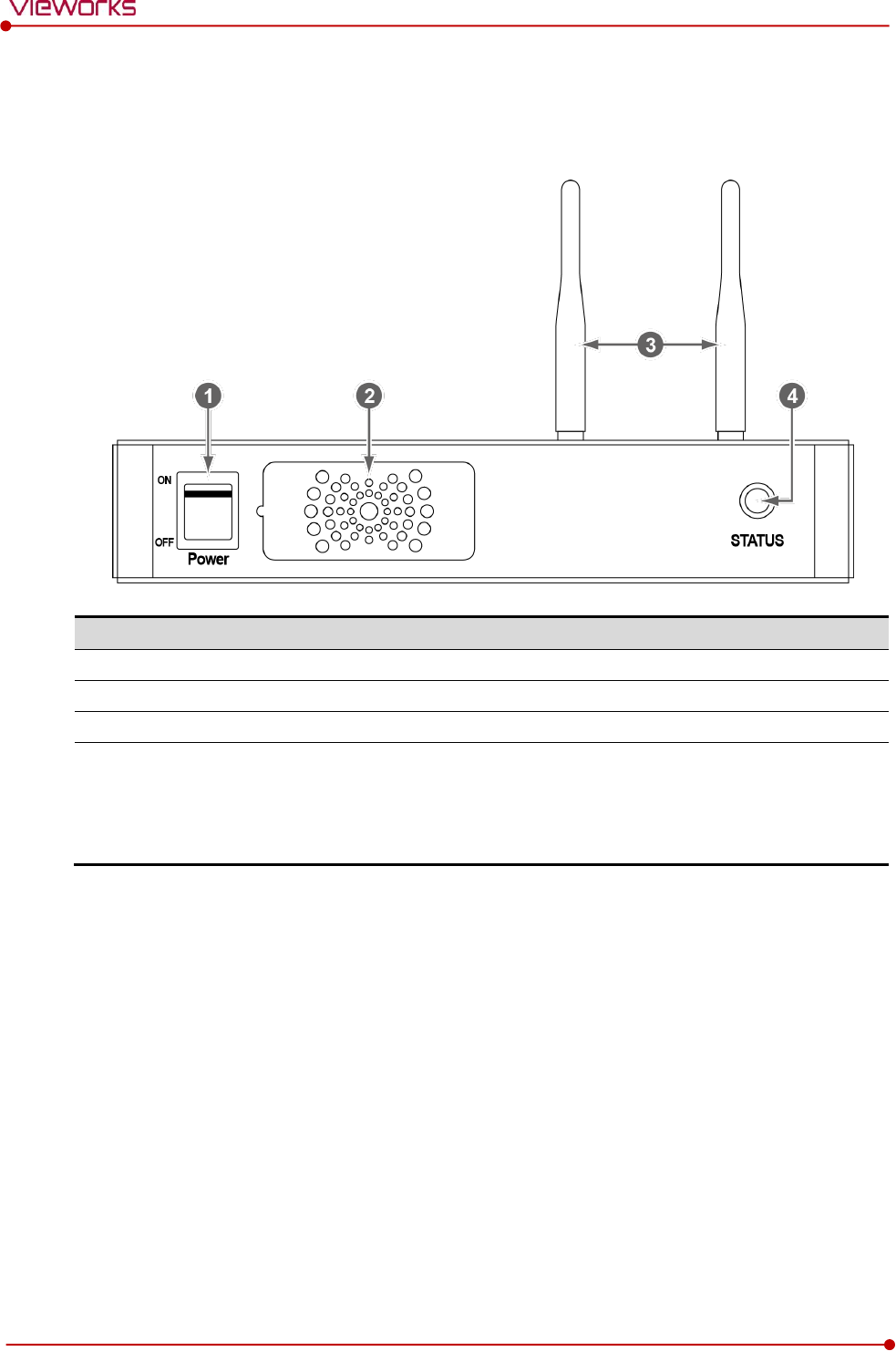
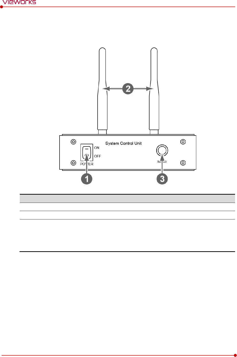
Front Side
No.
Name
Description
1
Power switch
Turns on/off the power of SCU Basic. (Including Green LED Lamp)
2
Fan
Expels the air which flows into the SCU Basic.
3
Antenna
Assists communications between the detector and SCU Basic.
4
Status LED
Indicates the operation and connection status of SCU Basic.
Blinking green: Booting
Green: Completed to boot up
Blue: The software is connected and ready to communicate.
Rev.1.5
Page 34 of 121 D-16-207
VIVIX-S 1417N User Manual
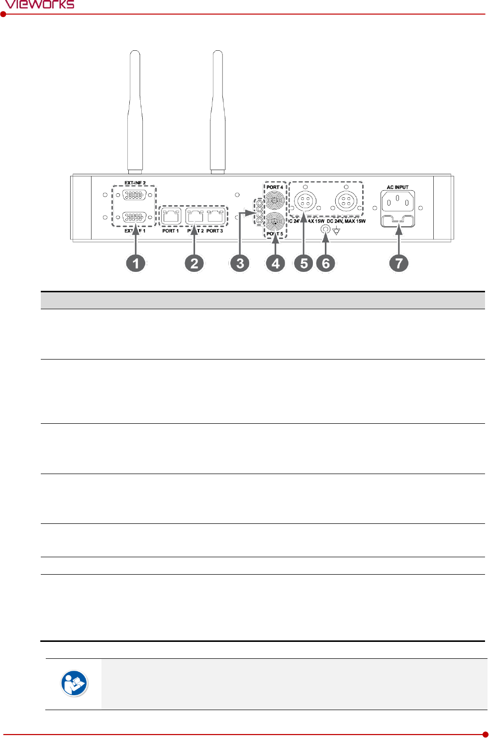
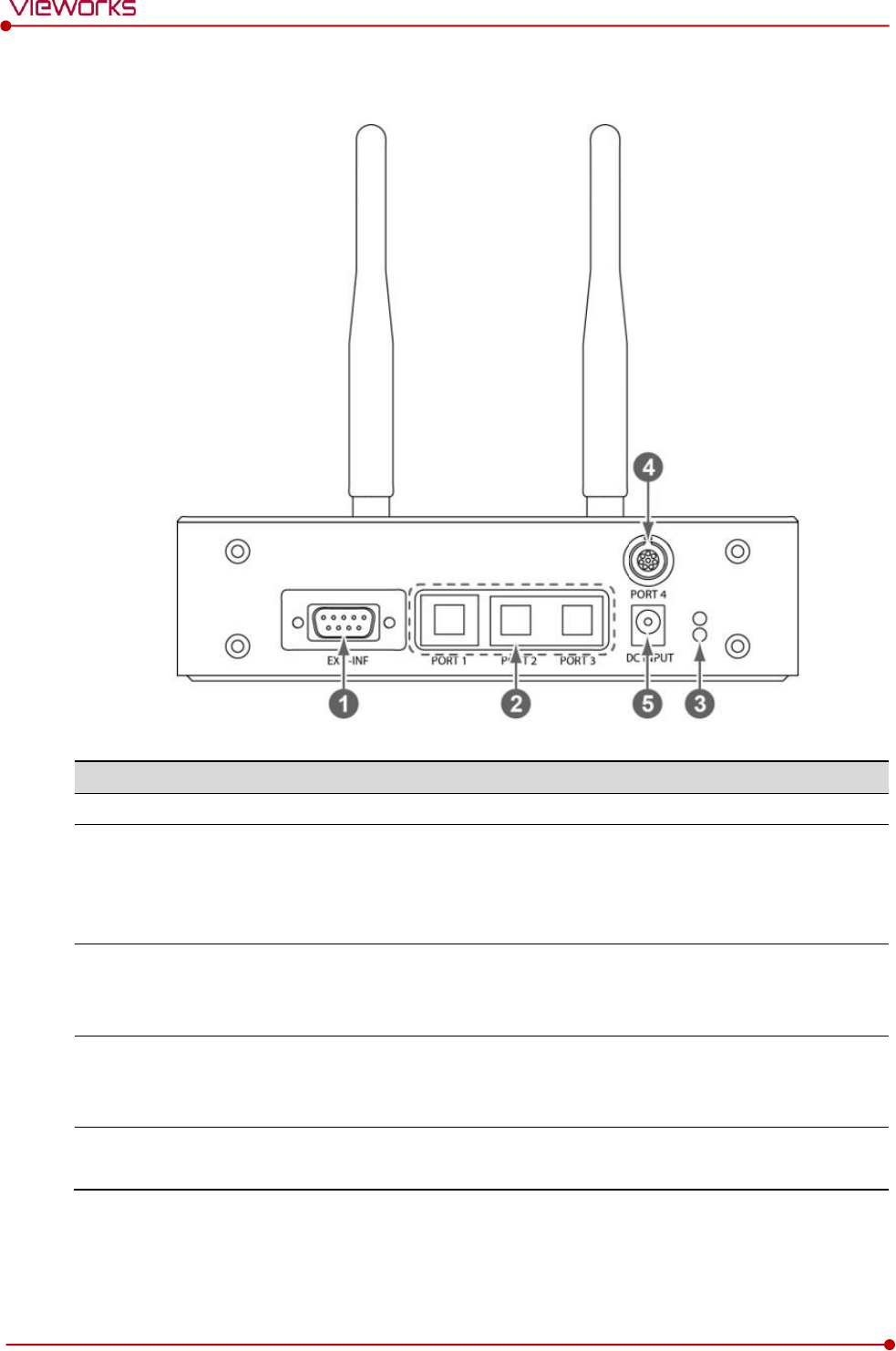
Rear Side
No.
Name
Description
1
EXT_INF1
EXT_INF2
X-ray generator interface connector (D-SUB 15 pins x 2 EA, Female)
EXT_INF1 : 1 ~ 15
EXT_INF2 : 16 ~ 30
2
LAN port
(Port 1, 2, 3)
Gigabit Ethernet port (1000BASE-T)
Port 1: Communicates between workstation and SCU Basic.
Port 2, 3: Communicates between FXRD-1717S detector and SCU
Basic when configuring multiple detectors.
3
PoE status lamp
Indicates the status of PoE port (Port 4, Port 5)
Green: 1 Gbps
Orange: 100 Mbps
4
PoE port
(Port 4, 5)
PoE (Power over Ethernet) port (1000BASE-T)
Communicates between the detector and SCU Basic.
Supplies power to the detector.
5
Detector power supply port
Max. DC +24V/15W (2 ports)
For FXRD-1717S detector only.
6
P.E
Equipotential ground
7
AC input port
T2AL250V fuse (2 EA)
100 ~ 240V
50/60㎐
Supplies power to SCU Basic.
The P.E (Potential Equalization) port of SCU is used to maintain potential equalization
between SCU and another grounded system. Use the conductor that can be detached
without the use of a tool.
Rev.1.5
Page 35 of 121 D-16-207
VIVIX-S 1417N User Manual
2.4 SCU mini (FXRS-04A)
SCU mini synchronizes the image and X-ray signal as locating among the detector, workstation and the X-
ray generator. You can use the SCU mini directly when the power supplies to SCU mini after connecting it
under the VIVIX-S 1417N system environment
2.4.1 Specifications
Item
Specifications
Model
FXRS-04A
Power supply
Input: DC +24V 2A Max
Cable connection port
Gigabit Ethernet port (3EA)
PoE (Power over Ethernet) Port (1EA)
Wireless communication
IEEE 802.11n (2.4 ㎓ / 5 ㎓)
Dimension (H × W × D)
210.0 ㎜ × 170.0 ㎜ × 45.0 ㎜
Antenna
140 ㎜ (2EA, Dual band)
Weight
1.2㎏
2.4.2 Drawing Sheet
Rev.1.5
Page 36 of 121 D-16-207
VIVIX-S 1417N User Manual
2.4.3 Functions
Front Side
No.
Name
Description
1
Power switch
Turns on/off the power of SCU mini.
2
Antenna
Assists communications between the detector and SCU mini.
3
Status LED
Indicates status of SCU mini operation and connection.
Blinking green: Booting
Green: Completed to boot up
Blue: The detector is connected and ready to communicate.
Rev.1.5
Page 37 of 121 D-16-207
VIVIX-S 1417N User Manual
Rear Side
No.
Name
Description
1
EXT_INF
X-ray generator interface connector (D-SUB 15pin, Female)
2
LAN port
(Port 1, 2, 3)
Gigabit Ethernet port (1000BASE-T)
Port 1: Communication between the workstation and SCU mini.
Port 2, 3: Communication between FXRD-1717S detector and SCU mini
when configuring multiple detectors.
3
PoE status lamp
Indicats the status of PoE port.
Green: 1 Gbps
Orange: 100 Mbps
4
PoE port
PoE (Power over Ethernet) port (1000BASE-T)
Communication between the detector and SCU mini.
Supplies power to the detector.
5
DC power input port
DC +24V
Supplies power to SCU mini.
Rev.1.5
Page 38 of 121 D-16-207
VIVIX-S 1417N User Manual
2.5 SCU Lite (FXRP-02A)
SCU Lite synchronizes the image and X-ray signal as locating between the detector and the workstation.
You can use the SCU Lite directly when the power supplies to SCU Lite after connecting it under the VIVIX-
1417N system environment.
2.5.1 Specifications
Item
Specifications
Model
FXRP-02A
Power supply
Input: DC +24V 1.0A Max.
Cable connection port
Gigabit Ethernet port (1EA)
PoE (Power over Ethernet) Port (1EA)
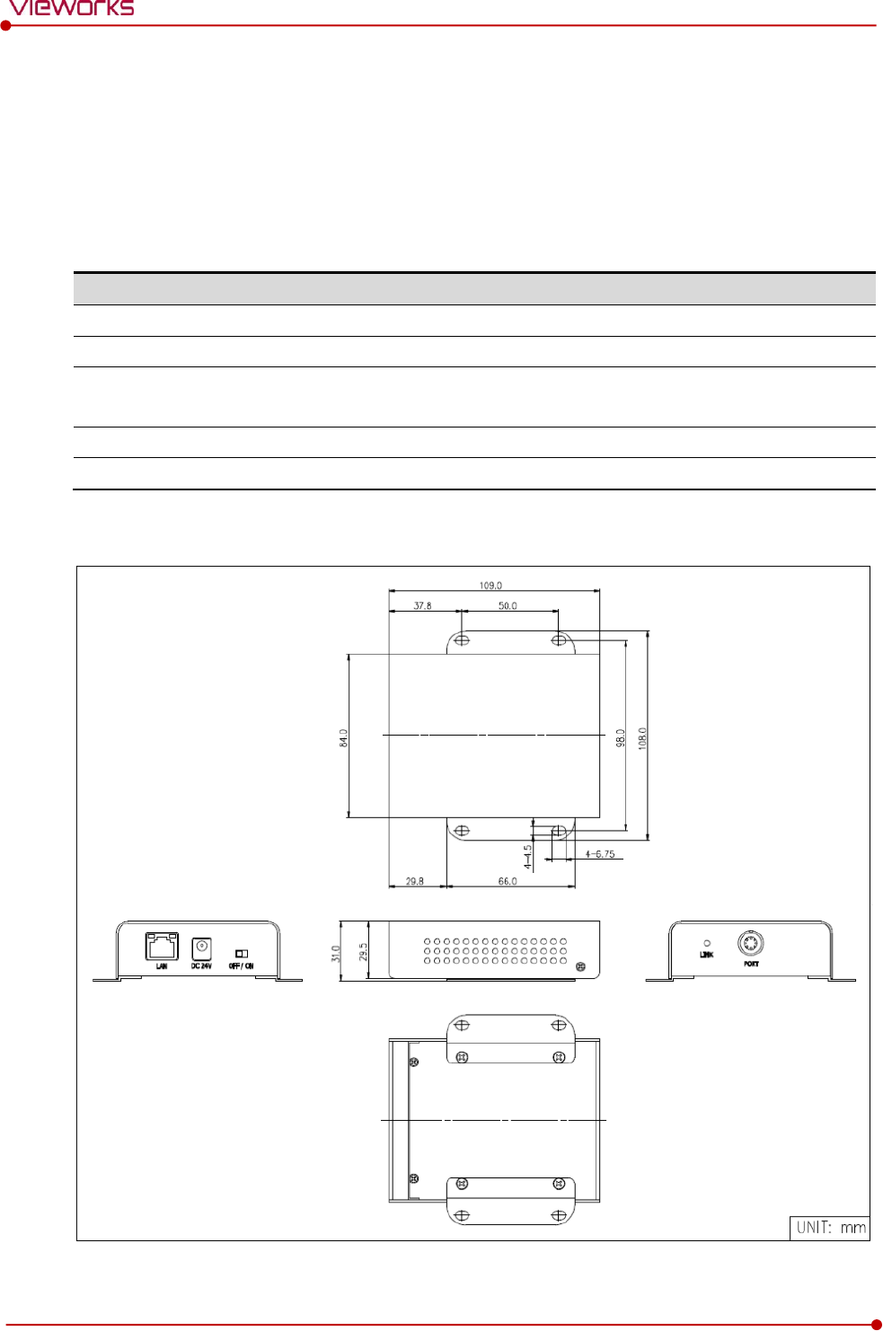
Dimension (H × W × D)
108 ㎜ × 109 ㎜ × 29.5 ㎜
Weight
330g
2.5.2 Drawing Sheet
Rev.1.5
Page 39 of 121 D-16-207
VIVIX-S 1417N User Manual
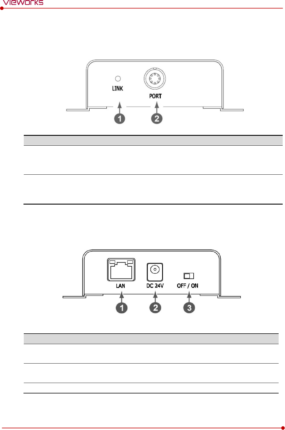
2.5.3 Functions
Front Side
No.
Name
Description
1
LINK LED
Indicates the status of PoE port.
Green : 1 Gbps
Yellow : 100 Mbps
2
POE Port
PoE (Power over Ethernet) port (1000BASE-T)
Communication between the detector and SCU Lite.
Supplies power to the detector.
Rear Side
No.
Name
Description
1
LAN port
Gigabit Ethernet port (1000BASE-T)
Communication between the workstation and SCU Lite.
2
DC power input port
DC +24V
Supplies power to SCU Lite.
3
Power Switch
Turns on/off the power of SCU Lite.
Rev.1.5
Page 40 of 121 D-16-207
VIVIX-S 1417N User Manual
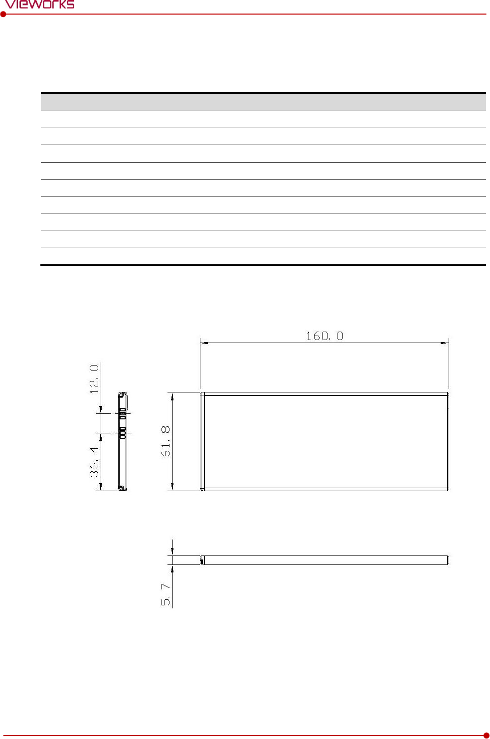
2.6 Battery Pack
2.6.1 Specifications
Item
Specifications
Model
FXRB-03A
Type
Lithium Ion
Rated Power Supply
Output: DC +7.6V
Capacity
3,100㎃h
Number of cell
2S1P (2 Series 1 Parallel)
Operation Time
3 hours (when sleep mode is off)
Cycle Life
Approx. 500 times (Fully charged/Discharged completely, 1cycle)
Dimension (H × W × D)
160.0 ㎜ × 61.8 ㎜ × 5.7 ㎜
Weight
115g
2.6.2 Drawing Sheet
Rev.1.5
Page 41 of 121 D-16-207
VIVIX-S 1417N User Manual
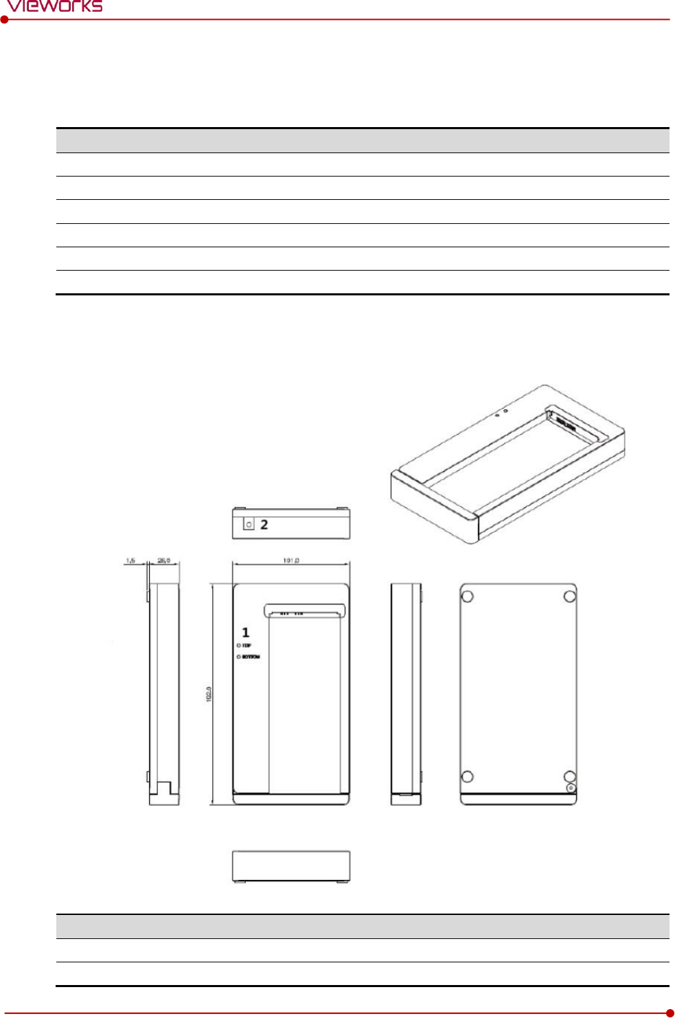
2.7 Battery Charger (FXRC-02A)
2.7.1 Specifications
Item
Specifications
Model
FXRC-02A
Simultaneous Charging
2 battery packs
Charging time
2 1/2 hours
Rated power supply
DC +24V, 2A Max.
Dimension (H × W × D)
192.0㎜ × 101.0㎜ × 26.0㎜
Weight
0.8 ㎏
2.7.2 Drawing Sheet
No.
Name
Description
1
Top / Bottom LED
Indicates the location and status of a battery pack being charged.
2
Power input port
Supplies electric power by connecting a power adapter to the charger.
Rev.1.5
Page 42 of 121 D-16-207
VIVIX-S 1417N User Manual
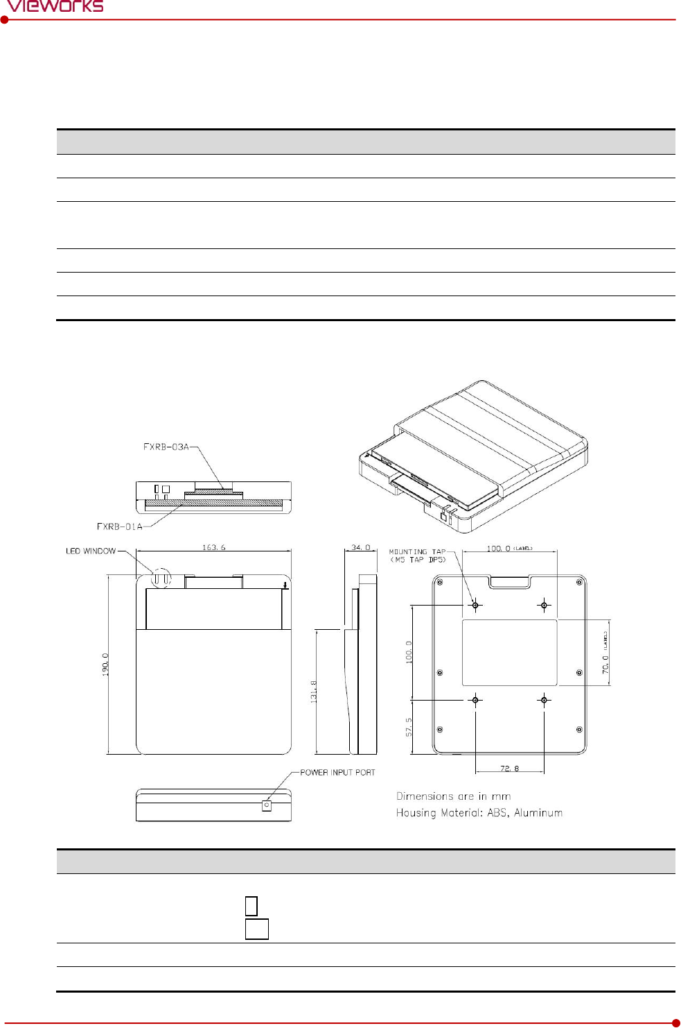
2.8 Battery Charger (FXRC-03A)
2.8.1 Specifications
Item
Specifications
Model
FXRC-03A
Simultaneous Charging
2 battery packs (FXRB-01A (1ea) / FXRB-03A (1ea))
Charging time
FXRB-01A: 3 hours
FXRB-03A: 2 1/2 hours
Rated power supply
DC +24V, 2A Max.
Dimension (H × W × D)
163.6 ㎜ × 190 ㎜ × 34.0 ㎜
Weight
0.5 ㎏
2.8.2 Drawing Sheet
No.
Name
Description
1
LED Window
Indicates the location and status of a battery pack being charged.
: FXRB-03A
: FXRB-01A
2
Power input port
Supplies electric power by connecting a power adapter to the charger.
3
Mounting hall
Screw holes for fixing the charger to the external device. (M5 x 8)
1
2
3
Rev.1.5
Page 43 of 121 D-16-207
VIVIX-S 1417N User Manual
2.9 Others
2.9.1 X-ray Generator (Recommended Exposure Condition)
Item
Recommended condition
X-ray energy range
40kVp ~ 150kVp
Reliability (Lifetime Dose)
100Gy
2.9.2 Recommended Specifications of Workstation (PC)
Item
Recommended specification
Operating System
VIVIX Setup
Microsoft Windows 7 (32bit / 64bit)
Microsoft Windows 7 64bit SP1 (Professional Edition or higher)
Microsoft Windows Vista Service pack 1 or higher (32bit / 64bit)
Microsoft Windows 8 (32bit / 64bit) / 8.1 64bit SP1 (Professional
Edition or higher
Microsoft Windows 10 (32bit / 64bit)
CPU
Intel Core i5 2600 or higher (or compatible CPU)
Memory
4GB or higher
Hard Disk
1TB or higher
LAN Card (only for
detector communication)
Gigabit (for detector only)
Intel® PRO 1000 Series (Gigabit LAN Card for network interface)
Min.requiremetns
Speed: 1Gbps or more
Jumbo Frames: 9K
Receive Descriptors: 2K (1024 or higher)
Monitor
1024 x 768 or more
CD-ROM
CD or DVD R/W
2.9.3 Recommended Specifications of Grid
Item
Recommended specification
SID
100cm / 130cm / 150cm / 180cm
Ratio
8.1 / 10:1 / 12:1
Frequency
215 line/inch
Check the recommended specifications by Vieworks first before buying the generator,
workstation and grid.

Rev.1.5
Page 44 of 121 D-16-207
VIVIX-S 1417N User Manual
3. System Configuration
This section gives information about the various connection / configuration ways among the
detector, SCU, workstaton and X-ray generator.
You can figure out the most suitable way of system configuration through this instruction.
Detector Connection Methods
Diagram
System Configuration
Generator Interface
Configuring DR Trigger Interface
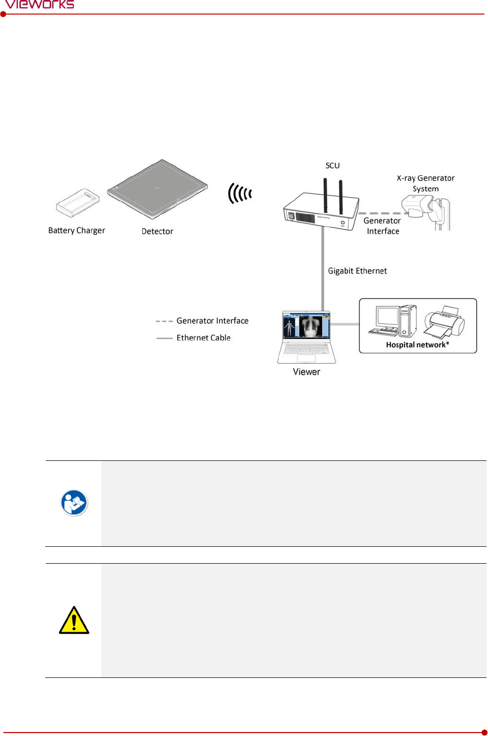
Rev.1.5
Page 45 of 121 D-16-207
VIVIX-S 1417N User Manual
3.1 Detector Connection Methods
You can organize wired or wireless connection between the VIVIX-S 1417N detector and SCU. You can
also choose other connection ways suitable for the use environment in case of need.
3.1.1 Wireless Connection
The images and data are transmitted between the VIVIX-S 1417N detector and SCU by wireless
connection.
A battry pack should be installed in the detector to use it under the wireless configuration.
We recommend you to use the wireless connection method for the following cases.
When using the unfixed detector.
When the wired communication is in trouble by the interruption of cables.
The wireless connection is more freely to operate than the wired connection.
Use the wireless connection with a laptop computer to enhance mobility.
Be sure to operate the wireless commnunication between the detector and SCU within a
maximum of 8m.
Use of multiple WLAN devices within the same frequency band may interfere with each
wireless communication and cause a decline in transmission speed.
Do not cover or block the wireless module of the detector. Also, do not put any shielding
materials between the detector and SCU. Otherwise, the transmission speed or operable
distance may be reduced.
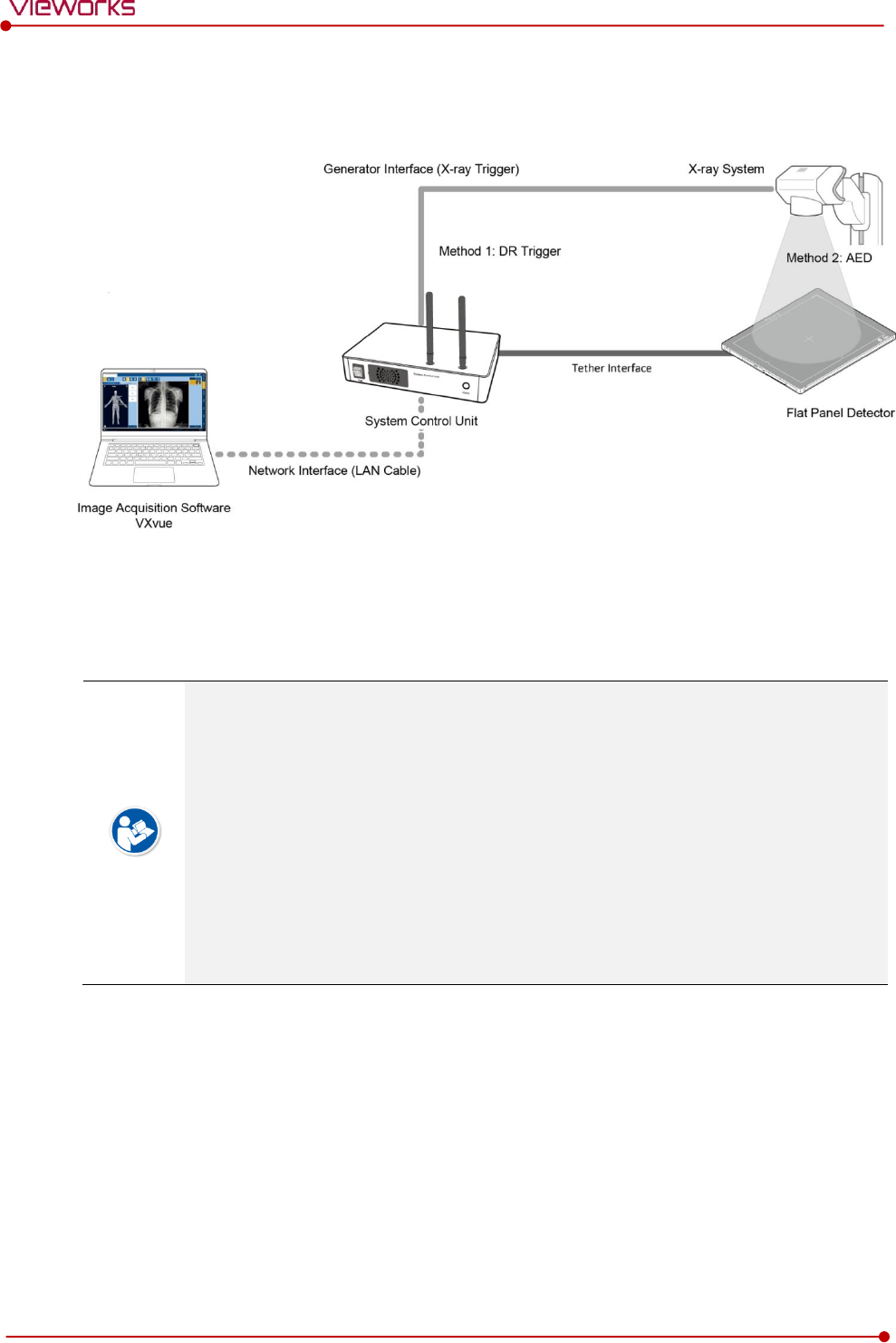
Rev.1.5
Page 46 of 121 D-16-207
VIVIX-S 1417N User Manual
3.1.2 Wired Connection
Connect VIVIX-S 1417N detector and SCU with a tether interface cable to make a wired configuration.
As the tether interface cable supplies power to the detector, a battery pack is not needed to be
installed in the detector.
We recommend you the wired connection method for the following cases.
When continuous power supply to the detector is needed.
When the detector is fixed in a bucky stand or on a table.
When you upgrade the detector firmware or change the inner configural information.
When you need the data communication to be faster than the wireless connection.
A battery pack in the detector is kept charging under the wired connection.
When two batteries are installed in the detector, one battery is fully charged first and
the remaining battery is charged continuously.
The wireless communication module of the detector maintains its inactivation status
under the wired connection.
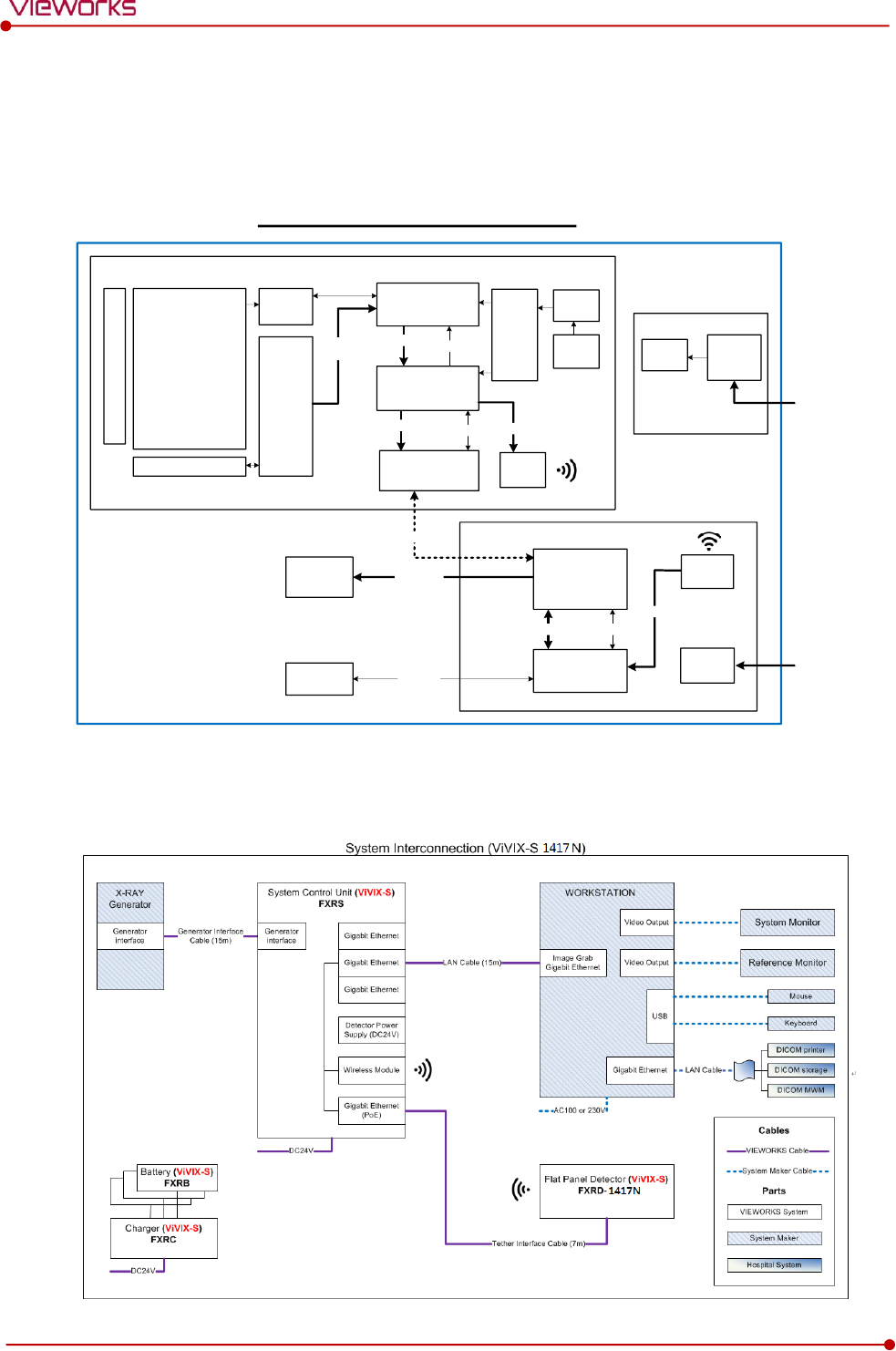
Rev.1.5
Page 47 of 121 D-16-207
VIVIX-S 1417N User Manual
3.2 Diagram
3.2.1 Block Diagram
3.2.2 Wiring Diagram
VIVIX-S 1417N Block Diagram
Battery
Gigabit Ethernet
PHY
DETECTOR
FPGA (TG)
Network Processor
Auto
Exposure
Trigger
ADC
ROIC
GATE B/D
WLAN
Module
Control
Image
Data
A-Si TFT Matrix
with PIN Diode
2560 x 3072
Data
Data Control
Power
Converter
Data
Charger
Controller
Charger
Data (PoE)
PC Image Data
Generator
I/F
X-ray
Generator
Gigabit Ethernet
Switch
Network
Processor
SCU
DC INPUT
+24V
DC-DC
Converter
Data Control
WLAN
Module
Data
Battery
Charger Battery
DC INPUT
+24V
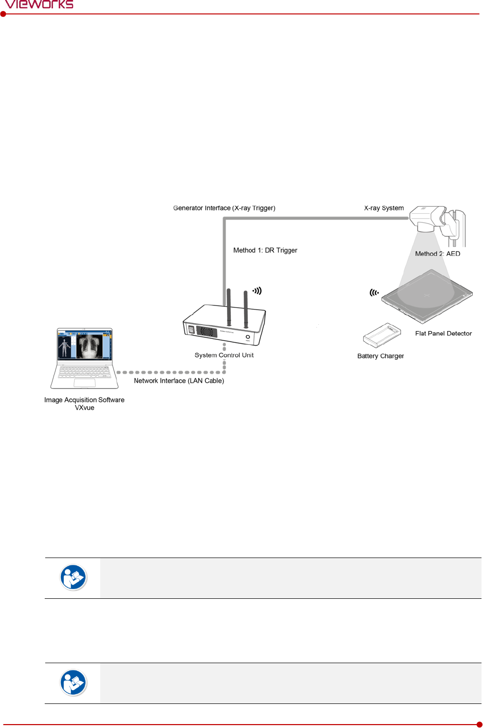
Rev.1.5
Page 48 of 121 D-16-207
VIVIX-S 1417N User Manual
3.3 System Configuration
This section gives information about the configuration modes of VIVIX-S 1417N detector, SCU, workstation
and the generator.
3.3.1 AP Mode (SCU AP Mode)
SCU AP mode is the wireless connection method that connecting the detector with SCU as the center
wirelessly. If the device is connected on AP mode, Wi-fi function is turned on. Wireless function is turned
off if the device is connected on Tether Interface Mode as it is a wired connection mode.
SCU & Detector
The VIVIX-S 1417N detector and SCU are connected wirelessly. In this case, SCU and the detector
operate as AP (Access Point) and STATION respectively.
SCU & PC (Workstation)
SCU and PC (Workstation) are connected with the LAN cable.
It is available to connect SCU and PC wirelessly. In this case, SCU and the detector
operate as AP (Access Point) and STATION respectively.
SCU & Generator
SCU and the generator can be connected with the generator interface cable.
It is unnecessary to connect SCU and the generator with a generator interface cable if
you use AED mode of the detector.
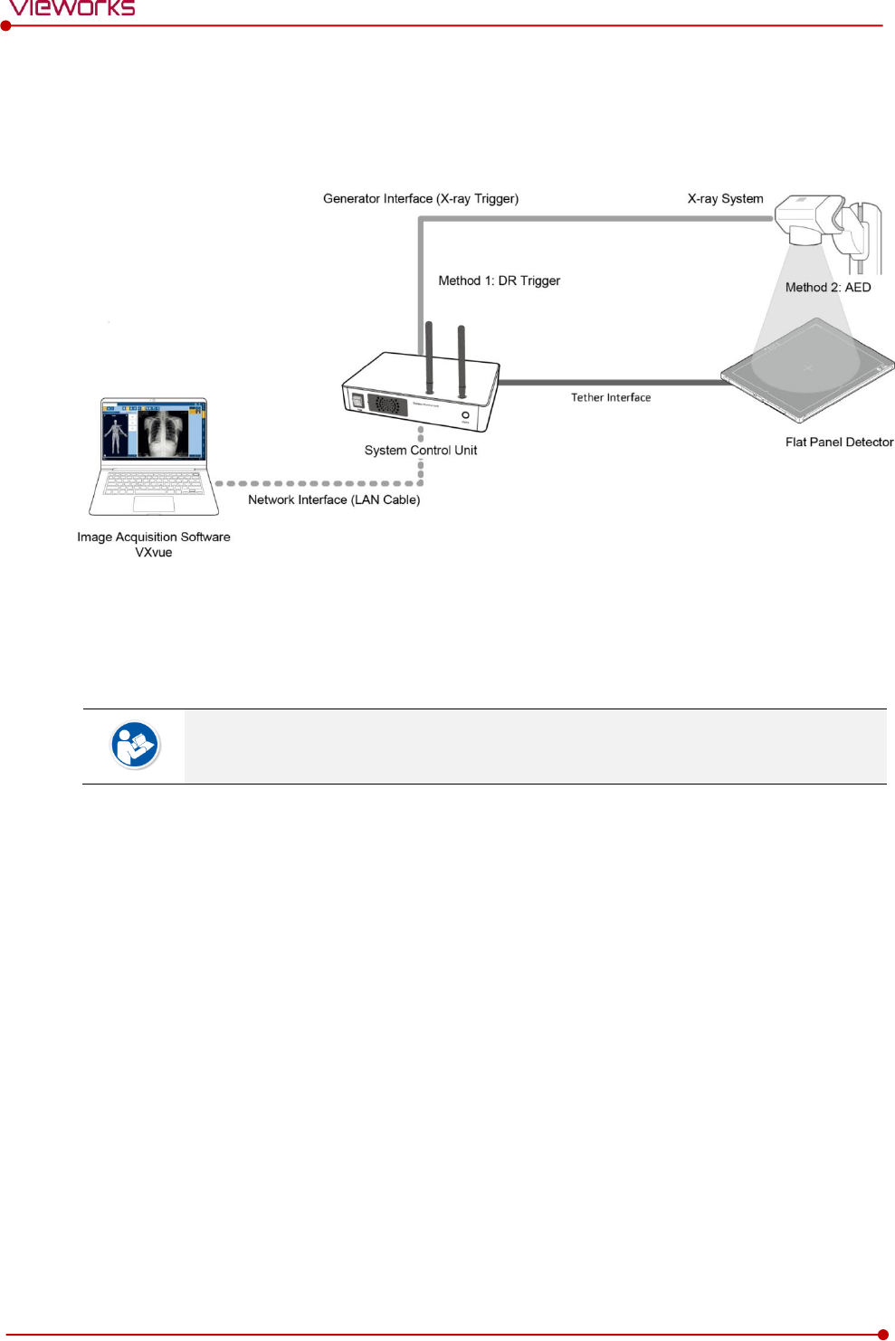
Rev.1.5
Page 49 of 121 D-16-207
VIVIX-S 1417N User Manual
3.3.2 Tether Interface Mode
Tether interface mode is the wired connection method that connecting the detector with SCU as the center.
SCU & Detector
SCU and the VIVIX-S 1417N detector are connected with the tether interface cable.
Other connection ways of the tether interface mode are the same as the AP mode.
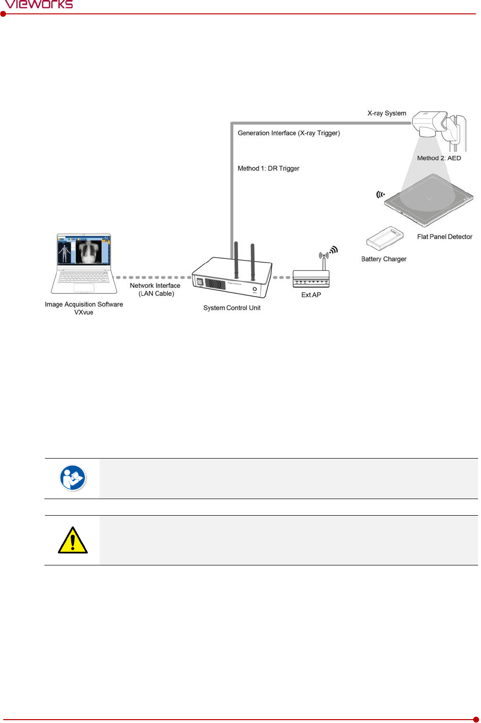
Rev.1.5
Page 50 of 121 D-16-207
VIVIX-S 1417N User Manual
3.3.3 External AP Mode
External AP mode is the wireless connection method that adding the external AP device instead of SCU.
External AP & SCU
The external AP and SCU are connected with a LAN cable.
External AP & Detector
The external AP and VIVIX-S 1417N detector are connected wirelessly. In this case, the external AP and
the detector operate as AP (Access Point) and STATION respectively.
Other connection ways of the tether interface mode are the same as the AP mode.
Be sure to check the specifications of external AP device when configuring the external
AP mode, since the wireless communication performance can be different by the
specifications.
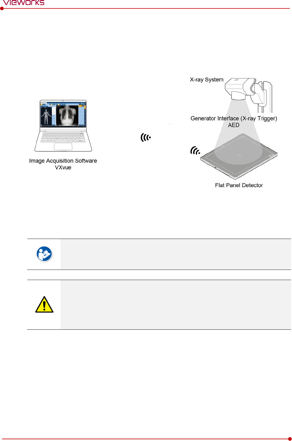
Rev.1.5
Page 51 of 121 D-16-207
VIVIX-S 1417N User Manual
3.3.4 Detector AP Mode
Detector AP mode is the wireless connection method that connecting the PC (Workstation) with the
detector as the center wirelessly.
Detector & PC (Workstation)
The VIVIX-S 1417N detector and PC are connected wirelessly. In this case, the detector and the PC
operate as AP (Access Point) and STATION respectively.
Since SCU is not used for configuring the detector AP mode, you can only use the AED
mode without a wired connection. (Cannot use the DR Trigger mode.)
This mode can be used when mobility and portability are needed.
When configuring the detector AP mode, be sure to check the specifications of wireless
module installed in the PC. The wireless communication performance can be different
depending on the specifications of the wireless module.
If the wireless connection cannot be made normally because of unexpected problems,
SCU can be needed to check the detector condition.
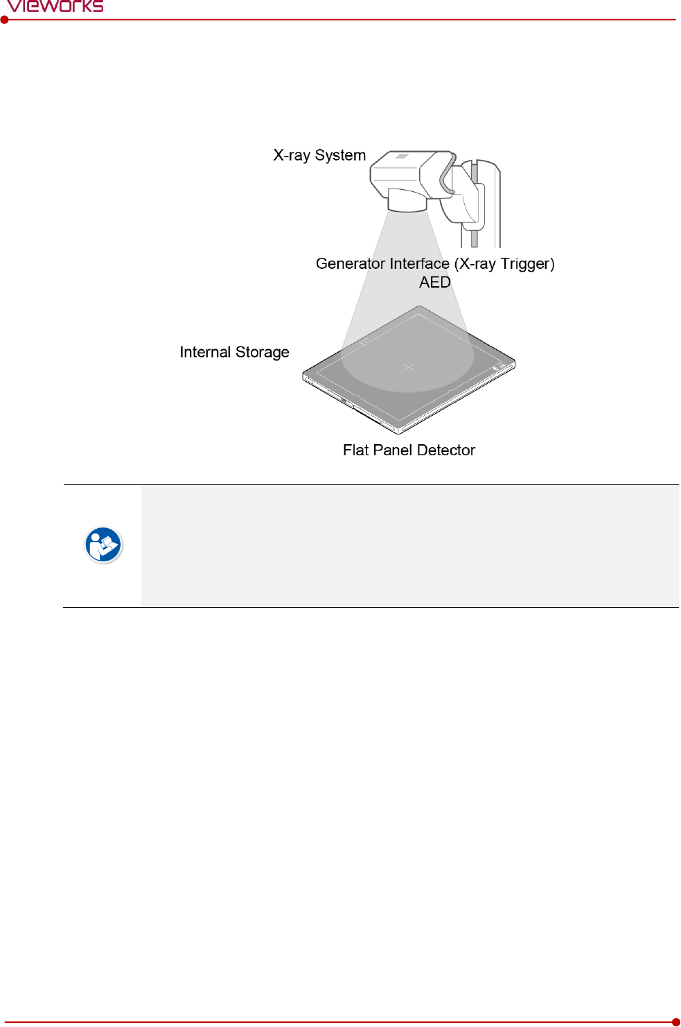
Rev.1.5
Page 52 of 121 D-16-207
VIVIX-S 1417N User Manual
3.3.5 Detector Stand-Alone Mode
You can use the Stand-Alone mode without making a wired or wireless connection.
You should take images with the AED mode only when using the Stand-Alone mode.
(Cannot use the DR Trigger mode.)
The acquired images are stored in the internal storage of the detector in order and the
images can be transmitted to the PC after connecting the detector to the PC.
The transmitted images are removed automatically from the detector.
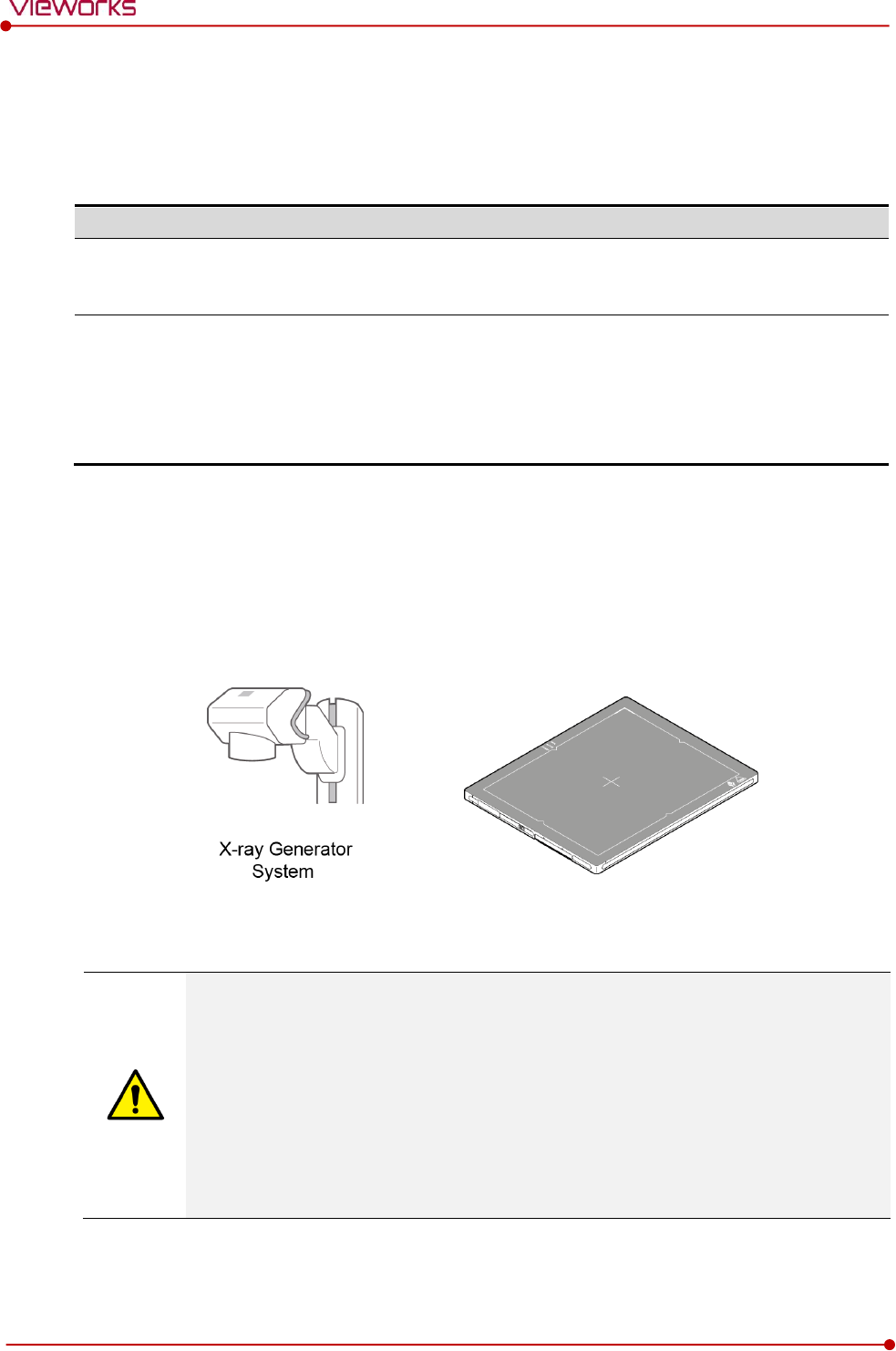
Rev.1.5
Page 53 of 121 D-16-207
VIVIX-S 1417N User Manual
3.4 Generator Interface
VIVIX-S 1417N detector provides AED and DR Trigger intertace as a generator interface way to acquire
images by detecting X-ray.
Mode
Description
AED
The detector detects X-ray exposure from the generator automatically and then performs
image acquisition without any cable connection.
DR Trigger
The detector and generator receive and send their signal to each other for image
acquisition.
SCU and X-ray generator should be connected with the generator interface cable.
DR Trigger interface is not supported in case you connect SCU Lite FXRP-02A) with
the X-ray generator.
3.4.1 AED (Auto Exposure Detection) Interface
If the VIVIX-S 1417N detector is used as the AED interface, you can acquire images without connecting the
generator to the detector with a generator interface cable.
Cautions when using AED interface
Make sure to follow the operating environmental condition (Temp: +10℃ ~ +35℃).
Do not give impact to the product. If it receives strong jolt, unwanted images may be
acquired without the X-ray exposure because of the malfunction of the AED sensor.
You may not acquire images or horizontal artifacts may occur depending on the external
environment such as exposure condition, thickness of object or the use of grid.
When you set X-ray exposure area to the direction of the detector, the center of the
detector should be involved in the X-ray exposure area. Otherwise, you may not acquire
an image.
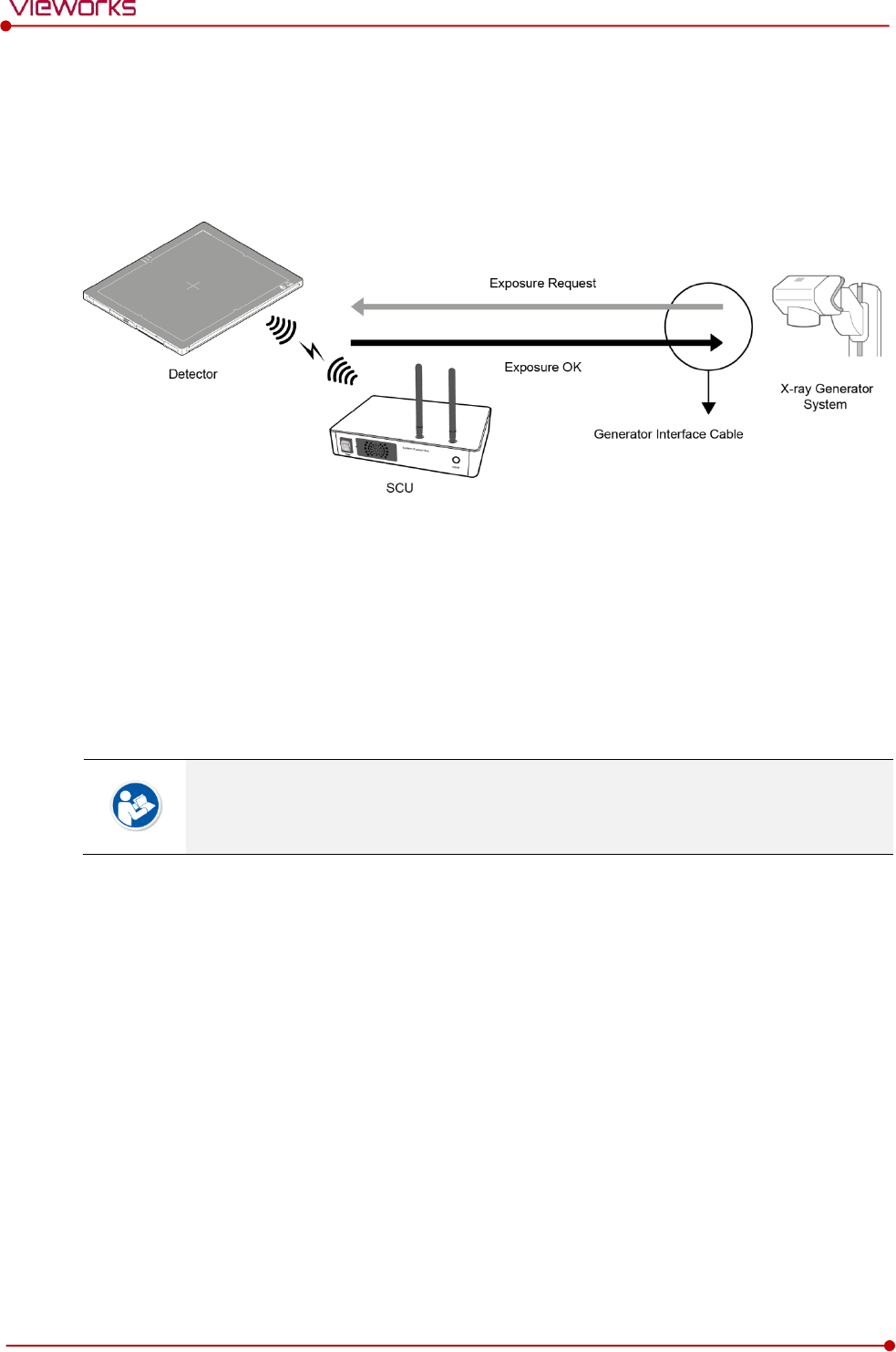
Rev.1.5
Page 54 of 121 D-16-207
VIVIX-S 1417N User Manual
3.4.2 DR Trigger Interface
Connect the detector and X-ray generator with a generator interface cable, and then acquire images by
sending and receiving their signal.
Signal Processing Steps
1 The detector receives EXP_REQ signal from the X-ray generator.
2 After the detector completes to prepare image acquisition, it sends the EXP_OK signal to the X-ray
generator.
3 The X-ray generator confirms EXP_OK signal and generates X-rays.
4 The detector acquires images and then transmits the image data.
EXP_REQ is a sending signal from X-ray generator to the detector for requesting
exposure.
EXP_OK is an exposure ready signal from the detector to X-ray generator.
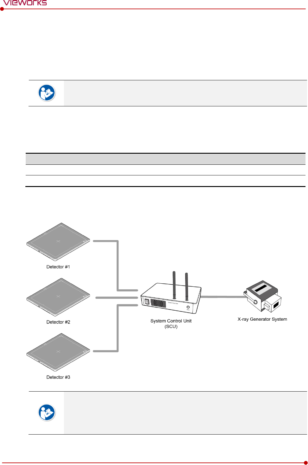
Rev.1.5
Page 55 of 121 D-16-207
VIVIX-S 1417N User Manual
3.5 Configuring DR Trigger Interface
To configure the DR Trigger interface, SCU and the generator should be connected with a generator
interface cable. Connect the one end of generator interface cable to EXT_INF port of SCU, and then
connect the other end to the generator.
Up to three generators can be connected with SCU Basic.
Only a single generator can be connected with SCU mini.
3.5.1 Trigger Interface Way
The generator interface cable is connected differently depending on the trigger interface ways.
Trigger Interface
Description
Packet Trigger
Handles exposure signal by exchanging packet.
Line Trigger
Handles exposure signal by exchanging electrical signal.
3.5.2 Packet Trigger
Multipe detectors share one generator signal together.
Connect a generator interface cable to one of the pin groups.
The generator tramsmits and receives signal with the one selected detector for taking
images.

Rev.1.5
Page 56 of 121 D-16-207
VIVIX-S 1417N User Manual
3.5.3 Line Trigger
Each detector shares a signal signal by being connected with generators separately.
Up to three X-ray generators can be connected to SCU.
The connection of each detector and generator can be configured from VIVIX Setup.
You should comprehend about a detector and X-ray generator to make correct exposure.
Otherwise, X-ray can be exposed to the detector in different location.
The engineer who understand the generator device and interface technology should be in
charge of interface work between SCU and the generator.
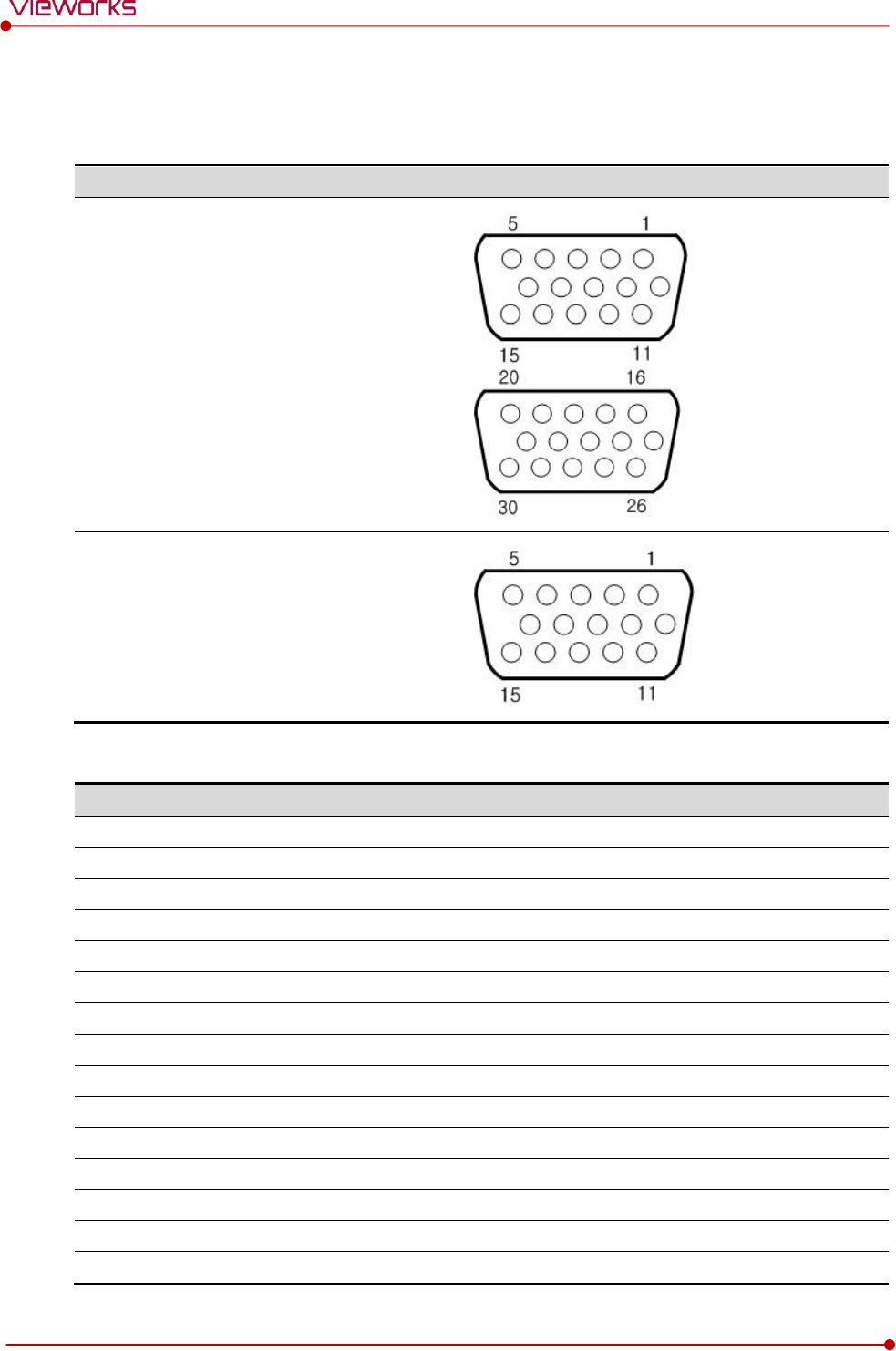
Rev.1.5
Page 57 of 121 D-16-207
VIVIX-S 1417N User Manual
3.5.4 EXT_INF Port Pin Map
EXT_INF port is D-SUB 15 pin female connectors of SCU, and used for the generator interface.
Product
EXT_INF port
SCU Basic (FXRS-03A)
SCU mini (FXRS-04A)
EXT_INF1 port pin map definition (1 ~ 15)
No.
Signal name
I/O
Type
Color
Ch.
Description
1
EXP_REQ+_A
Input
Contact
Red
A
Receives EXP_REQ
2
EXP_REQ-_A
Input
Contact
Black
A
Returns signal from EXP_REQ+_A
3
EXP_REQ_TTL_A
Input
TTL
Orange
A
Receives EXP_REQ
4
EXP_REQ_GND_A
Input
TTL
Gray
A
Returns signal from EXP_REQ_TTL_A
5
EXP_OK_POWER_A/B
Input
-
Yellow
A/B
Power of TTL signal
6
EXP_OK+_A
Output
-
Green
A
Sends EXP_OK
7
EXP_OK-_A
Output
-
Brown
A
Returns signal from EXP_OK+_A
8
EXP_OK+_B
Output
-
Blue
B
Sends EXP_OK
9
EXP_OK-_B
Output
-
Pink
B
Returns signal from EXP_OK+_B
10
Reserved
-
-
-
-
Reserved for test only.
11
EXP_REQ+_B
Input
Contact
White
B
Receives EXP_REQ
12
EXP_REQ-_B
Input
Contact
Purple
B
Returns signal from EXP_REQ+_B
13
EXP_REQ_TTL_B
Input
TTL
White/Red
B
Receives EXP_REQ
14
EXP_REQ_GND_B
Input
TTL
White/Black
B
Returns signal from EXP_REQ_TTL_B
15
Reserved
-
-
-
-
Reserved for test only.
Rev.1.5
Page 58 of 121 D-16-207
VIVIX-S 1417N User Manual
EXT_INF2 port pin map definition (16 ~ 30)
No.
Signal name
I/O
Type
Color
Ch.
Description
16
EXP_REQ+_C
Input
Contact
Red
C
Receives EXP_REQ
17
EXP_REQ-_C
Input
Contact
Black
C
Returns signal from EXP_REQ+_C
18
EXP_REQ_TTL_C
Input
TTL
Orange
C
Receives EXP_REQ
19
EXP_REQ_GND_C
Input
TTL
Gray
C
Returns signal from EXP_REQ_TTL_C
20
EXP_OK_POWER_C
Input
-
Yellow
C
Power of TTL signal
21
EXP_OK+_C
Output
-
Green
C
Sends EXP_OK signal
22
EXP_OK-_C
Output
-
Brown
C
Returns signal from EXP_OK+_C
23
EXT_W+
Input
Contact
-
-
User-defined Pin 1
24
EXT_W-
Input
Contact
-
-
Returns signal from EXT_W+
25
EXT_X+
Input
Contact
-
-
User-defined Pin 2
26
EXT_X-
Input
Contact
-
-
Returns signal from EXT_X+
27
EXT_Y+
Input
Contact
-
-
User-defined Pin 3
28
EXT_Y-
Input
Contact
-
-
Returns signal from EXT_Y
29
EXT_Z+
Input
Contact
-
-
User-defined Pin 4
30
EXT_Z-
Input
Contact
-
-
Returns signal from EXT_Z+
Since SCU mini has the EXT_INF 1 port only, one generator can be connected with it.
Up to three X-ray generators can be connected to EXT_INF1 and EXT_INF2 ports, and
each generator should be connected with a same channel.
There are Contact type (OPEN/ CLOSE) and TTL type (ON/ OFF) on the signal in/output
pin.
TTL type information
ON : VCC
OFF : GND
Current: 5 ㎃ ~ 10 ㎃
Voltage: 12 V ~ 24 V
When you plan to add interface using a user-defined pin, contact to the person in charge
of Vieworks.
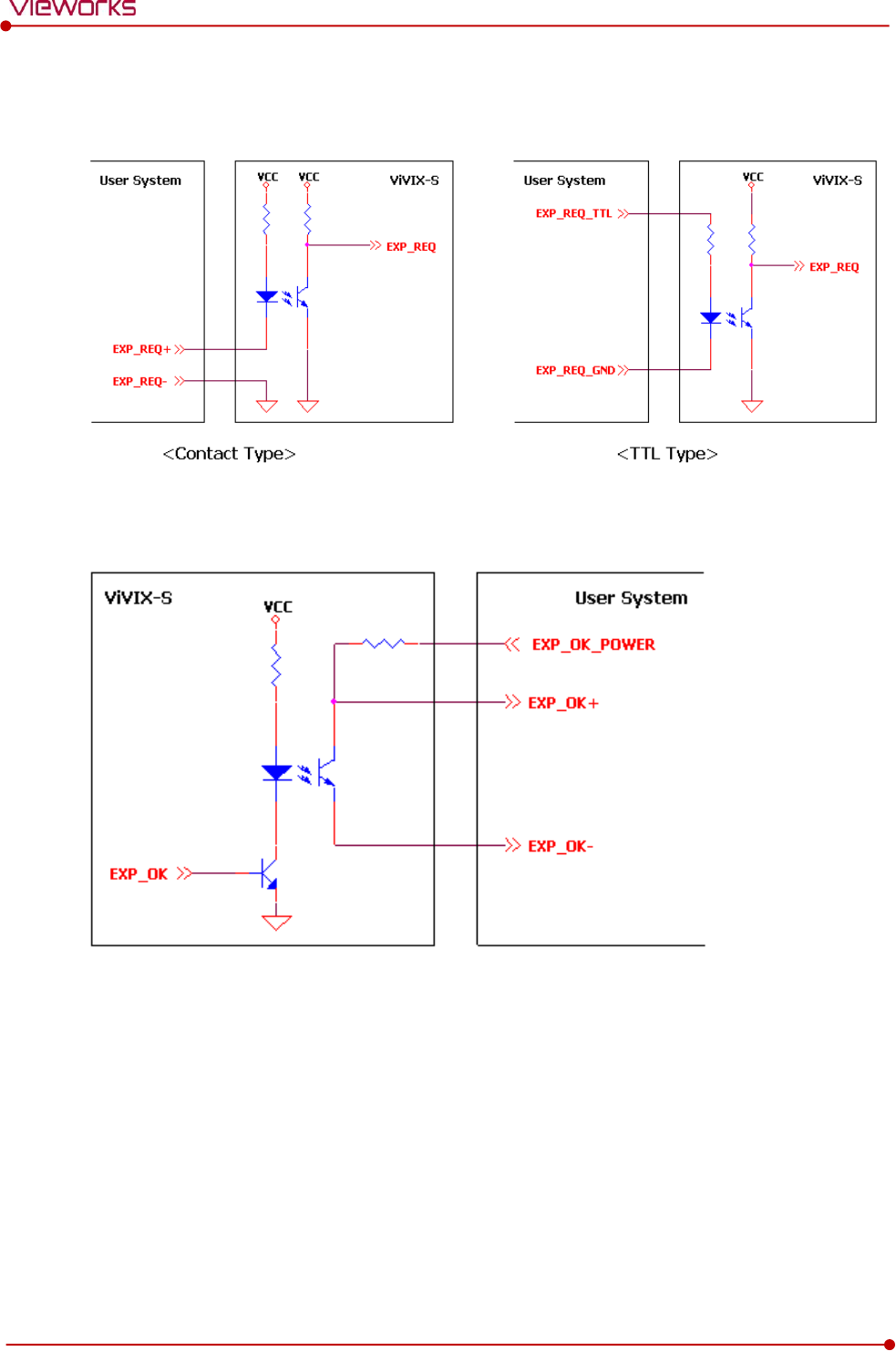
Rev.1.5
Page 59 of 121 D-16-207
VIVIX-S 1417N User Manual
3.5.5 Input / Output Circuit
Exposure Request Input Circuit (EXP_REQ)
Exposure Respond Output Circuit (EXP_OK)

Rev.1.5
Page 60 of 121 D-16-207
VIVIX-S 1417N User Manual
4. Settings
This section gives information about the way of installation, setting, and diagnosis to use a
detector with SCU.
Battery Pack
Product Installation
Device Setting
Diagnosis of Devices
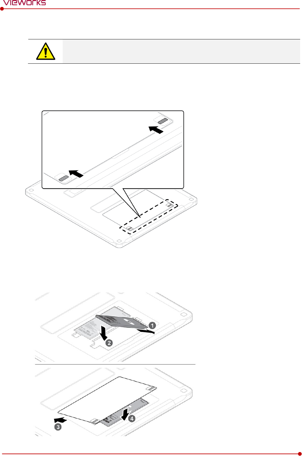
Rev.1.5
Page 61 of 121 D-16-207
VIVIX-S 1417N User Manual
4.1 Battery Pack
Detector and its attached devices should be installed by an authorized service engineer.
If you encounter any problems, consult the sales representative or engineer in Vieworks.
4.1.1 How to Insert Battery Packs
1 Raise the two lock/unlock levers of a battery case.
2 Open the battery cover.
3 Insert a battery pack and close the battery cover.
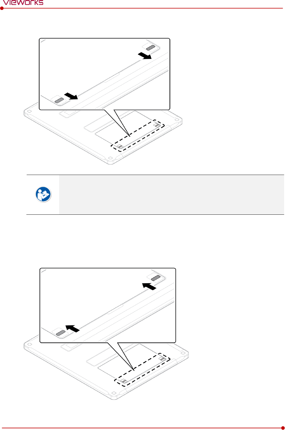
Rev.1.5
Page 62 of 121 D-16-207
VIVIX-S 1417N User Manual
4 Pull down the two lock/unlock levers of a battery case.
Check if the battery is fully charged before using.
Make sure that the battery pack is securely inserted.
The remaining battery can be checked from the battery lamp on the side of detector or
from the VIVIX Setup program.
4.1.2 How to take out a battery pack
1 Raise the two lock/unlock levers of a battery case.
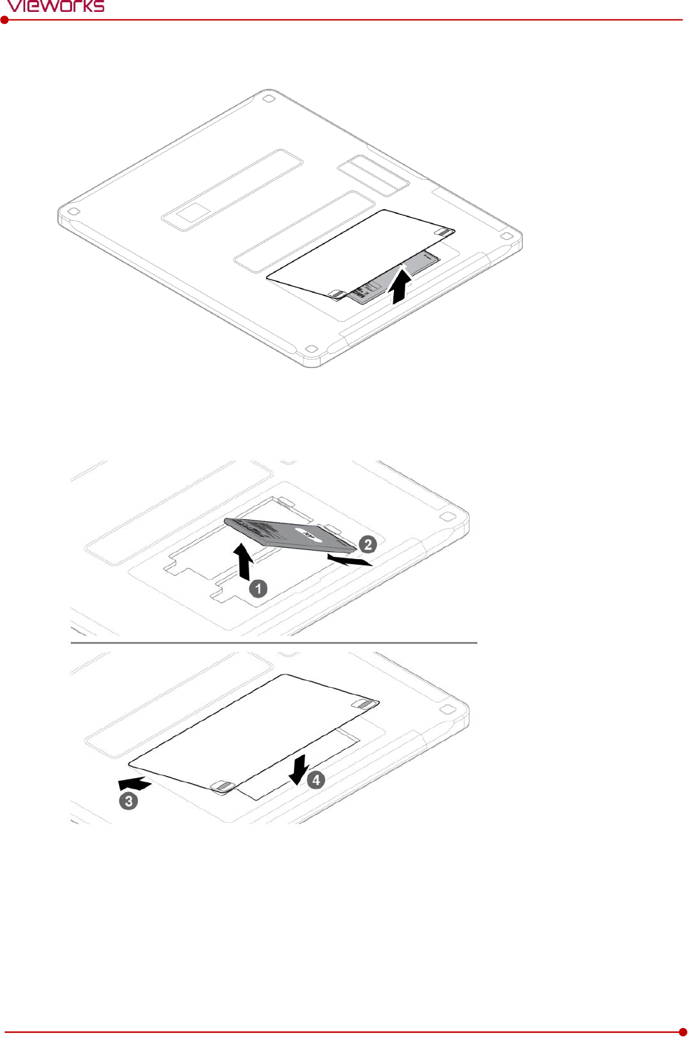
Rev.1.5
Page 63 of 121 D-16-207
VIVIX-S 1417N User Manual
2 Open the battery cover.
3 Take out a battery pack and close the battery cover.
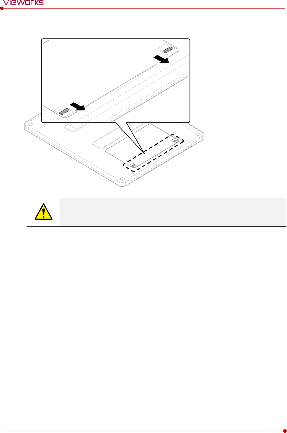
Rev.1.5
Page 64 of 121 D-16-207
VIVIX-S 1417N User Manual
4 Pull down the two lock/unlock levers of a battery case.
Make sure to turn off the detector by pressing and hold the power button for 3 seconds
before detaching a battery pack. All status LED lamps are off and then the detector is
turned off.
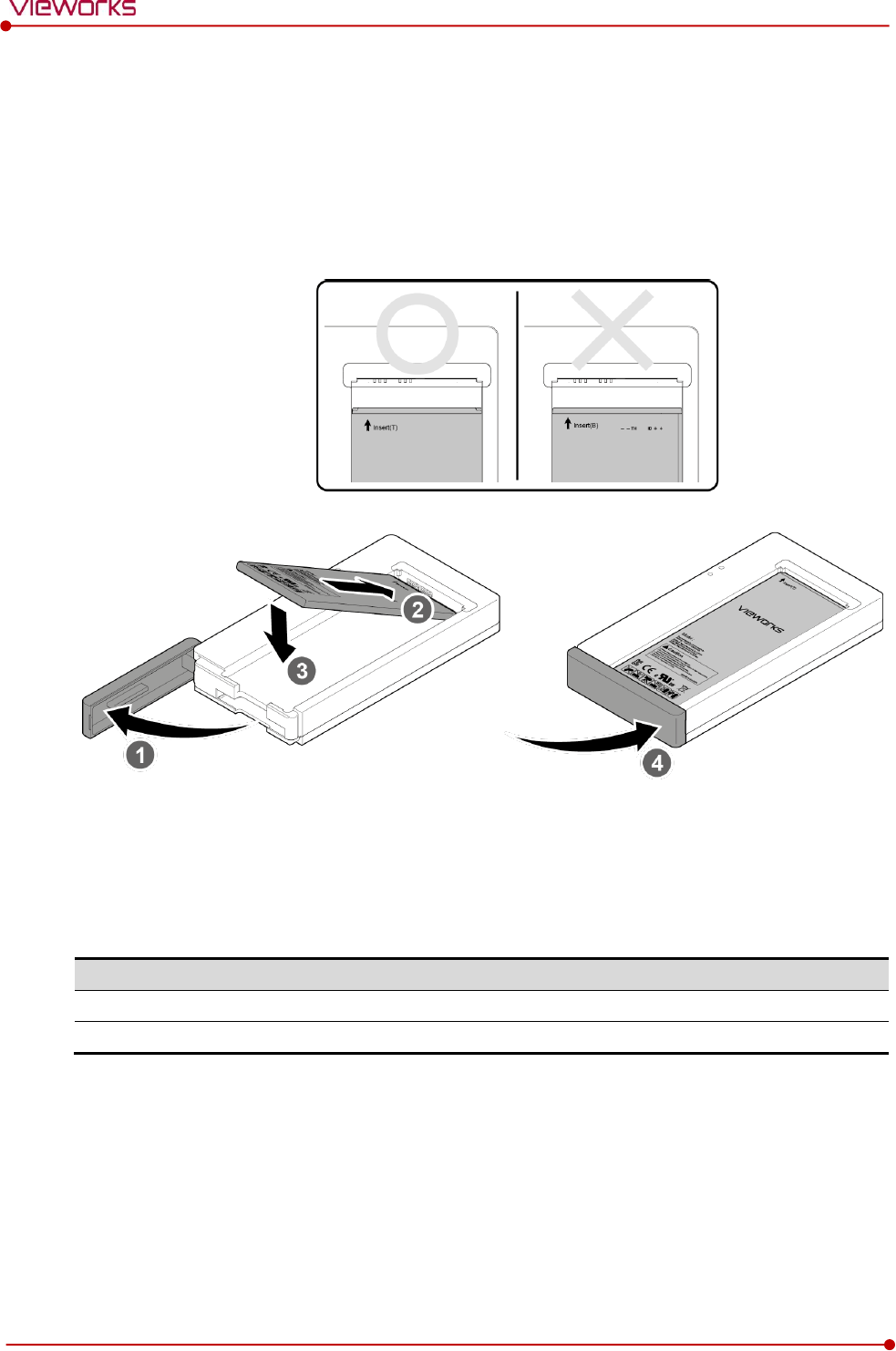
Rev.1.5
Page 65 of 121 D-16-207
VIVIX-S 1417N User Manual
4.1.3 How to charge a battery pack (FXRC-02A)
The detector is battery-operated when it is connected wirelessly. Charge the battery pack fully before
inserting it to the detector.
Charging type 1
Before charging a battery pack, supply power to the charger with a power adapter.
1 Open the cover at the lower side of charger.
2 Put the FXRB-03A battery pack on the top of charger in the right direction.
3 Push the battery down until it is fixed in the charging part.
4 Close the cover at the lower side of charger.
Stimultaneous charging
Charging time
Battery charger
2 battery packs
2 1/2 hrs.
Tether interface cable
2 battery packs
8hrs.
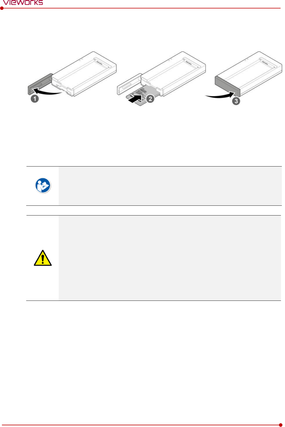
Rev.1.5
Page 66 of 121 D-16-207
VIVIX-S 1417N User Manual
Charging type 2
Before charging a battery pack, supply power to the charger with a power adapter.
1 Open the cover at the lower side of charger.
2 Insert the FXRB-03A battery pack into the slot until it clicks.
Insert the battery pack in the direction of a ‘TOP’ printed part.
3 Close the cover at the lower side of charger.
The charging time can be different depending on temperature and charging status of a
battery.
While charging a battery pack, it is available to use the detector by connecting it with a
tether interface cable.
This detector is designed to make a battery being discharged little by little during the
detector is off. Therefore, remove the battery pack when the detector is not used for
some time. Otherwise, over discharge may occur resulting in the shortened battery life.
Do not use the charger around the paitent.
Charge the battery with the charger provided by Vieworks.
Securely plug the power cord of the charger into the AC outlet. If contact failure occurs,
or if dust/metal objects come into contact with the exposed metal prongs of the plug, fire
or electric shock may result.
Use only a power adapter complying with IEC 60601-1 or IEC 60950-1.
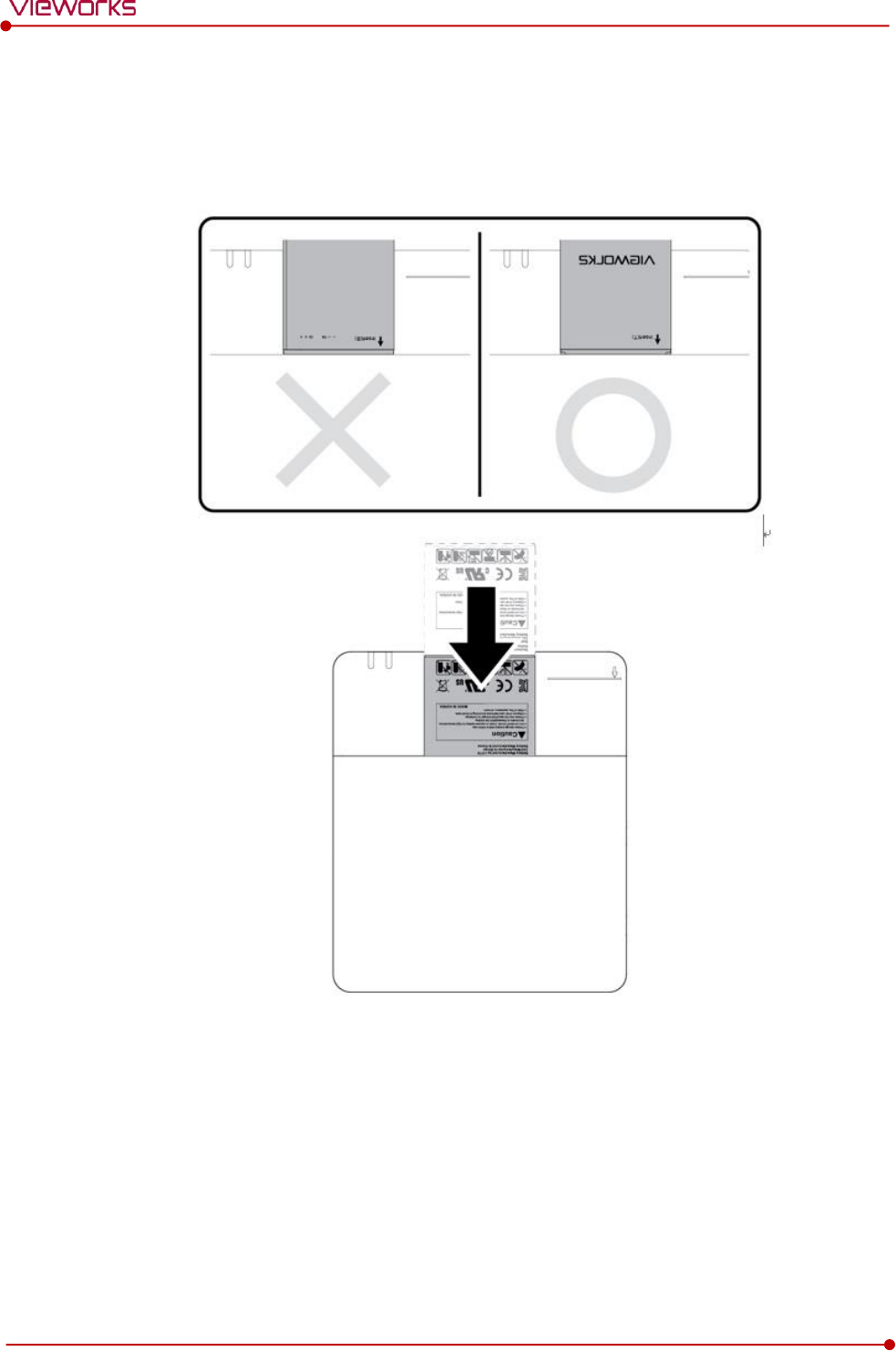
Rev.1.5
Page 67 of 121 D-16-207
VIVIX-S 1417N User Manual
4.1.4 How to charge a battery pack (FXRC-03A)
Charging type 1
Before charging a battery pack, supply power to the charger with a power adapter.
1 Put the FXRB-03A battery pack to the bottom of a charger until it clicks.
2 The battery is started charging automatically. The charger light turns orange / green color when the
battery is being charged / fully charged.
3 Disconnect the battery pack from the charger when the charging is completed.
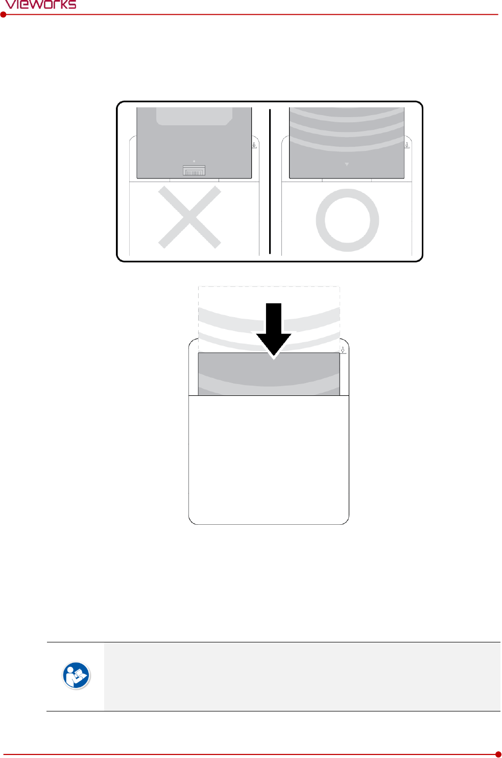
Rev.1.5
Page 68 of 121 D-16-207
VIVIX-S 1417N User Manual
Charging type 2
Before charging a battery pack, supply power to the charger with a power adapter.
1 Put the FXRB-01A battery pack into the slot.
2 The battery is started charging automatically. The charger light turns orange / green color when the
battery is being charged / fully charged.
3 Disconnect the battery pack from the charger when the charging is completed.
The charging time can be different depending on temperature and charging status of a
battery.
While charging a battery pack, it is available to use the detector by connecting it with a
tether interface cable.

Rev.1.5
Page 69 of 121 D-16-207
VIVIX-S 1417N User Manual
This detector is designed to make a battery being discharged little by little during the
detector is off. Therefore, remove the battery pack when the detector is not used for
some time. Otherwise, over discharge may occur resulting in the shortened battery life.
Do not use the charger around the paitent.
Charge the battery with the charger provided by Vieworks.
Securely plug the power cord of the charger into the AC outlet. If contact failure occurs,
or if dust/metal objects come into contact with the exposed metal prongs of the plug, fire
or electric shock may result.
Use only a power adapter complying with IEC 60601-1 or IEC 60950-1.
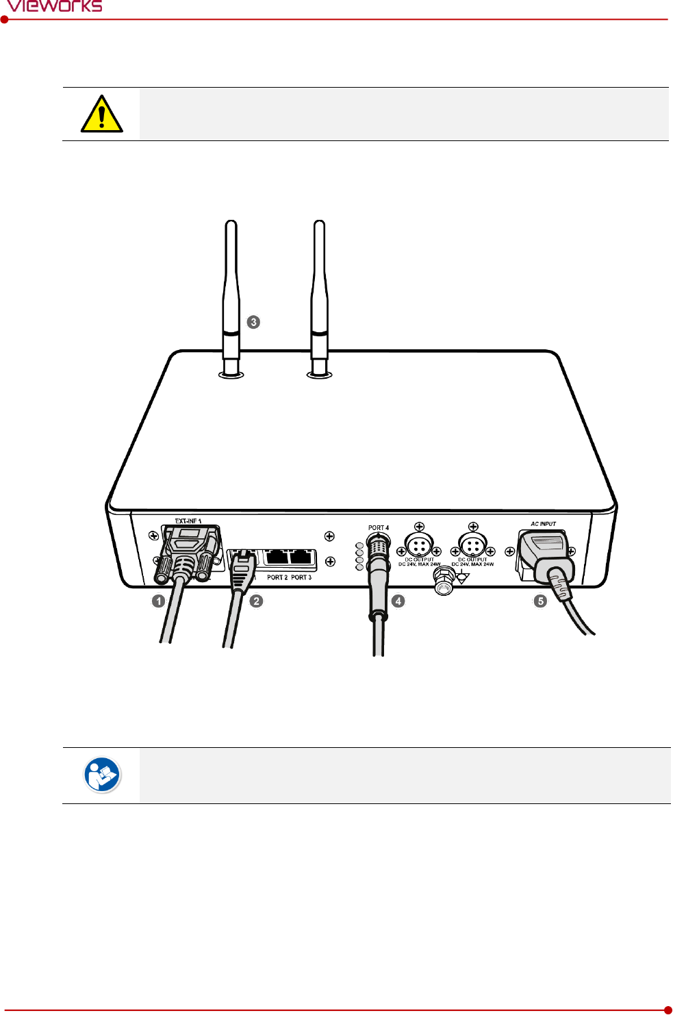
Rev.1.5
Page 70 of 121 D-16-207
VIVIX-S 1417N User Manual
4.2 Product Installation
This equipment should be installed by a service personnel authorized by Vieworks.
This equipment must only be connected to the power with protective earth.
4.2.1 Connecting SCU Basic (FXRS-03A)
1 If you use the DR Trigger interface, connect the one end of generator interface cable to the EXT_INF
port of SCU, and the other to the X-ray generator.
If you use the AED interface, a generator interface cable is not needed as the detector
operates by detecting X-ray automatically.
2 Connect one end of the LAN cable to one of the LAN ports of SCU, and the other to the LAN Card
Connector of workstation assigned for data transfer.
3 Stand the antenna of SCU upright.
4 To transmit image data using a tether interface, connect the one end of the Tether Interface cable to the
Port 4 or Port 5 of SCU and the other to the detector.
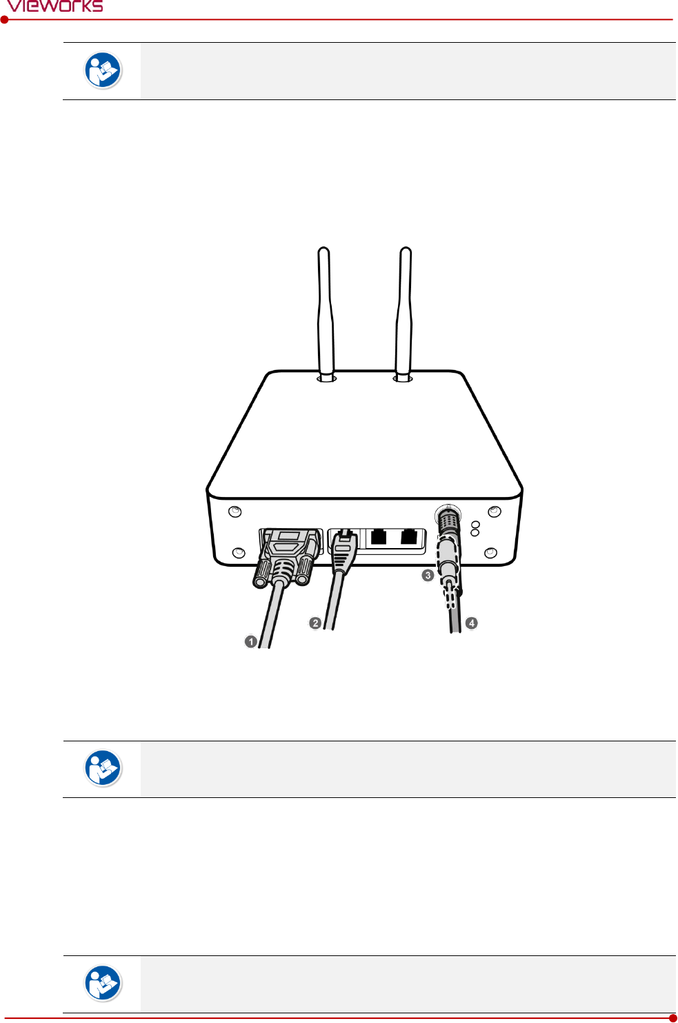
Rev.1.5
Page 71 of 121 D-16-207
VIVIX-S 1417N User Manual
If you use the wireless communication method, a tether interface cable is not needed as
the image is transmitted wirelessly.
5 To supply power, connect the AC power cable to the AC power input port of SCU.
4.2.2 Connecting SCU mini (FXRS-04A)
1 If you use the DR Trigger interface, connect the one end of generator interface cable to the EXT_INF
port of SCU mini, and the other to the X-ray generator.
If you use the AED interface, a generator interface cable is not needed as the detector
operates by detecting X-ray automatically.
2 Connect one end of the LAN cable to one of the LAN ports of SCU mini, and the other to the LAN Card
Connector of workstation assigned for data transfer. Stand the antenna of SCU mini upright.
3 To transmit image data using a tether interface, connect the one end of the tether interface cable to the
port of SCU mini and the other to the detector.
If you use the wireless communication method, a tether interface cable is not needed as
the image is transmitted wirelessly.
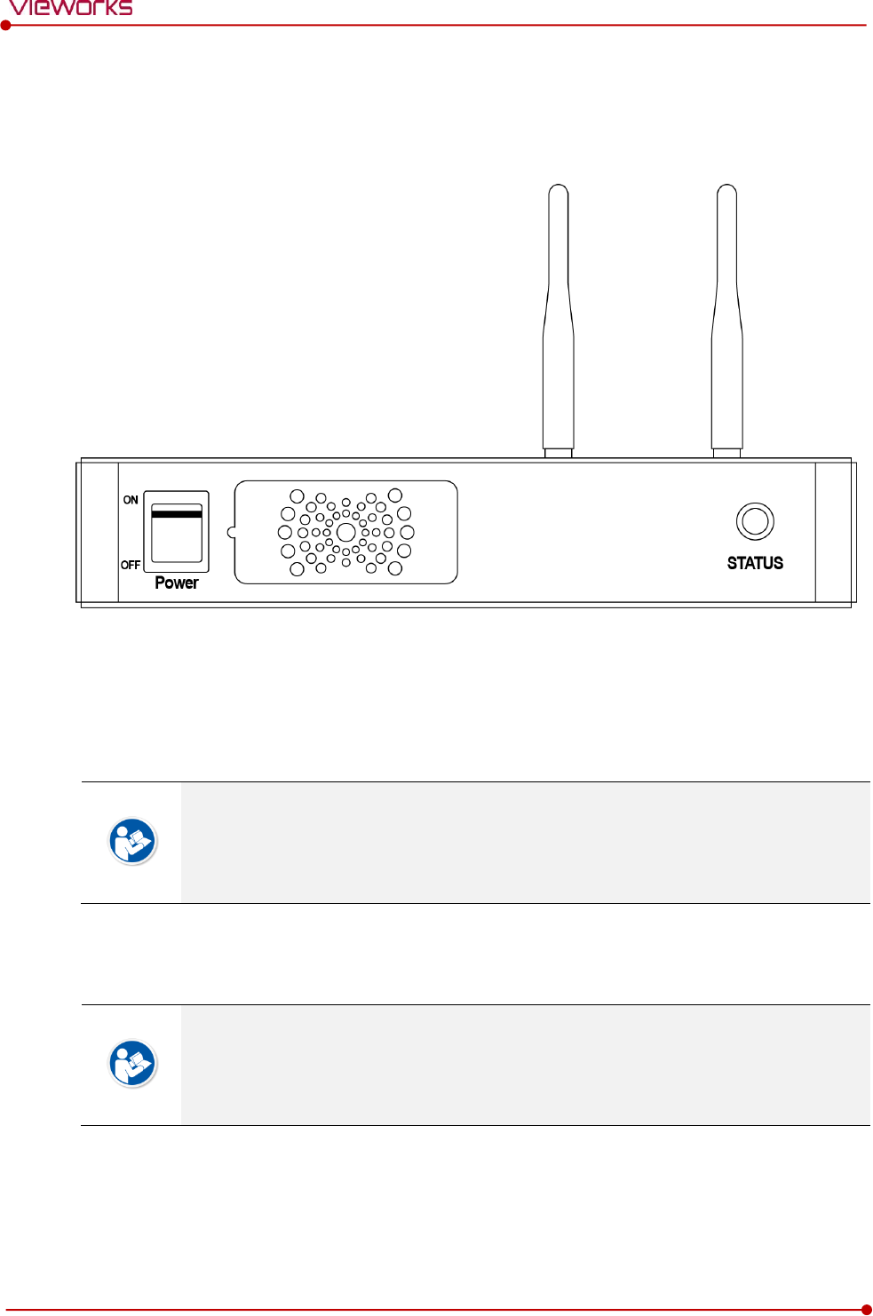
Rev.1.5
Page 72 of 121 D-16-207
VIVIX-S 1417N User Manual
4 To supply power, connect the DC power cable to the DC power input port of SCU mini.
4.2.3 Booting up SCU (Ex. FXRS-03A)
1 Turn on the power switch at the front side of SCU.
2 Check if the power switch of SCU lights up green.
3 Check if the status indicator is blinking in green after the power switch of SCU is permitted.
4 Check if the status indicator of SCU is blinking in green and turns to light up in the same color.
When the power switch lights up green, it means that the power is applied normally.
When the status indicator is blinking in green, the SCU is booting.
If the status indicator lights up green, it indicates that the SCU is being operated normally
after booting up.
4.2.4 Booting up the Detector
The procedures in this chapter are explained according to the default setting status of a
detector (factory reset) and the use of wireless connection.
Refer to <5.3.3 Wireless Initialization of Detector> for the detailed information about the
default setting status of a detector.
1 Attach a charged battery pack to the detector.
2 Press the power button of the detector for 1 second until the power LED is turned on.
3 When the power LED is on, check if it is lit green.
4 Check if the active LED is lit orange on the detector.