Vieworks FXRD1417N X-ray Detector User Manual ViVIX S 1417W x
Vieworks Co., Ltd. X-ray Detector ViVIX S 1417W x
UserManual.wiki
>
Vieworks
>
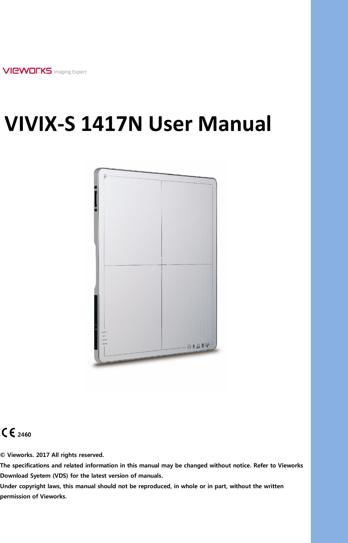
FXRD1417N User Manual
>
User Manual Part 1
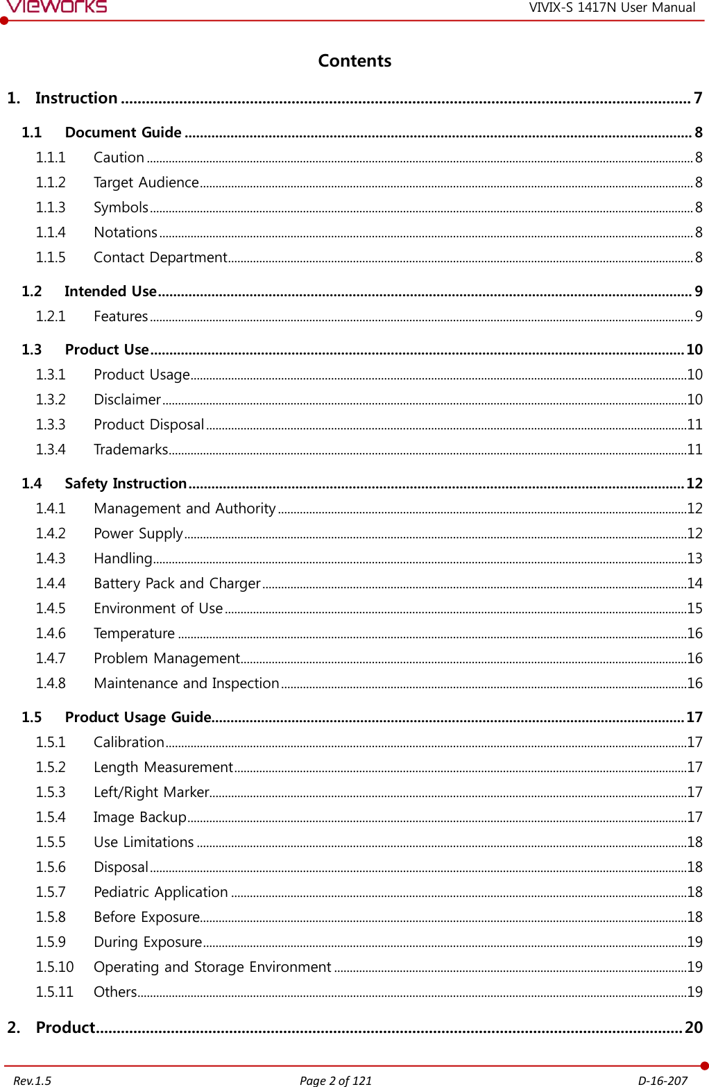
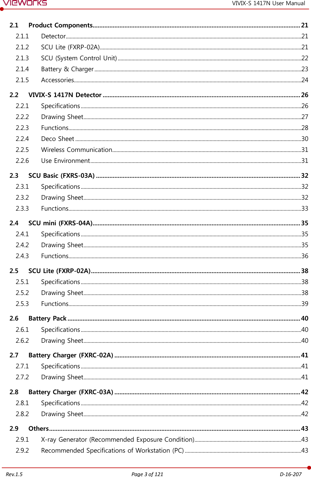
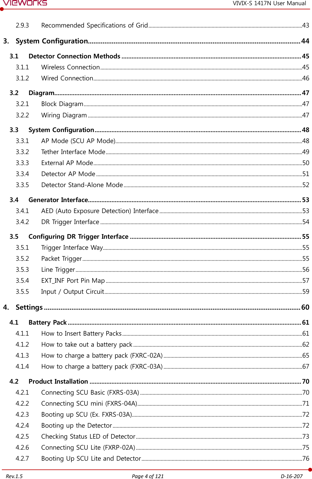
Contents
1.
User Manual Part 1
2.
User Manual Part 2
User Manual Part 1
Navigation menu
Upload a User Manual
Namespaces
Wiki Guide
HTML
PDF
Info
Views
User Manual
Discussion / Help
Navigation