Vieworks FXRD1417N X-ray Detector User Manual ViVIX S 1417W x
Vieworks Co., Ltd. X-ray Detector ViVIX S 1417W x
UserManual.wiki
>
Vieworks
>
FXRD1417N User Manual
>
User Manual Part 2
Contents
1.
User Manual Part 1
2.
User Manual Part 2
User Manual Part 2
Navigation menu
Upload a User Manual
Namespaces
Wiki Guide
HTML
PDF
Info
Views
User Manual
Discussion / Help
Navigation
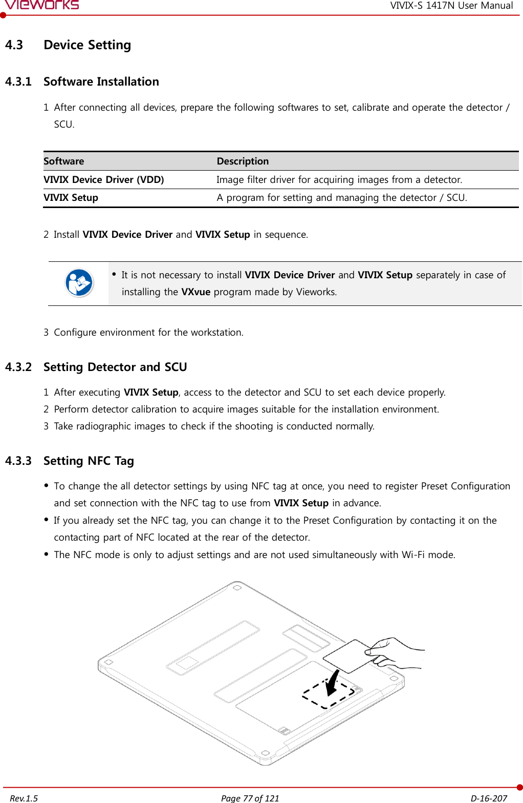
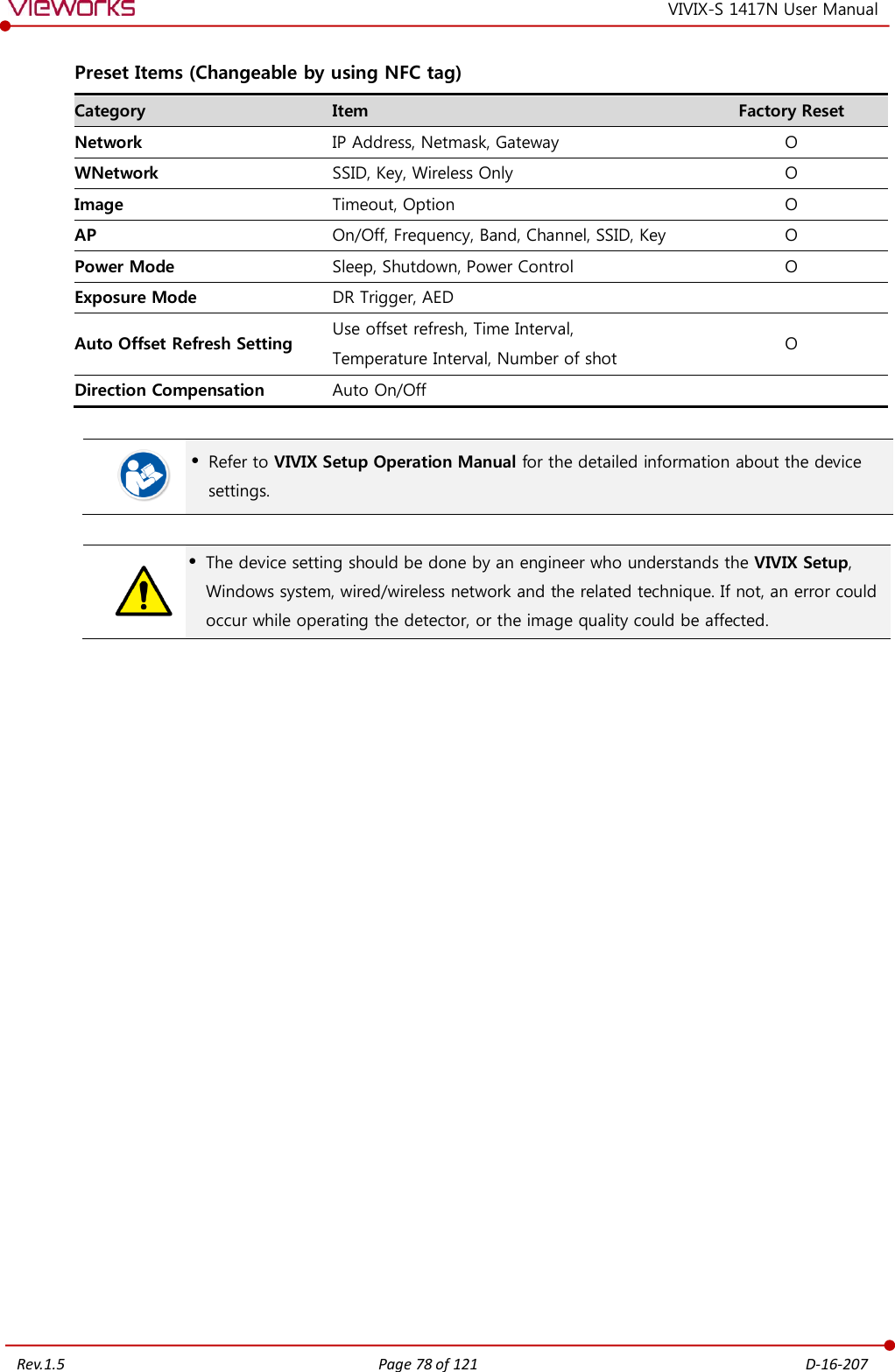
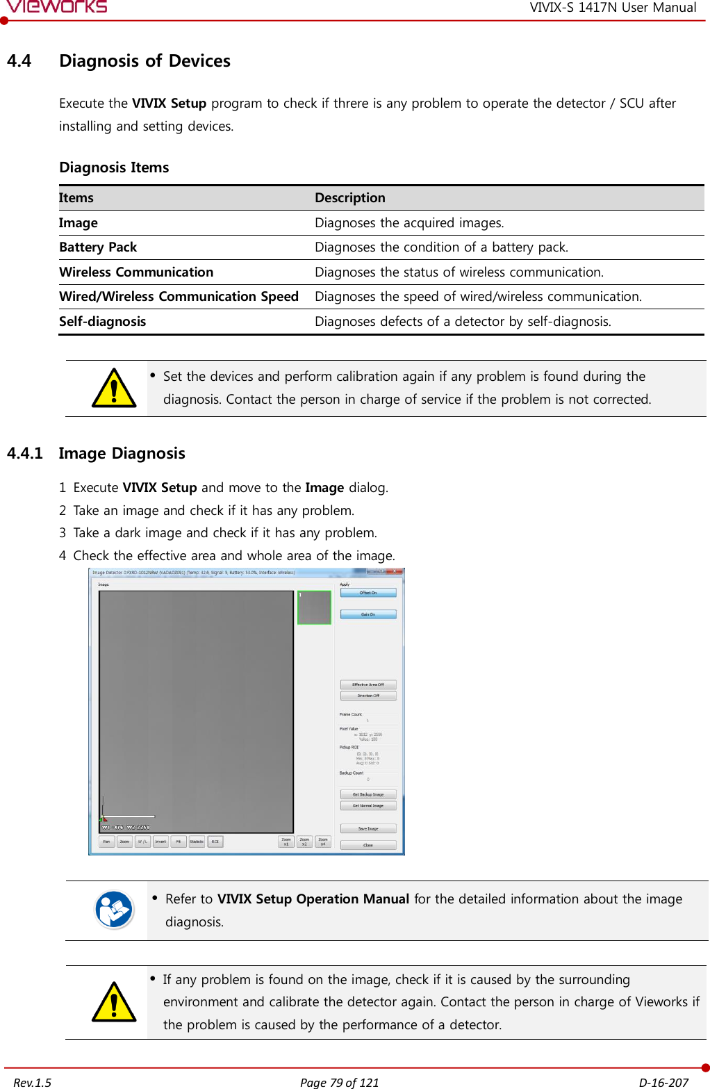
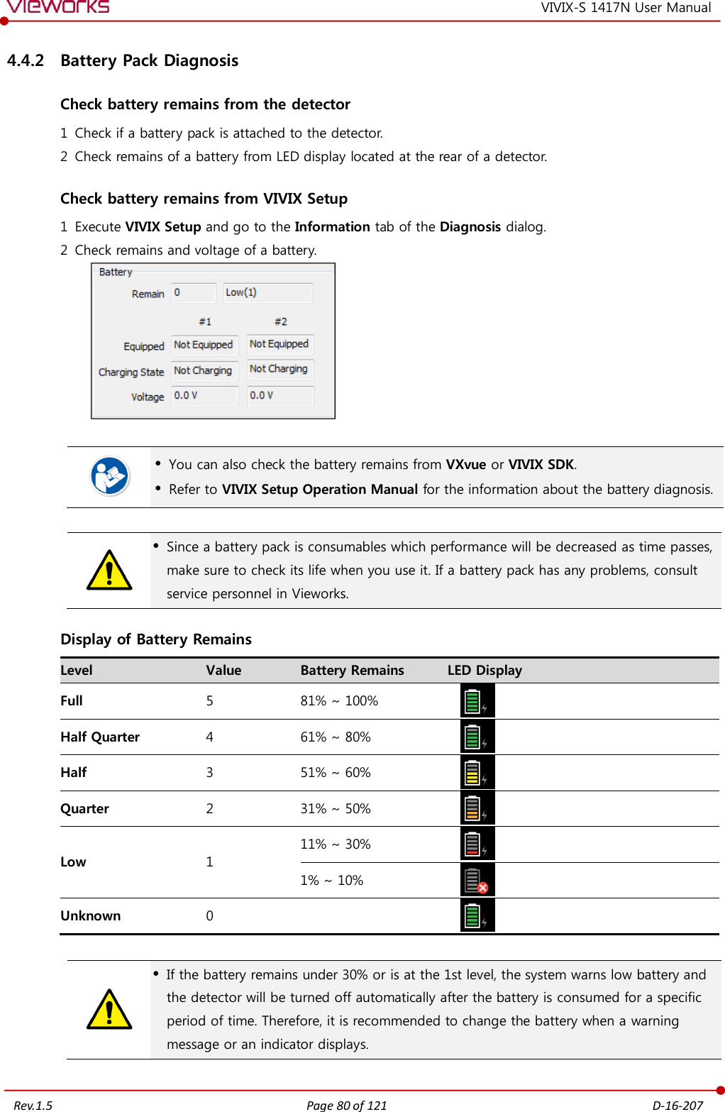
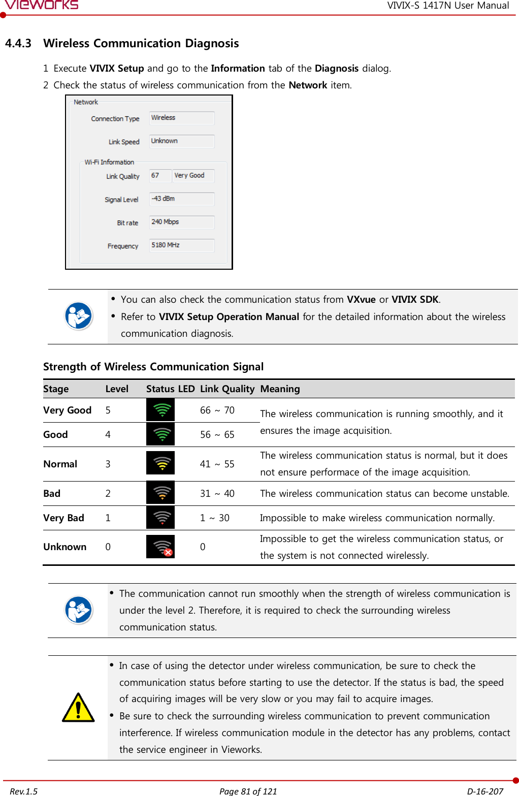
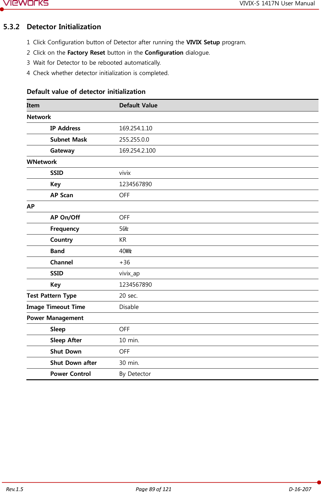
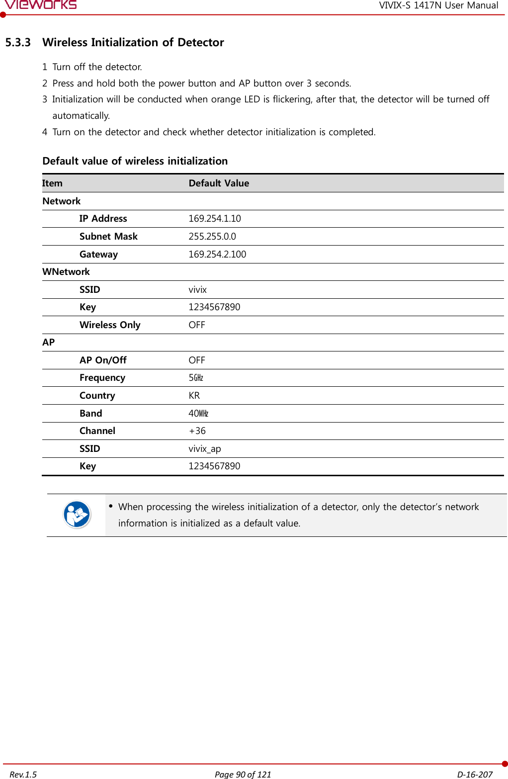
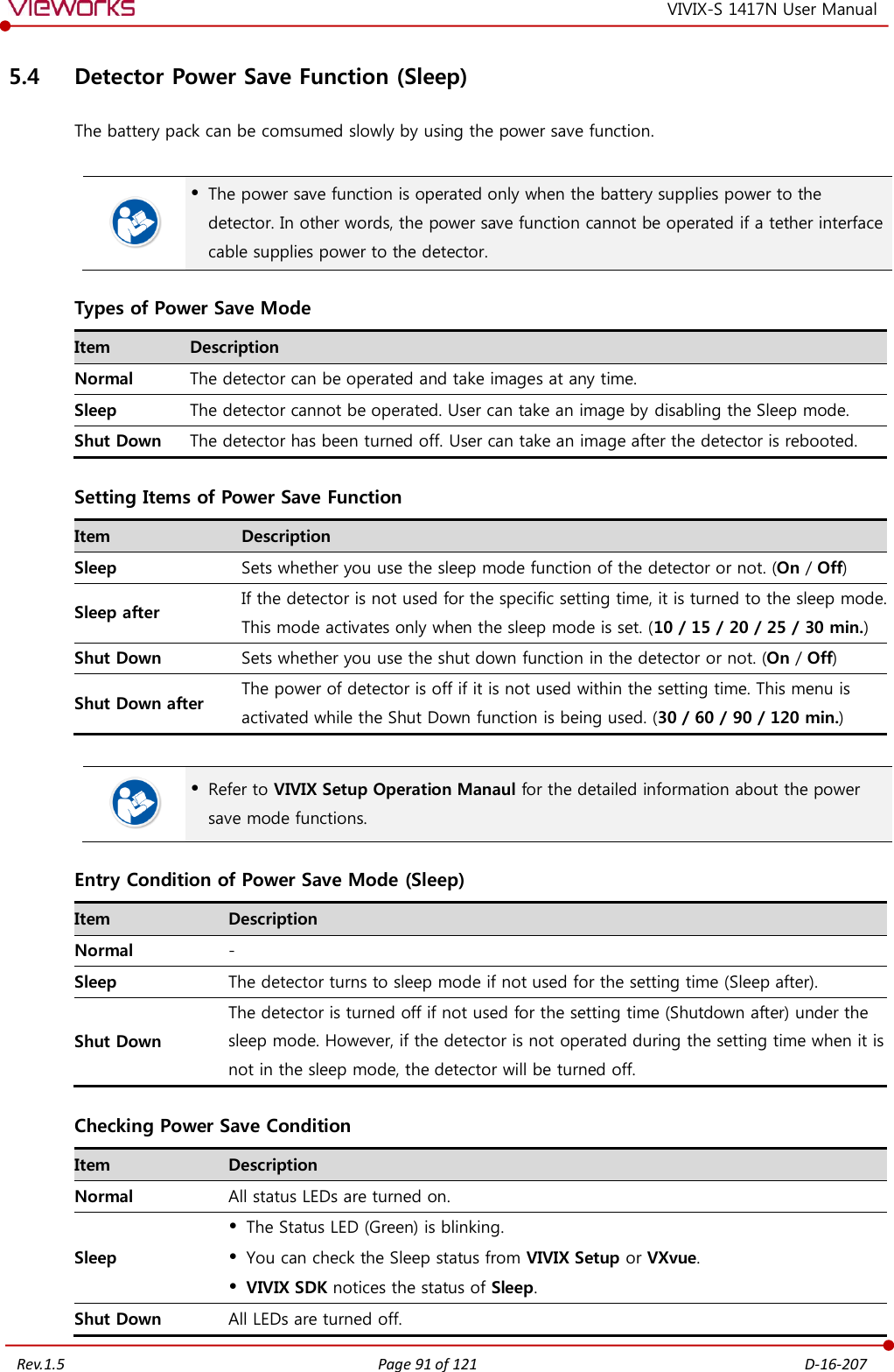
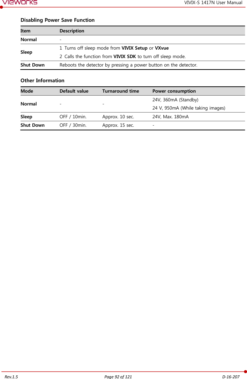
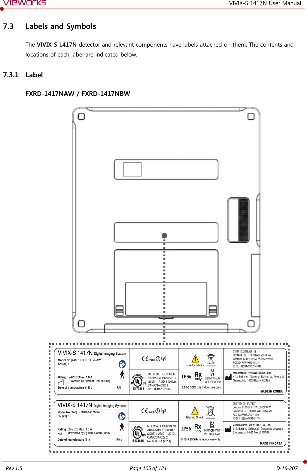
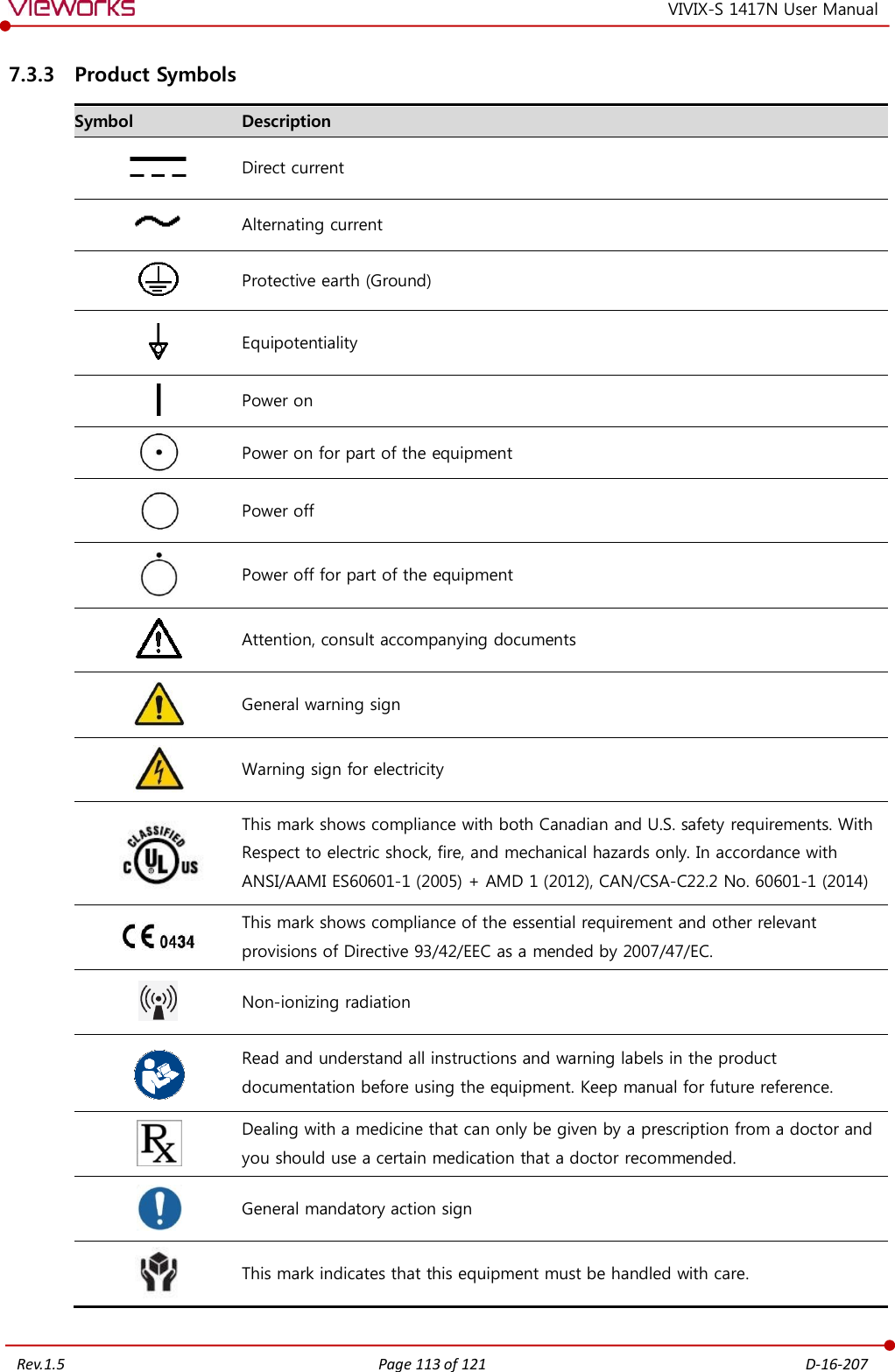
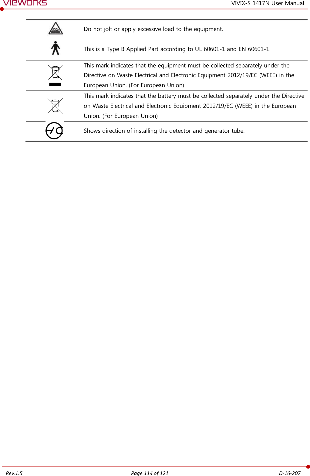
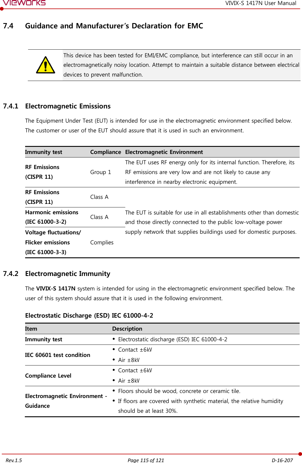
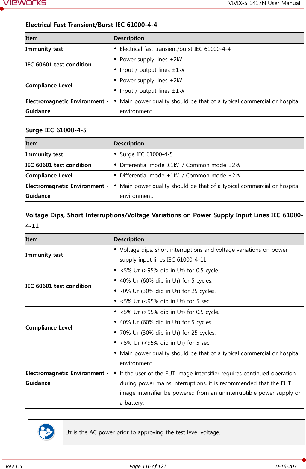
![Rev.1.5 Page 117 of 121 D-16-207 VIVIX-S 1417N User Manual Power Frequency (50/60 ㎐) Magnetic Field IEC 61000-4-8 Item Description Immunity test Power frequency (50/60 ㎐) magnetic field IEC 61000-4-8 IEC 60601 test condition 3 A/m Compliance Level 3 A/m Electromagnetic Environment - Guidance Power frequency magnetic fields should be at levels characteristic of a typical location in a typical commercial or hospital environment. Conducted RF IEC 61000-4-6 / Radiated RF IEC 61000-4-3 Item Description Immunity test Conducted RF IEC 61000-4-6 Radiated RF IEC 61000-4-3 IEC 60601 test condition 3 Vrms 150 ㎑ to 80 ㎒ 3 V/m 80 ㎒ to 2.5 ㎓ Compliance Level 3 Vrms 150 ㎑ to 80 ㎒ 3 V/m 80 ㎒ to 2.5 ㎓ Electromagnetic Environment - Guidance Portable and mobile RF communications equipment should be used no closer to any part of the EUT, including cables, than the recommended separation distance calculated from the below equations applicable to the frequency of the transmitter. P is the maximum output power rating of the transmitter in watts (W) according to the transmitter manufacturer and d is the recommended separation distance in meters (m). Field strengths from fixed RF transmitters, as determined by an electromagnetic site surveya, should be less than the compliance level in each frequency range b. Interference may occur in the vicinity of equipment marked with . At 80 ㎒ and 800 ㎒, the higher frequency range applies. These guidelines may not apply in all situations. Electromagnetic propagation is affected by absorption and reflection from structures, objects and people. Field strengths from fixed transmitters, such as base stations for radio (cellular/cordless) telephones and land mobile radios, amateur radio, AM and FM radio broadcast and TV broadcast cannot be predicted theoretically with accuracy. To assess the electromagnetic environment due to fixed RF transmitters, an electromagnetic site survey should be considered. If the measured field strength in the location in which EUT is used exceeds the applicable RF compliance level above, EUT should be observed to verify normal operation. If abnormal performance is observed, additional measures may be necessary, such as reorienting or relocating EUT. Over the frequency range 150 ㎑ to 80 ㎒, field strengths should be less than [V1] V/m.](https://usermanual.wiki/Vieworks/FXRD1417N.User-Manual-Part-2/User-Guide-3561795-Page-45.png)