Vigil Health Solutions WNCA01 Low Power Transmitter User Manual
Vigil Health Solutions Inc Low Power Transmitter Users Manual
Users Manual
Vigil Wireless Call Station Installation Instructions
Vigil Health Solutions Inc. Page 1
2102 - 4464 Markham Street * Victoria, BC * Canada * V8Z 7X8
Phone: 250.383.6900 Toll Free: 1.877.850.1122
Fax: 250.383.6999 Web: www.vigil.com
REV: JUL2006
V
Vi
ig
gi
il
l®
®
W
Wi
ir
re
el
le
es
ss
s
C
Ca
al
ll
l
S
St
ta
at
ti
io
on
n
W
WN
NC
C
Description
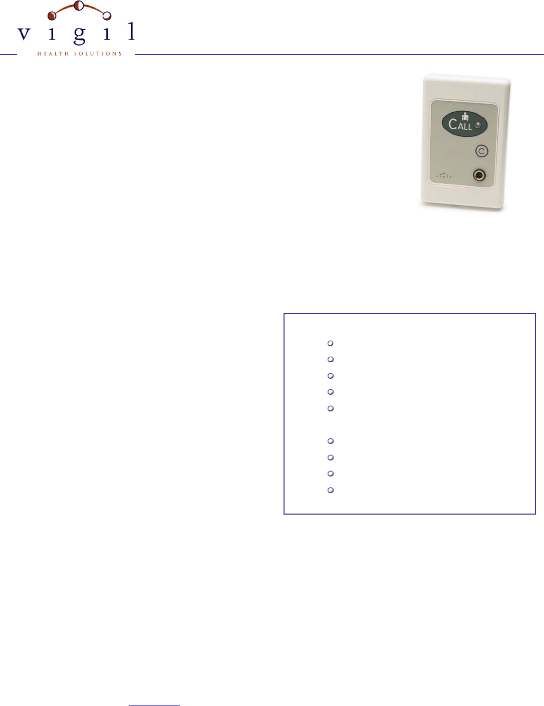
The Vigil® Wireless Nurse Call Station is designed for use with the Vigil® Wireless System.
Wireless Nurse Call Stations are splash resistant and suitable for mounting in resident rooms, dining
rooms, common areas and corridors. The Call Station has a touch sensitive green CALL button with
call-placed LED. An optional call cord socket can be used to connect push button or geriatric call
cords. Call stations also have a touch-sensitive Cancel button to cancel calls at the point of origin.
Operation
To place a call, the user simply presses the green CALL button or activates the call cord. When the Call Station receives confirmation
from the system that the signal has been received, the LED will flash Green. The confirmation process usually takes less than one
second. If for any reason the call station is out of range, or the signal is not confirmed, the LED will flash Red to notify the user to try
again. If the call is successful, the Green LED will continue to flash intermittently until the call is cancelled at the station. To cancel the
call, the responding staff member presses the cancel ‘C’ button.
For stations equipped with call cord sockets, a “Call Cord Out” call
will be raised if the call cord is removed from the socket. This
ensures that staff are alerted if a resident accidentally pulls the call
cord from the station. “Call Cord Out” calls can be cancelled either
by replacing the call cord or by pressing the cancel button. No
dummy plugs are required if the call cord is removed and the call is
cancelled.
When a Call Station is activated, the signal is sent to the nearest
receiver, which then sends a message to the Vigil Central
Computer. The call is displayed on the Vigil® Active Calls Screen
and is also sent to designated pagers or wireless phones. Using the
Vigil® Calls software, the active calls can be displayed on any
computer in the building that is on the facility’s network. The call information displayed on the Active Calls Screen includes the type of
call, the location of the call station, the time the call was activated and the number of subsequent repeat calls that were sent if the call is
not cancelled right away.
When the battery level drops to the minimum operating level, a Low Battery alert will be generated. The Low Battery alert will be
displayed on the Vigil Calls screen and can also be sent to pagers or phones. See the Specifications section for battery details and
instructions for replacing batteries.
Features
Intelligent Transceiver Technology
Cancel at Origin of Call
Visual Confirmation of Signal Reception
Visual Indication when Station Active
Visual Confirmation when Call Cancelled
Optional Call Cord Socket
Variety of Call Cords Available
Long Life Battery
Low Battery Alert
Vigil Wireless Call Station Installation Instructions
Vigil Health Solutions Inc. Page 2
2102 - 4464 Markham Street * Victoria, BC * Canada * V8Z 7X8
Phone: 250.383.6900 Toll Free: 1.877.850.1122
Fax: 250.383.6999 Web: www.vigil.com
REV: JUL2006
Installation Instructions
Wireless call stations are typically mounted in a single gang surface mount wall box. Follow the instructions below when installing a
station:
1. Mount wall box on wall using suitable screws for the type of construction.
2. Insert battery into station observing correct polarity. Observe the LED’s on the device. When the battery is first installed you
will see the Green LED blink on and off for about 30 seconds followed by one longer blink and then a very short blink. This
sequence indicates that the device has successfully found the network. If the station blinks RED refer to the Troubleshooting
guide.
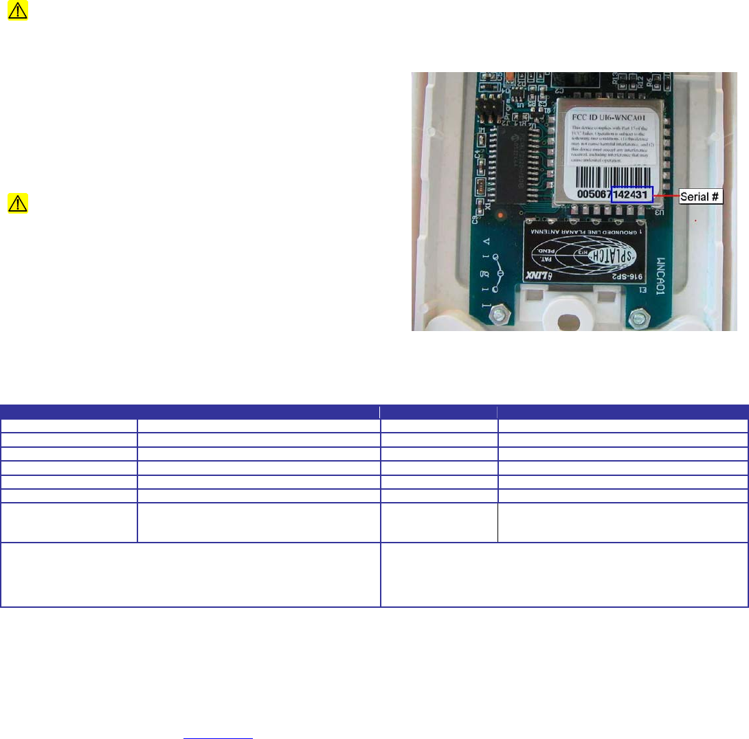
3. Record Serial # (Transmitter ID#) from back of device. Location of the serial number is shown below.
4. Screw mount the station to the wall box.
Do not mount Wireless Stations on or near metal objects (HVAC, I Beams, etc) or electrical devices (motors, high
voltage switching, etc) as they can interfere with the wireless signals
Location of serial number
The last six digits of the serial number (“142431” in the example) are
needed when configuring the Vigil Central Computer.
The Splatch antenna model 916-SP2 is permanently attached to the
circuit board.
Caution: Any changes or modifications not expressly
approved by the party responsible for compliance could void the
user's authority to operate the equipment.
Specifications
PHYSICAL ELECTRICAL
Height 127mm (5.0”) Operating Voltage 3.3V
Width 83mm (3.26”) Wireless 900MHz FHSS Transceiver
Depth 38mm (1.5”) Standing Current 20mA
Weight 153 grams Operating Current 40mA TX/RX
Enclosure High impact white plastic enclosure Battery Type 1/2AA 3.6V Lithium
Accessories Optional Call Cords Battery Life 5-8 yrs average use
Temperature Ratings
Operating:
Storage/Transport
-0°C to 50°C (32°F to 122°F)
-55°C to 85°C (-67°F to 185°F) FCC ID UI6-WNCA01
To replace battery, remove the surrounding faceplate and unscrew the
station from the wall box. Replace with same battery type, observing
polarity. Take care when handling the circuit board. Replace screws and
faceplate.
Compliance: This Device complies with Part 15 of the FCC Rules.
Operation is subject to the following two conditions: (1) This device may
not cause harmful interference, and (2) This device must accept any
interference received, including interference that may cause undesired
operation.