Villa Sistemi Medicali S p A 76593030 Modular Wireless remote control for radiological unit User Manual Title
Villa Sistemi Medicali S.p.A. Modular Wireless remote control for radiological unit Title
User Manual
Release May 6, 2014 (Draft)
AB
0051
CDEFD
CDEFDCDEFD
CDEFD

SERVICE MANUAL
Revision history
(Rev. 1) ENDOGRAPH DC
DFE
DFEDFE
DFED
DD
D
Rev. Date Page/s Modification description
0 14.02.13 - Document approval.
1 04.09.13 12, 13, 28,
31, 36,
42, 86, 88, 90
FDA approved revision.
Added note on spacer insertion during stand arm set
assembling.
Mains plug on mobile stand version no more
supplied.
Spare Parts update.
(Ref. RDM 7723, RDM 7763, RDM 7773, RDM 7797, RDM 7836)

SERVICE MANUAL
Revision history
ENDOGRAPH DC (Rev. 1)
THIS PAGE IS INTENTIONALLY LEFT BLANK

SERVICE MANUAL
Contents
(Rev. 1) ENDOGRAPH DC
i
Contents
1. INTRODUCTION 1
1.1
Icons in the manual................................................................................ 1
1.2
How to contact VILLA SISTEMI MEDICALI technical service................... 2
2. SAFETY ASPECTS 3
2.1
Warnings ................................................................................................ 4
2.1.1
Electromagnetic emissions...................................................................5
2.1.2
Electromagnetic immunity...................................................................6
2.1.3
Recommended separation distances to portable and
mobile radio equipment .......................................................................8
2.2
Protection from X-rays............................................................................ 9
2.3
Environmental risks and disposal ........................................................ 10
2.4
Symbols in use ..................................................................................... 11
3. DESCRIPTION 12
3.1
Identification plates .............................................................................. 12
3.2
Functions, Models and Versions........................................................... 14
3.2.1
High Frequency (HF) Generator.......................................................... 15
3.2.2
Extension arm and scissors arm........................................................ 15
3.2.3
Tube-head......................................................................................... 16
3.2.4
Timer ................................................................................................ 16
3.3
Configurations...................................................................................... 17
3.3.1
Standard configuration...................................................................... 17
3.3.2
Remote timer configuration ............................................................... 18
3.3.3
Mobile stand configuration ................................................................ 19
3.3.4
Remote X-ray button configuration .................................................... 20
3.3.5
Configuration with wireless X-ray button ........................................... 21
4. TECHNICAL DATA 22
4.1
Method for measuring technical factors................................................ 25
4.2
Curves tube features ............................................................................ 26
4.3
Reference standard............................................................................... 28
4.4
Dimensions .......................................................................................... 30
5. PRE-INSTALLATION 31
5.1
Mounting methods ............................................................................... 31
5.2
Electric pre-setting ............................................................................... 32
6. INSTALLATION 33
6.1
Wall installation ................................................................................... 33
6.1.1
Timer set up (standard configuration) ................................................ 34
6.2
Assembling the mobile stand and timer installation ............................. 35

SERVICE MANUAL
Contents
ENDOGRAPH DC (Rev. 1)
ii
6.3
Assembling the arms ............................................................................ 37
6.3.1
Assembling the extension arm........................................................... 37
6.3.2
Assembling the scissors arm (DP arm) ............................................... 39
6.3.3
Assembling the stand arms set.......................................................... 44
6.4
Installation of the optional parts........................................................... 45
6.4.1
External signaling devices ................................................................. 45
6.4.2
Remote X-ray button......................................................................... 46
6.4.3
Wireless X-ray button ....................................................................... 48
6.4.3.1
Wireless X-ray button –battery assembling ......................... 48
6.4.3.2
Wireless upgrade kit assembling ........................................ 49
6.4.3.3
Wireless X-ray button – Timer matching ............................. 51
6.4.4
Remote Timer configuration............................................................... 52
6.4.4.1 Wall support set-up ........................................................... 52
6.4.4.2 Remote Timer set up.......................................................... 53
6.4.5
Installation of chemical screws .......................................................... 54
6.5
Electrical connection ............................................................................ 55
6.5.1
Electrical connection for standard and mobile stand versions............. 55
6.5.2
Electrical connection for Remote Timer version .................................. 57
6.5.2.1 Wall support connection .................................................... 57
6.5.2.2 Remote Timer connection................................................... 58
6.6
Power-up sequence............................................................................... 59
7. CHECKS, CALIBRATIONS AND ADJUSTMENTS 60
7.1
Arm adjustment.................................................................................... 60
7.1.1
Adjusting the extension arm support frictioning mechanism .............. 61
7.1.2
Adjusting the extension arm frictioning mechanism ........................... 62
7.1.3
Adjusting the balance scissors arm.................................................... 63
8. SET-UP 65
9. TROUBLESHOOTING 71
9.1
Error messages on the display.............................................................. 72
9.1.1
Fatal errors upon power-up and in the ready, idle and cooling statuses73
9.1.2
Fatal errors during X-ray emission .................................................... 74
9.1.3
NON fatal errors................................................................................ 75
10. REPLACING PARTS 76
10.1
Replacing the tubehead and the Driver board....................................... 76
10.1.1
Replacing the tubehead..................................................................... 77
10.1.2
Replacing the Driver board................................................................ 77
10.2
Replacing the CPU board ...................................................................... 78
10.3
Replacing the keypad............................................................................ 79
10.4
Replacing the scissors arm ................................................................... 80
10.4.1
Replacing the scissors arm with wall timer (standard configuration) ... 80
10.4.2
Replacing the scissor arm on mobile stand ........................................ 81

SERVICE MANUAL
Contents
(Rev. 1) ENDOGRAPH DC
iii
11. MAINTENANCE 82
12. SCHEMATICS AND DRAWINGS 83
13. SPARE PARTS 87
14. FIXING TEMPLATES 99
This publication can only be reproduced, transmitted, transcribed or translated
into any human or computer language with the written consent of the
Manufacturer.
This Manual in English is the original version.

SERVICE MANUAL
Contents
ENDOGRAPH DC (Rev. 1)
iv
THIS PAGE IS INTENTIONALLY LEFT BLANK

SERVICE MANUAL
Introduction
(Rev. 1) ENDOGRAPH DC
1
B
BB
B
NOTE:
This manual is updated for the product it is sold with, in order to
guarantee an adequate reference to use the product properly and safely.
The manual may not reflect changes to the product that do not affect
operating modes or safety.
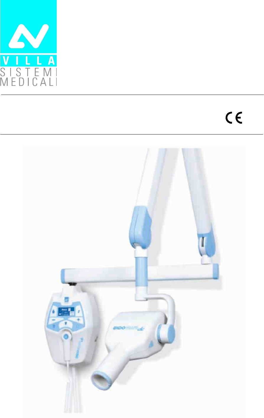
The Endograph DC intra-oral X-ray unit takes high quality intra-oral X-
rays thanks to reduced exposure times and the small dimensions of the
focus spot.
Endograph DC is intended exclusively for intra-oral X-rays.
System operation is managed by a microprocessor, which permits high
reproducibility of the exposure times.
The system consists of the following parts:
• timer: Endograph DC complete with the wall support
• extension arm (30cm, 60 cm or 80cm for the wall version)
• Scissors arm (DP)
• Tube-head (60-65-70) kV ; 6 mA
The aim of this manual is to instruct the user on the safe and effective
use of the device.
The device must be used in compliance with the procedures described,
and never be used for purposes different from those herewith indicated.
D
DD
D
Indicates a “NOTE”; we recommend particular attention in reading the
subjects identified with this icon.
Indicates a “WARNING”; subjects identified with this icon concern
safety aspects regarding the patient and/or the operator.

SERVICE MANUAL
Introduction
ENDOGRAPH DC (Rev. 1)
2
ACCB
ACCBACCB
ACCB
DDEFD
DDEFDDDEFD
DDEFD
For any technical queries please contact the following:
• Telephone number +39 02 48859.1
• Fax number +39 02 48859222
• E-mail: dentalservice@villasm.com

SERVICE MANUAL
Safety aspects
(Rev. 1) ENDOGRAPH DC
3
CCBC
CCBCCCBC
CCBC
WARNING:
Please read this chapter thoroughly.
VILLA SISTEMI MEDICALI designs and builds the devices in compliance
with the safety requirements; furthermore it supplies all information
necessary for correct use, and the warnings related to danger associated
with X-ray generating units.
The manufacturer cannot be held responsible for:
• use of Endograph DC equipment different from the purpose for
which it was originally designed,
• damage to the unit, the operator or the patient, caused both by
incorrect installation and maintenance procedures different from
those described in this user and service manuals supplied with the
unit, and by wrong operations,
• mechanical and/or electrical modifications performed during and
after the installation, different from those described in the service
manual.
Only personnel authorised by the manufacturer may carry out
technical operations on the unit.
Only authorised personnel can remove the tube-head from its
support and/or access the components under tension.
SERVICE MANUAL
Safety aspects
ENDOGRAPH DC (Rev. 1)
4
E
EE
E
The device must be used in compliance with the procedures described
and never be used for purposes different from those herewith indicated.
Before performing any maintenance operation, disconnect the unit from
the power supply using the provided circuit breaker.
Endograph DC is an electro-medical device and therefore it can be used
only under the supervision of suitably qualified medical personnel, with
the necessary knowledge on X-ray protection.
The user is responsible for the fulfilment of the legal requirements
regulating the ownership, installation and use of the equipment itself.
Endograph DC has been built to support continuous operation at
intermittent load; therefore please follow the described use cycles.
Wherever necessary, use the appropriate accessories, such as the leaded
aprons, to protect the patient from radiation.
Endograph DC must be turned off when using electrosurgical devices or
similar equipment near the unit.
This device has not been designed to be used in environments where
anaesthetic mixtures flammable with air, oxygen or nitrous oxide can be
detected.
In order to prevent risks of short-circuit and corrosion, avoid the entry of
water or other liquids in the equipment.
The parts of the unit that can come into contact with the patient must be
cleaned regularly according to the instructions provided below in this
document.
WARNING:
For safety reasons, it is prohibited to abnormally overload the extension
arm or the scissors arm, for example by leaning on it.
SERVICE MANUAL
Safety aspects
(Rev. 1) ENDOGRAPH DC
5
DEDD
DEDDDEDD
DEDD
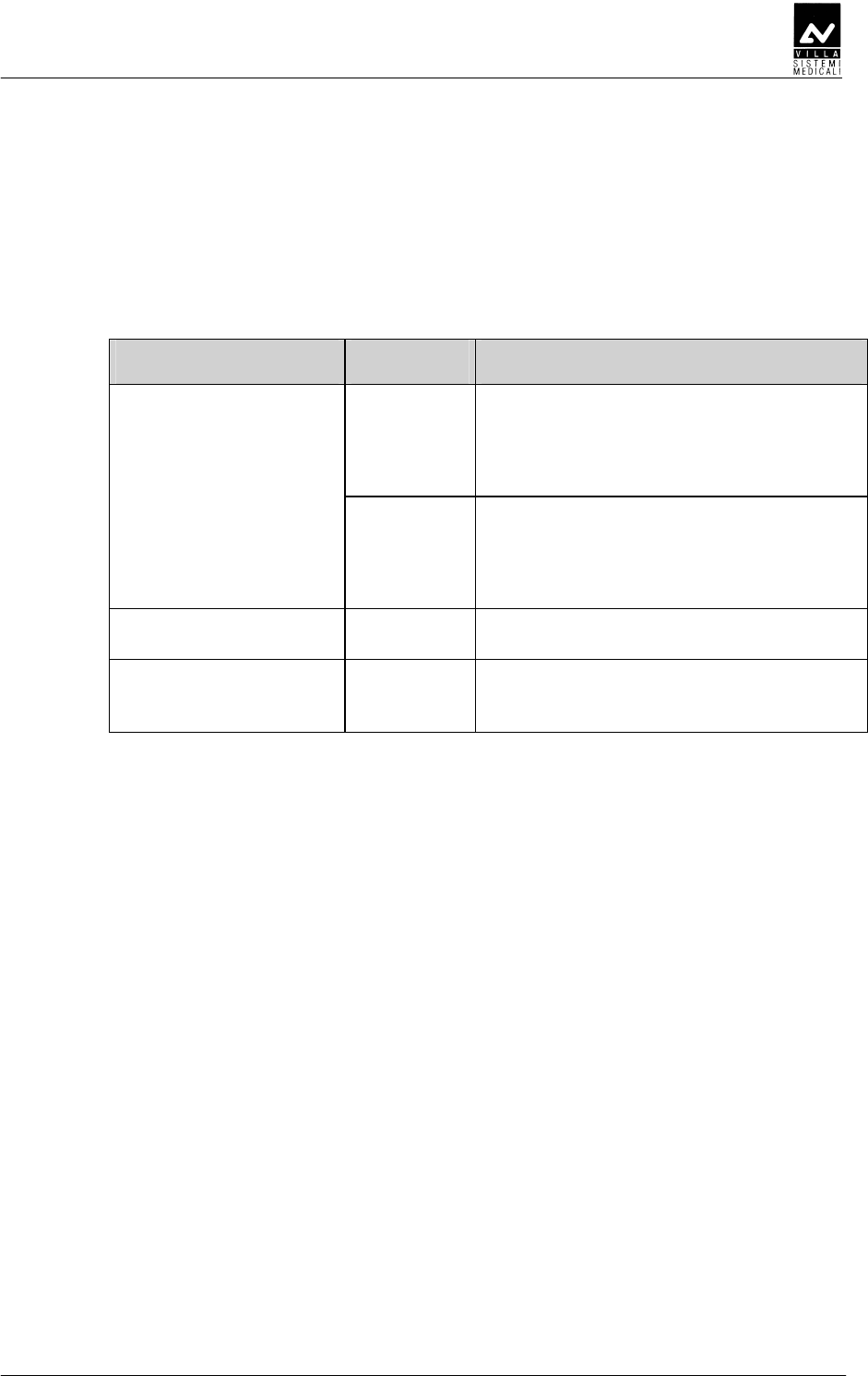
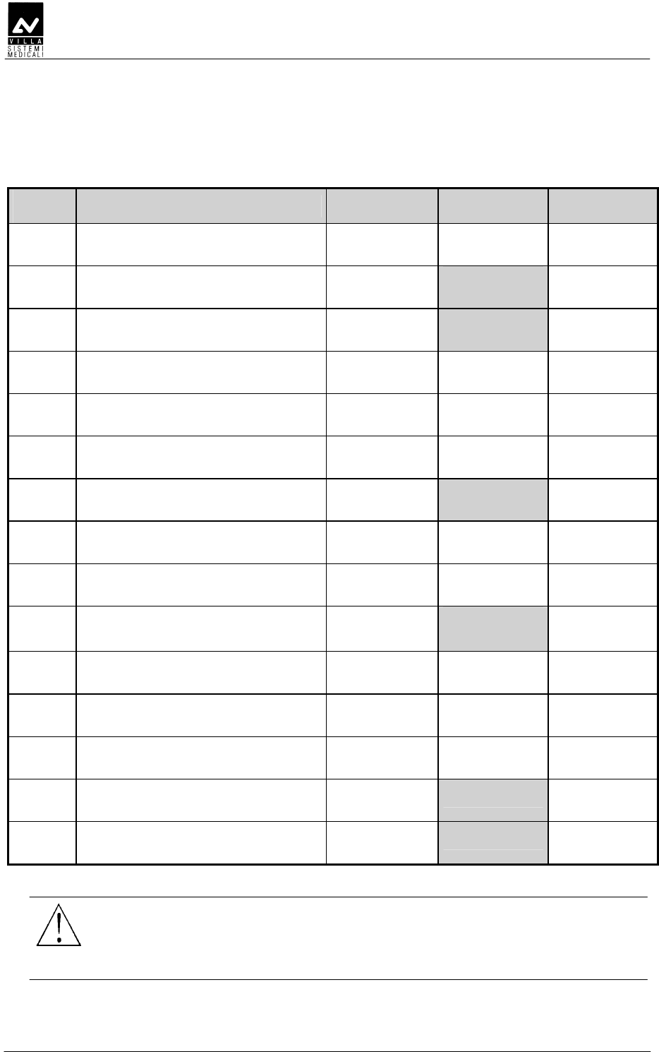
In accordance with the IEC 60601-1-2 standard, Endograph DC is
suitable for use in the electromagnetic environment specified below.
The customer or user of the system must ensure that it is used in the
said environment.
Emissions test Conformity
EMC environment of use
Class B Endograph DC is suitable for use in all
domestic environments and in
environments directly connected to the
mains power supply at low voltage that
supplies buildings for domestic use.
RF emissions
CISPR 11
Group I Endograph DC uses RF power only for its
internal functioning. As a result, its RF
emissions are very low and most likely
will not cause any interference in
electronic devices located nearby.
Harmonic emissions
IEC 61000-3-2
Class A
Flicker/voltage
fluctuation emissions
IEC 61000-3-3
In
compliance

SERVICE MANUAL
Safety aspects
ENDOGRAPH DC (Rev. 1)
6
DED
DEDDED
DED
In accordance with the IEC 60601-1-2 standard, Endograph DC is
suitable for use in the electromagnetic environment described below.
The customer or user of the system must ensure that it is used in the
said environment.
Immunity test Test level
IEC 60601-1-2 Compliance level EMC environment
of use
Electrostatic
discharges (ESD)
IEC 61000-4-2
± 6 kV contact
± 8 kV in air
± 6 kV contact
± 8 kV in air
The flooring must be
must be wood, concrete
or ceramic tile. If the
flooring is covered with
synthetic material, the
relative humidity must
be at least 30%.
Transients/sequence
of rapid electric
impulses
IEC 61000-4-4
± 2 kV for power
supply lines
± 1 kV for
input/output lines
± 2 kV for power
supply lines
± 1 kV for
input/output lines
The quality of the mains
voltage must be the
same as a typical
commercial or hospital
environment.
Overvoltages
IEC 61000-4-5
± 1 kV between
phases
± 2 kV between phase
and earth
± 1 kV between
phases
± 2 kV between phase
and earth
The quality of the mains
voltage must be the
same as a typical
commercial or hospital
environment.
Voltage dips, short
breaks and voltage
variations of the
power supply feed
line IEC 61000-4-11
0 % U
t
for 0.5 cycles
40 % U
t
for 5 cycles
70 % U
t
for 25 cycles
0 % U
t
for 5 s
0 % U
t
for 0.5 cycles
40 % U
t
for 5 cycles
70 % U
t
for 25 cycles
0 % U
t
for 5 s
The quality of the mains
voltage must be the
same as a typical
commercial or hospital
environment. If the
Endograph DC user
requires continuous
operation during
interruptions in the
mains voltage, it is
recommended to power
the Endograph DC with
an uninterrupted power
supply or batteries.
Magnetic field at the
main frequency
(50/60 Hz)
IEC 61000-4-8
3 A/m 3 A/m The levels of the
magnetic fields at mains
frequency must be the
same as a typical
commercial or hospital
environment.
Note: U
t
is the a.c. mains voltage prior to the application of the test level.
SERVICE MANUAL
Safety aspects
(Rev. 1) ENDOGRAPH DC
7
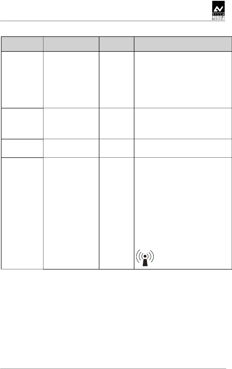
Immunity test
Test level
IEC 60601-1-2
Compliance
level EMC environment of use
The RF portable and mobile
communications units should not be
used closer to any part of the
Endograph DC, including cables, than
the recommended separation distance
calculated from the equation
applicable to the frequency of the
transmitter.
Recommended separation distance:
Radiated RF
IEC 61000-4-3
3 V/m
from 80 MHz to
2.5 GHz
3 V/m d = 1.2 x
√
P from 80 MHz to
800 MHz
d = 2.3 x
√
P from 800 MHz to
2.5 GHz
Conducted RF
IEC 61000-4-6
3 V
from 150 kHz to
80 MHz
3 V d = 1.2 x
√
P
where "P" is the maximum rated
output of the transmitter in watts (W)
according to the transmitter
manufacturer and "d" is the
recommended separation distance in
meters (m).
The field strength of the fixed RF
transmitters, determined by an on-site
electromagnetic survey, should be
lower than the compliance level in
each frequency range.
Interference may be verified near
devices marked with the following
symbol:
SERVICE MANUAL
Safety aspects
ENDOGRAPH DC (Rev. 1)
8
D
DD
DDDDEDED
DDDEDEDDDDEDED
DDDEDED
DEDD
DEDDDEDD
DEDD
Endograph DC is designed to operate in an electromagnetic environment
in which radiated RF disturbances are controlled.
The customer or user of the system can help prevent electromagnetic
interference by ensuring a minimum distance between mobile and
portable RF communication devices (transmitters) and Endograph DC as
recommended in the following table in relation to the maximum output
power of the radio devices.
Separation distance according to the frequency of the transmitter
(m)
Maximum rated
output power of
the transmitter (W)
from 150kHz to
80MHz
d = 1.2 x
√
P
from 80MHz to
800MHz
d = 1.2 x
√
P
from 800MHz to
2.5GHz
d = 2.3 x
√
P
0.01 0.12 0.12 0.23
0.1 0.38 0.38 0.73
1 1.2 1.2 2.3
10 3.8 3.8 7.3
100 12 12 23
For transmitters maximum rated output not shown in the table, the recommended
separation distance "d" in meters (m), can be calculated using the equation applicable to
the frequency of the transmitter, where "P" is the highest rated output of the transmitter in
watts (W) according to the manufacturer of the transmitter.
Note 1: at 80 MHz and 800 MHz, apply the separation distance for the higher frequency
interval.
Note 2: these guidelines may not apply to all situations. Electromagnetic propagation
depends on the absorption and reflection of structures, objects and people.

SERVICE MANUAL
Safety aspects
(Rev. 1) ENDOGRAPH DC
9
EDE
EDEEDE
EDE
E
EE
E
Although the dose supplied by modern X-ray units is quite low, the
operator must adopt the precautions and/or suitable protection for the
patient and himself according to current regulations, during the
execution of radiography.
WARNING:
Protection against radiation is regulated according to law. The equipment
may only be used by specialised personnel.
a) The film (or the digital sensor) must be placed in the patient's mouth
either manually or using the specific supports, and must be held in
position by the patient if necessary.
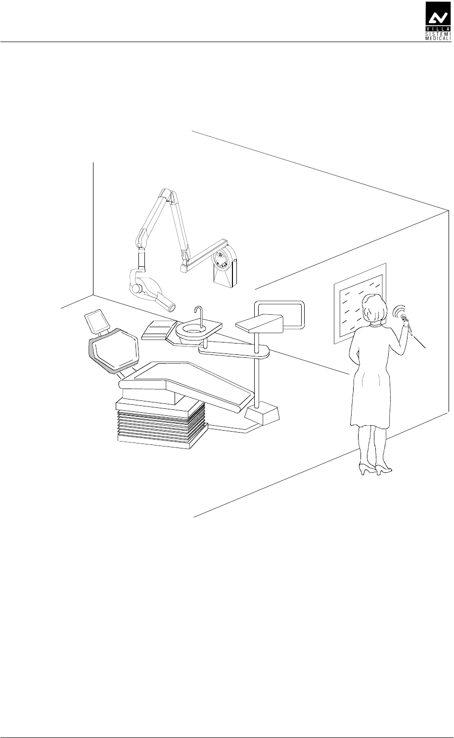
b) During exposure to the rays, the operator must not be in contact
with the tube-head or the collimator cone.
c) During exposure, the operator must maintain a certain distance from
the source of the rays (at least 2 metres) in the opposite direction of
the emission.
d) During exposure, only the operator and the patient may be present
in the room.
e) Use the specific leaded aprons to reduce the undesired effect of
secondary radiations for the patient.

SERVICE MANUAL
Safety aspects
ENDOGRAPH DC (Rev. 1)
10
FEDE
FEDEFEDE
FEDE
Some of the device's components contain material and liquids that, at
the end of the equipment life-cycle, must be disposed of at the recycling
centres appointed by the local health units.
In particular, the device contains the following materials and/or
components:
• Tube-head: non biodegradable plastic materials, glass, dielectric oil,
lead, tungsten, aluminium, copper.
• Other parts of the device: non biodegradable plastic materials,
metal materials, printed circuits, iron-plastic materials.
SERVICE MANUAL
Safety aspects
(Rev. 1) ENDOGRAPH DC
11
C
CC
CD
DD
D
In this manual and on the Endograph DC itself, apart from the
symbols indicated on the keypad, also the following icons are used (see
chapter 6 of User's Manual):
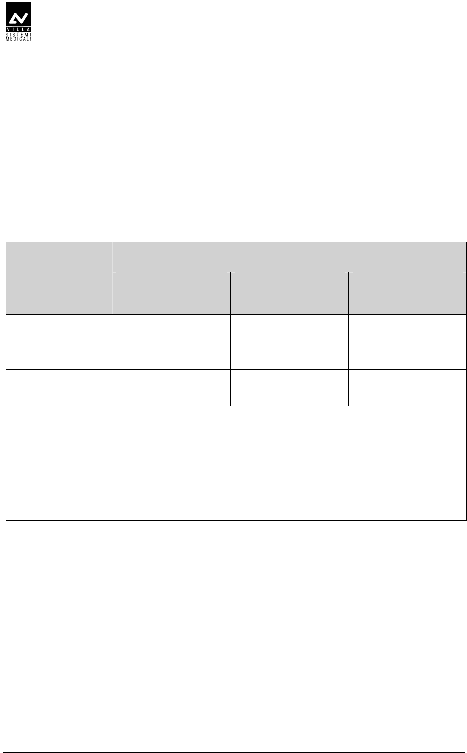
Symbol Description
Device with type B applied parts
In some of its parts, the device contains materials and liquids
that, at the end of the lifespan of the unit, must be disposed of at
the appropriate disposal centres
∼
∼∼
∼ Alternating Current
N Connection point to the neutral conductor
L Connection point to the line conductor
Earth protection
Operation earthing
OFF; device not connected to the mains
ON; device connected to the mains
Exposure enabling key; the exposure enabled status is indicated
by the switching on of the corresponding green symbol
Ray Emission
Focus spot according to IEC 336
Warning: see the accompanying documentation
Product identification code
Serial number
Date of manufacture (year and month)
Manufacturer's name and address
Filtration
Tube-head
X-ray tube
0051 Conformity to the EC 93/42 Directive and subsequent
amendments and additions
0051
Guarantees wireless switch for Endograph DC compliance with
Directive R&TTE 1995/5/EC

SERVICE MANUAL
Description
ENDOGRAPH DC (Rev. 1)
12
CB
CBCB
CB
D
DD
DD
DD
D
4
2
3
1
5
SERVICE MANUAL
Description
(Rev. 1) ENDOGRAPH DC
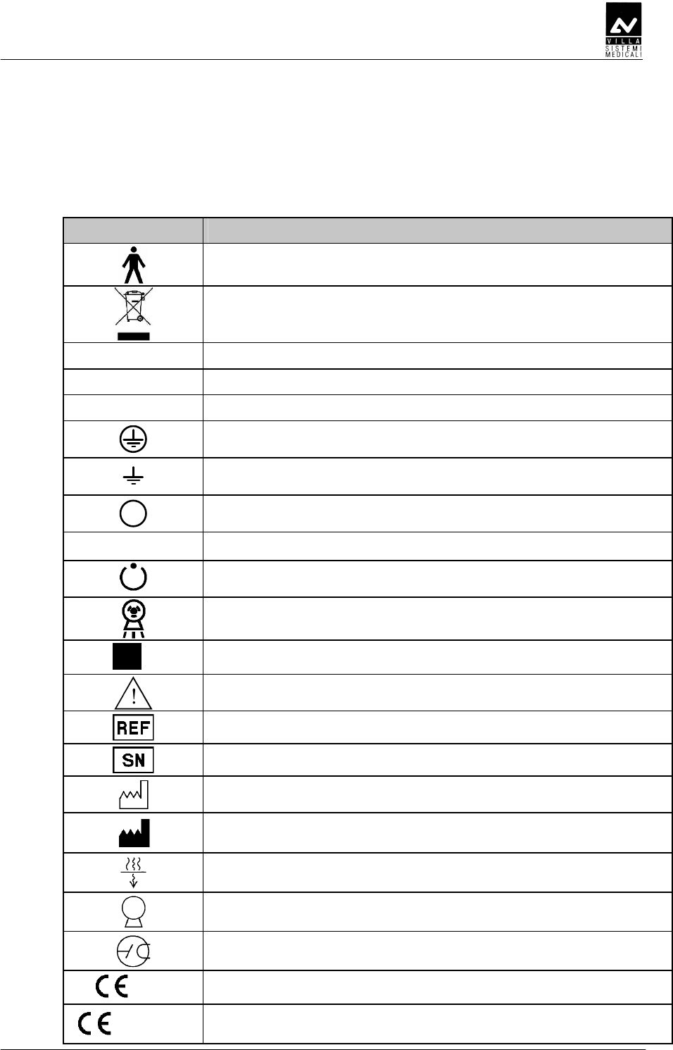
13
1a
Endograph DC plate
1b
Endograph DC plate for
configuration with Wireless X-ray button
2
Tube-head plate
3
DP arm
plate
4
Extension arm
plate
5
WARNING
plate
6
Collimator 30 cm (optional)
plate
7
Wireless X-ray button (optional)
plate
SERVICE MANUAL
Description
ENDOGRAPH DC (Rev. 1)
14
DDE
DDEDDE
DDE
The Endograph DC intra-oral X-ray unit makes it possible to obtain
consistently high quality X-rays thanks to the reproducibility of the unit
parameters with very short exposure times and a very small focus spot.
The Endograph DC intra-oral X-ray unit is compatible for being
combined with digital image acquisition systems, thereby obtaining the
maximum benefits of today's digital intra-oral radiologic technology. If
you do not currently have a digital system, the use of high-speed film or
film in the EKTRASPEED (Kodak) category is recommended in order to
limit the dose absorbed by the patient. A button on the control keypad is
used to select the operating mode and it is possible to select films with
different speeds (sensitivity), the phosphor sensor, the digital sensor or a
customised user mode "Custom mode".
The Endograph DC X-ray unit has an LCD display with dimensions of
84mm x 45mm (240x128 pixel) which makes it easier for the operator to
perform all operations, guaranteeing the immediate and complete display
of the exposure parameters.
The Endograph DC system can use the optional 30 cm collimator cone
(to be ordered separately with code 6159400000). The "long cone
inserted" selection is signalled by the specific symbol on the display. In
this configuration, the exposure times that were pre-set in the anatomic
selection are automatically increased by a multiplicative factor of 2.
The Endograph DC system includes the following: generator, tube-head
complete with collimator, CPU (or logic) card that controls the system
functions, keypad, extension arm and scissors arm.
WARNING:
The Endograph DC system does not automatically detect the presence of
a cone or other item: the operator is responsible for checking the
congruity between the indication on the display and the actual situation
of use.

SERVICE MANUAL
Description
(Rev. 1) ENDOGRAPH DC
15
AEDDADDEE
AEDDADDEEAEDDADDEE
AEDDADDEE
The remote controlled HF generator, together with the tube-head, uses
state-of-the-art microelectronic technology to obtain optimal quality
X-rays while reducing the patient dose of rays. Conventional systems
generally use the intrinsic capacity of the RX generator tube to conduct
the electric current in one direction only. This generates a "train" of RX
impulses. The Endograph DC unit instead uses constant-voltage
technology that generates continuous and stable emission of X-rays.
This reduces the emission of soft rays, guaranteeing the constancy of the
emission parameters, kVp and mA.
The microprocessor-based control ensures constant and repeatable
exposure times; by simply pressing a button it is possible to
automatically select the exposure times based on the size of the patient
and the selected tooth.
DEEE
DEEEDEEE
DEEE
This consists of an arm with a double joint, which permits horizontal
and upward extension. The tube-head remains balanced in all positions.
NOTE:
The scissors arm was designed to work correctly with a maximum
opening angle of 160°; therefore, an opening angle of less than 160° is
required for its use.
A horizontal extension arm can also be added, which is available in
different sizes (30 / 60 / 80 cm) to satisfy all requirements.

SERVICE MANUAL
Description
ENDOGRAPH DC (Rev. 1)
16
D
DD
D
D
DD
D
The tube-head makes it possible to select one of three different high
voltage values: 60 / 65 / 70 kVp.
The radiogenic unit is equipped with a collimator with a focus skin
distance of 20 cm and a ray emission diameter of 6 cm at the cone exit.
The tube-head is connected to the arm by a guide, which permits 390°
horizontal rotation and 290° vertical rotation.
DE
DEDE
DE
The timer consists of an LCD display (240x128 pixel), two LEDs
(yellow: X-rays in progress– green: ready for X-rays) and 5 buttons
that are used to select from among 3 different patient sizes, 3 types
of sensors (film, phosphor or digital) and 7 different pre-set
anatomical structures (incisor, canine, premolar, lower molar,
upper molar, front bite-wing and rear bite-wing).
There are 36 fixed times available for manual selection which vary
from a minimum of 0.01 seconds up to a maximum of 2 seconds.
The timing is managed in order to guarantee exact precision of the
exposure times.
NOTE:
The configuration can be set using the remote X-ray control outside the
examination room. This consists of a wall support onto which the X-ray
button is connected with an extendable cable.
NOTE:
The unit provides two separate contacts for the possible connection with
external signalling devices. One contact signals the status of the unit as
operative and ready to be used, the second emits the X-rays. The
connection methods and the requirements necessary for the signalling
devices are described in the "Service Manual".
SERVICE MANUAL
Description
(Rev. 1) ENDOGRAPH DC
17
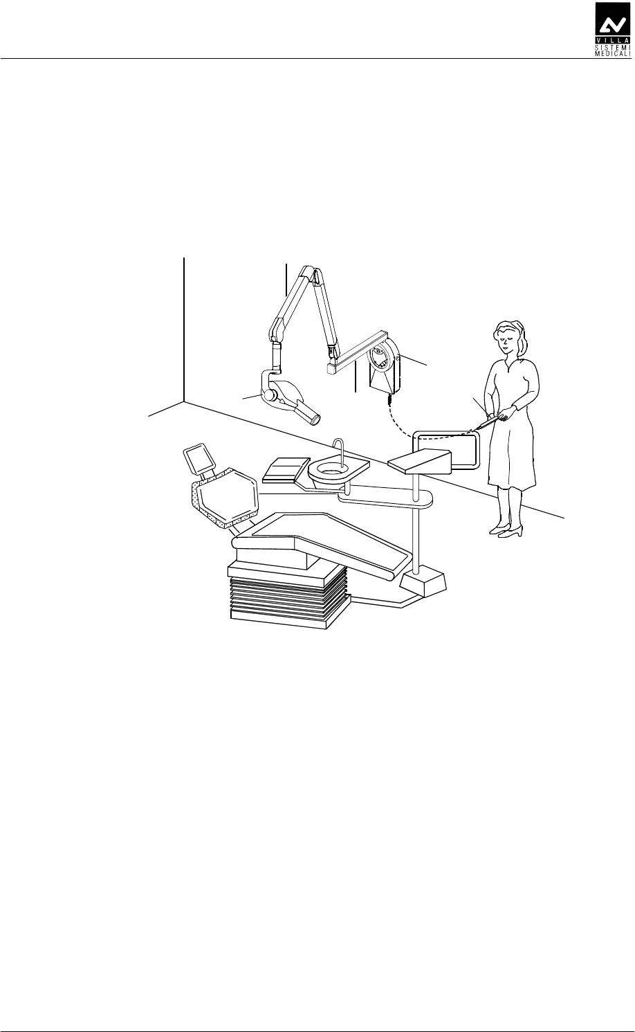
BE
BEBE
BE
CEE
CEECEE
CEE
Figure 3-1
1 Tubehead
2 Scissors arm
3 Extension arm
4 Timer
5 X-ray button
1
2
3
4
5
SERVICE MANUAL
Description
ENDOGRAPH DC (Rev. 1)
18
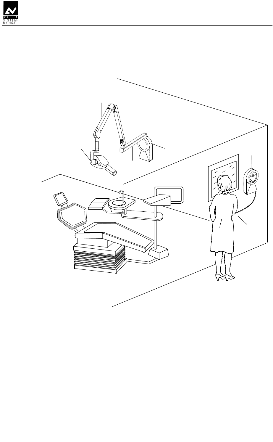
DDDEE
DDDEEDDDEE
DDDEE
Figure 3-2
1 Tubehead
2 Scissors arm
3 Extension arm
4 Wall support
5 Remote timer
6 X-ray button
5
6
1
2
3
4
SERVICE MANUAL
Description
(Rev. 1) ENDOGRAPH DC
19
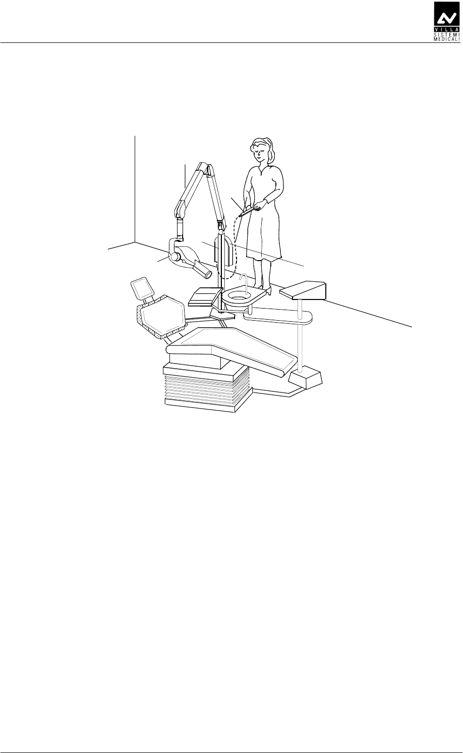
DE
DEDE
DE
Figure 3-3
1 Tubehead
2 Scissors arm
3 Mobile stand
4 Timer
5 X-ray button
1
2
5
3
4
SERVICE MANUAL
Description
ENDOGRAPH DC (Rev. 1)
20
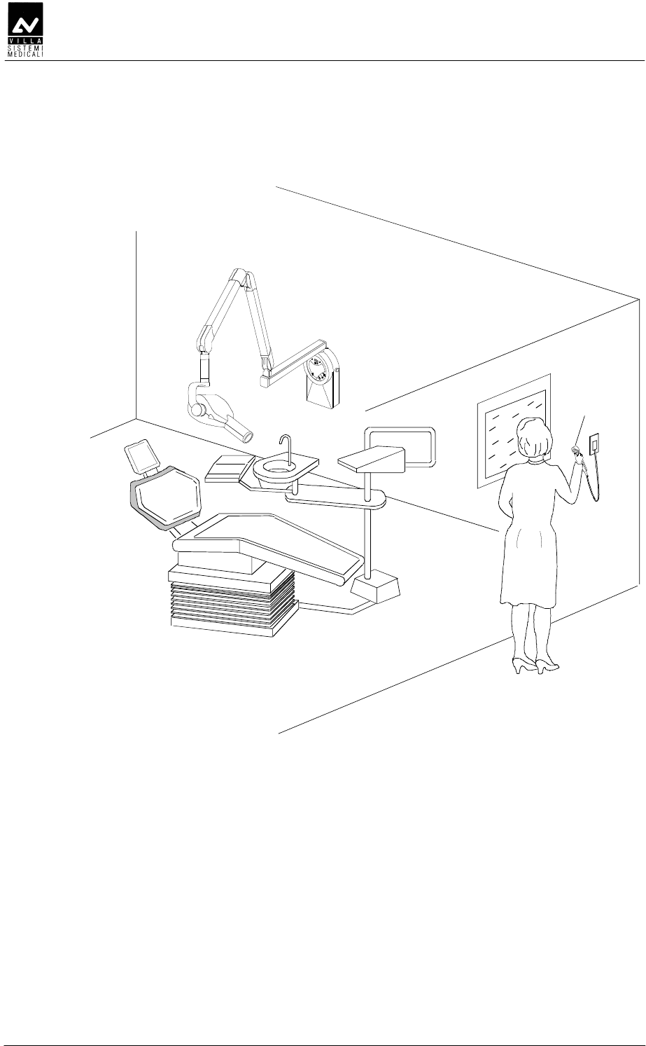
DD
DDDD
DD
EE
EEEE
EE
1
Figure 3-1
1 Remote X-ray button (optional)
SERVICE MANUAL
Description
(Rev. 1) ENDOGRAPH DC
21
BEEDD
BEEDDBEEDD
BEEDD
E
EE
E
1
Figure 3-2
1 Wireless X-ray button (optional)
SERVICE MANUAL
Technical data
ENDOGRAPH DC (Rev. 1)
22
BAB
BABBAB
BAB
Technical characteristics
Equipment Endograph DC
Manufacturer VILLA SISTEMI MEDICALI
Buccinasco (MI) Italia
Class Class I with type B applied parts
(according to EN 60601-1
classification)
Protection degree IPX0 standard device
Line voltage 99-264 V∼
Rated voltage 110-240 V∼
Line frequency 50 / 60 Hz
Maximum line current 5.2 A rms impulsive
@ 115 V ∼
2.5 A rms impulsive
@ 230 V ∼
Technical factors for maximum line
current
70kV, 6mA
Absorbed power 583W (584VA) 566W (570VA)
Maximum apparent line resistance 0.4 Ω (99-132 V∼) 0.8 Ω (198-264 V∼)
Mains fuse 6.3 AT
Selectable times from 0.01 to 2.00 s in 36 steps
Automatic selection 882 pre-programmed times (7 anatomic -
3 sizes - 3kV - 2 SID- 3 receptors)
Time accuracy ± 5 % ± 2 ms
High voltage values 60-65-70 kVp selectable
Tubehead current 6 mA
kV accuracy ± 8 % @ rated voltage
Tubehead anodic current accuracy ± 10 % @ rated voltage
Maximum exposure time 2.0 s
Timer size 284×253×123.3 mm

SERVICE MANUAL
Technical data
(Rev. 1) ENDOGRAPH DC
23
Tube-head characteristics
Manufacturer CEI Bologna (Italy)
Rated voltage 60-65-70 kV
p
(selectable)
Tubehead power 420 W
Total filtration ≥ 2.5 mm Al eq. @ 70 kV
HVL (Half value Layers) > 2 mm Al eq.
Transformer insulation Oil bath
Interval between the exposures /
duty cycle
60 times the X-ray time/
1 : 60
Focus size 0.5 (IEC 336)
Minimum focus to skin distance 20 cm (optional 30 cm cone)
X-ray diameter (@ 20cm focus) ≤ 6 cm (35x45 mm + 25x35 mm +
20x30 mm optional)
Cooling Convection
Leakage radiation at 1 metre < 0.25 mGy/h
Technical factors for leakage radiation 70 kV, 6 mA, 1 s duty cycle
1 exposure every 60 seconds
X-ray tube characteristics
Manufacturer CEI Bologna (Italy)
Type OX/70-5
Inherent filtration 0.5 mm Al equivalent to 70 kV
Anode tilt angle 19°
Anode material Tungsten
Rated voltage 60-65-70 kV (selectable)
Filament max voltage 3.1 V
Filament max current 2 A
Anode thermal capacity 7 kJ
Anode cooling capacity (max) 110 W

SERVICE MANUAL
Technical data
ENDOGRAPH DC (Rev. 1)
24
Environmental conditions
Operating temperature range +10°C ÷ +40°C
Relative working humidity (RH) range 30% ÷ 75%
Temperature range for transport and
storing
-20°C ÷ +70°C
Humidity range for transport and
storing
<95 % non-condensing
Minimum atmospheric pressure for
storing and transport
630hPa
Weight of the unit and the removable parts
Gross weight including packaging 30 kg
Net weight of the unit in the standard
configuration
23 kg
Extension arm 60 cm (standard) 2.9 kg
Extension arm 80 cm 3.5 kg
Extension arm 30 cm 1.9 kg
Scissors arm with tube-head support 10 kg
Timer + wall support 5.05 kg
Tube-head 5 kg

SERVICE MANUAL
Technical data
(Rev. 1) ENDOGRAPH DC
25
DEDEDE
DEDEDEDEDEDE
DEDEDE
The measuring method with non-invasive instruments, for example
kV
p
/t meter, is accepted, even if it generally provides less accuracy. In
fact, the measurement of the high voltage at the tube with non-invasive
instruments is closely correlated to the method selected by the
instrument manufacturer; in general, this method is more inaccurate
than the direct method and may also require two subsequent exposures.
In the same way, the method of measuring the anodic current with the
indirect method is affected by systematic errors, as they are often based
on the measurement of the current/time product, dividing the
measurement by the time measured with the said method.
• AFDFDDD
AFDFDDDAFDFDDD
AFDFDDD
The kVp value is defined as the stationary value of the high voltage
applied at the tube that is stabilised under load after the pre-heating
time.
Measure the value of the kVp with a non-invasive instrument (with
2% accuracy), setting the exposure time to 1 second.
• DEDDEDD
DEDDEDDDEDDEDD
DEDDEDD
The exposure time must be measured using a non-invasive
instrument.
In compliance with standard IEC 60601-2-7, the exposure time is
measured as the interval of time between the moment in which the
high voltage has reached for the first time a value equal to 75% of
the peak value and the moment in which it goes down below this
value.
SERVICE MANUAL
Technical data
ENDOGRAPH DC (Rev. 1)
26
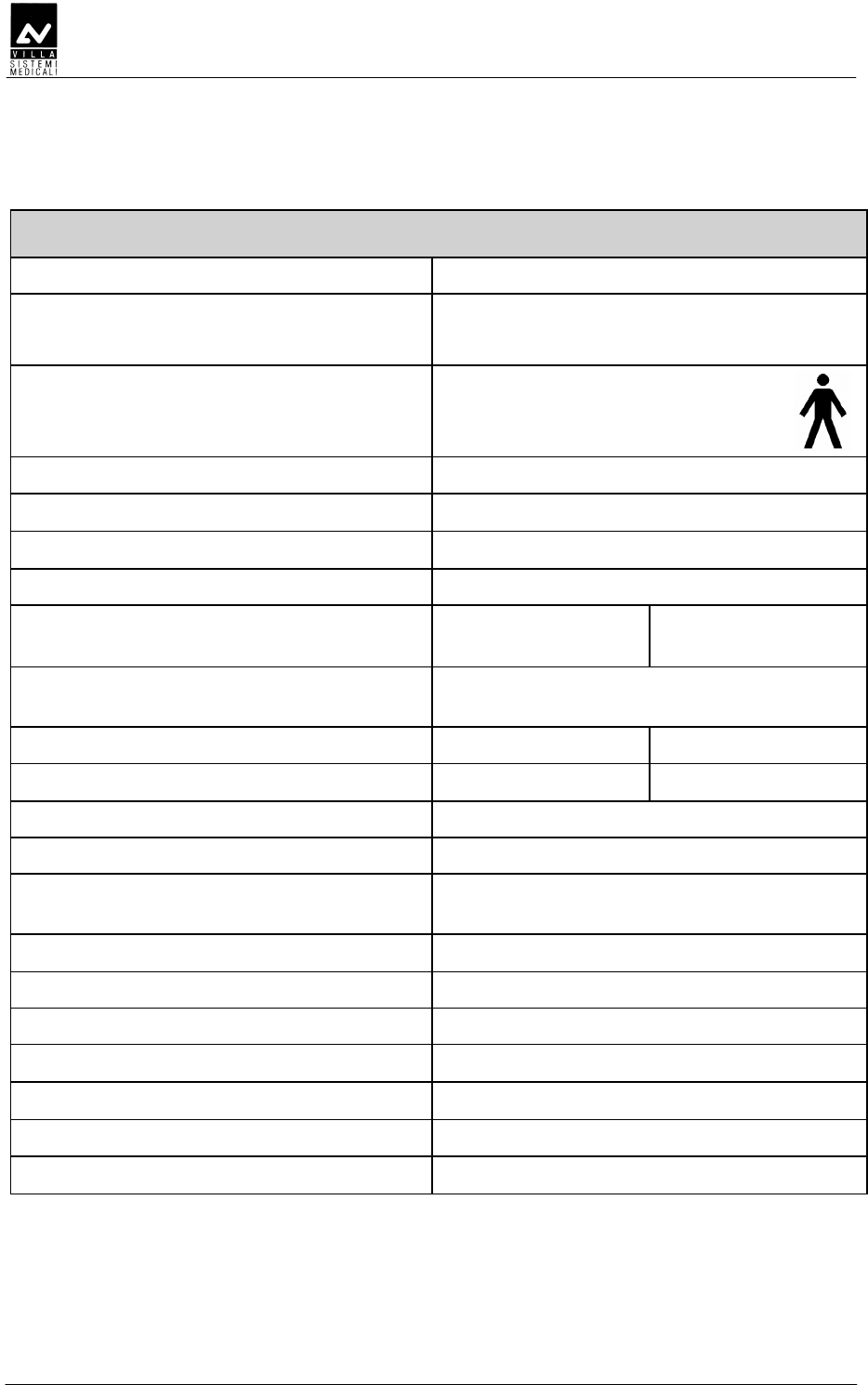
BEFDDDED
BEFDDDEDBEFDDDED
BEFDDDED
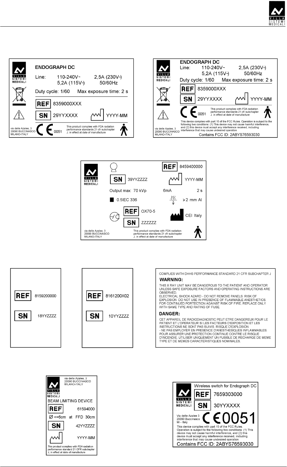
OX/70-5
Emission characteristics Filament characteristics
Load
SERVICE MANUAL
Technical data
(Rev. 1) ENDOGRAPH DC
27
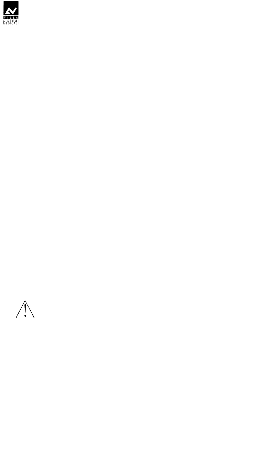
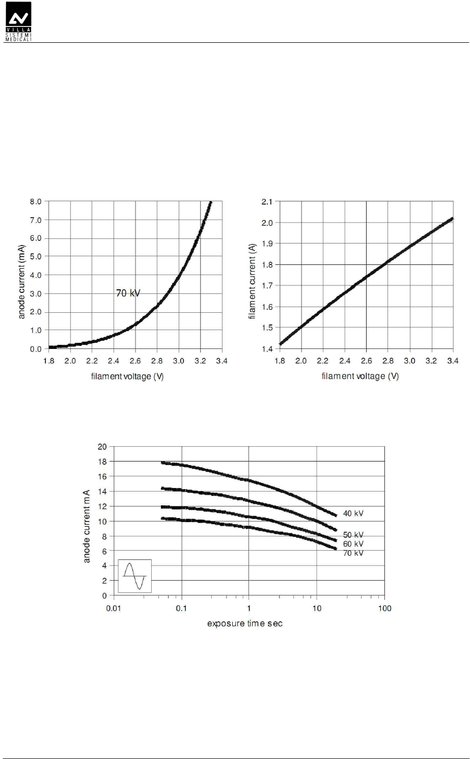
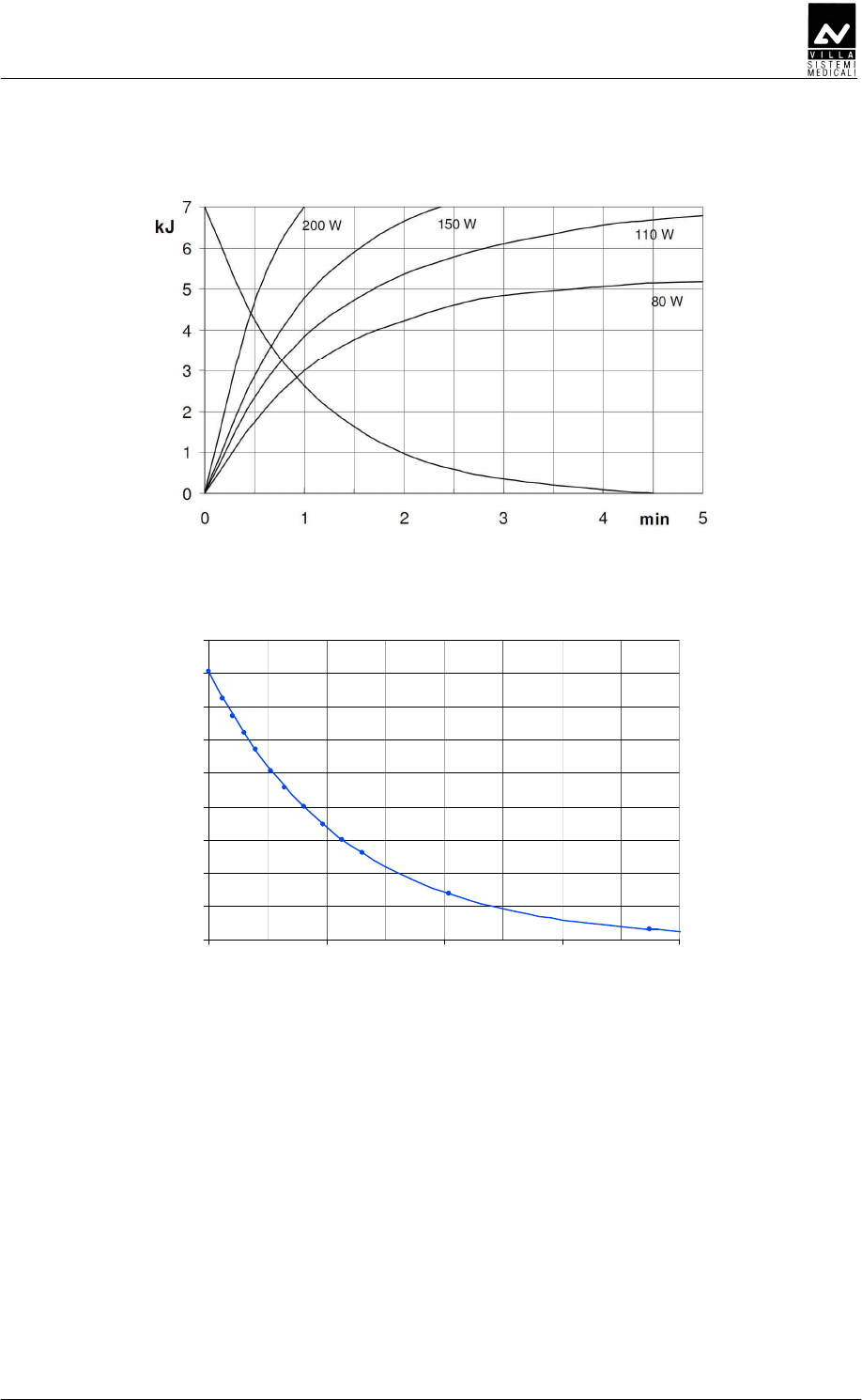
Anode cooling curve
Curv a raffre ddame nto monoblocco
0
10
20
30
40
50
60
70
80
90
0 100 200 300 400
Time [min]
E [kJ]
Tube-head cooling curve

SERVICE MANUAL
Technical data
ENDOGRAPH DC (Rev. 1)
28
DDEDDE
DDEDDEDDEDDE
DDEDDE
Endograph DC complies with the following standards:
IEC 60601-1:1988 + A1:1991 + A2:1995
Medical Electrical Equipment – Part 1: General requirements for safety.
IEC 60601-1-6:2004
Medical electrical equipment - Part 1: General requirements for safety -
collateral standard: Usability.
IEC 60601-1-2:2001+ A1
Electromagnetic Compatibility Requirements and Tests.
IEC 60601-1-3:1994
Gen. Requirements for Radiation Protection in Diagnostic X-ray
Equipment.
IEC 60601-2-7:1998
Particular requirements for the safety of high-voltage generators of
diagnostic X-ray generators.
IEC 60601-2-28:1993
Particular requirements for the safety of X-ray source assemblies and
X-ray tube assemblies for medical diagnosis.
IEC 62304:2006 + Ac:2008
Medical device software - Software life-cycle processes.
ISO 14971:2007
Medical Devices - Application of Risk Management to Medical Devices.
CAN/CSA C22.2 No. 601.1-M90 (2nd edition) +A1 + A2
Medical Electrical Equipment - Part 1: General Requirements for Basic
Safety and Essential Performance
UL 60601-1 (1st edition)
Medical Electrical Equipment - Part 1: General Requirements for Safety
0051 Guarantees Endograph DC compliance with Directive
93/42 and as amended. (subsequent amendments and
additions)
CFR 21
Code Federal Regulation. Sub Chapter J
Canadian Medical Device Regulations

SERVICE MANUAL
Technical data
(Rev. 1) ENDOGRAPH DC
29
DDEDDEEDD
DDEDDEEDDDDEDDEEDD
DDEDDEEDDEDD
EDDEDD
EDD
Endograph DC contains radio module with FCC ID: 2ABYS76593030
The wireless switch for Endograph DC complies with the following
standards:
ETSI EN 300 220-2 v.2.3.1
ETSI EN 301 489-3 v.1.4.1
Electromagnetic Compatibility and Radio Spectrum matters (ERM).
0051
Guarantees wireless switch for Endograph DC
compliance with Directive R&TTE 1995/5/EC
CFR title 47 part 15
Subpart C-Intentional Radiators 15.231
Changes or modifications not expressly approved by the manufacturer
could void the user’s authority to operate the equipment.
This device complies with part 15 of the FCC Rules. Operation is subject
to the following two conditions: (1) This device may not cause harmful
interference, and (2) this device must accept any interference received,
including interference that may cause undesired operation.
SERVICE MANUAL
Technical data
ENDOGRAPH DC (Rev. 1)
30
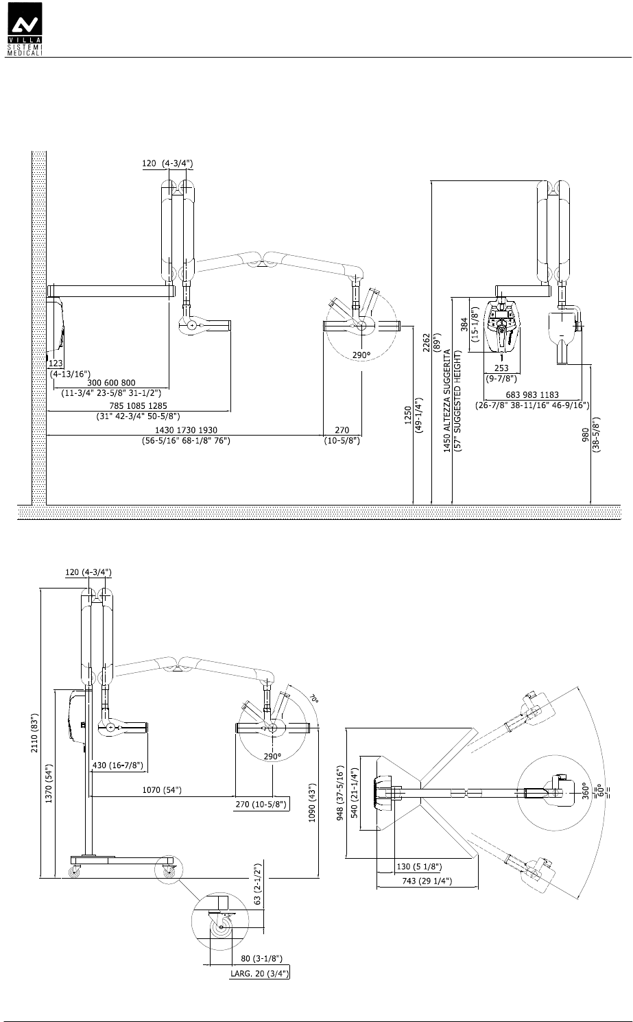
D
DD
D
ABC
Figure 4-1: Dimensions of the wall version
Figure 4-2: Dimensions of the mobile stand version
SERVICE MANUAL
Pre-installation
(Rev. 1) ENDOGRAPH DC
31
C
CC
C
Endograph DC does not ask for special pre-installation works, still it is
necessary to grant an adequate grounding for EMC compatibility and
safety.
Section of grounding cable must be at least equal of greater than the
section of line cables. It is advisable to use a grounding cable with
section 2.5mm².
If cables are going to be positioned inside the wall, it is better that ducts
are already positioned, taking into account where the device will be
installed, taking care that cables exit in correspondence of the hole on
the lower side of the wall plate.
The Manufacturer can assist technically in the pre-installation phase,
but preparation works are a customer’s responsibility.
D
DD
D
NOTE:
This chapter is valid for Wall version. The user does not need to assess
the consistency of the wall for Stand version.
The installer is responsible for assessing the consistency of the wall.
The extraction load on each screw is 446 N (46 kg) for the wall version
standard assembly (3 mounting screws), 634 N (65 kg) for the wall
version "single stud" assembly (5 mounting screws).
For each type of wall use the appropriate mounting method complying
with the following specifications which guarantee a safety factor 4:
• Wooden uprights: self-threading screws 8x70 A 4.8 (provided with
the installation kit)
• Full or concrete bricks: screw anchors (provided with the installation
kit) in cast iron M8 or chemical screws WURTH (not provided)
• Hollow bricks: chemical screws (not provided).
A counter-plate must be used with walls with a lower resistance.
WARNING:
The Manufacturer is not responsible for any installations that do not
comply with the specifications stated above.
SERVICE MANUAL
Pre-installation
ENDOGRAPH DC (Rev. 1)
32
DEED
DEEDDEED
DEED
D
DD
D
• Single-phase supply + ground 110-240 V∼ ±10%
• Frequency 50 – 60 Hz
• Max absorbed current during emission 5.2 A rms impulsive @ 115 V∼
2.5 A rms impulsive @ 230 V∼
• Apparent line resistance 0.4 Ω @ 99-132 V∼
0.8 Ω @ 198-264 V∼.
NOTE:
The device is intended for permanent installation.
It is forbidden to connect the system by a plug in a wall socket for
safety reasons.
Mobile version has to be requested on order and it is not possible to
transform wall mounted version into a mobile version in field.
NOTE:
A circuit breaker with overcurrent protection must be connected to the
intraoral X-ray equipment with the following features:
–
Nominal current: 10A
–
Differential sensitivity: 0.03A.
Section of line cables must be not lower than 1.5 mm².
Grounding of the system must meet requirement of the laws; a bad
grounding can be dangerous for the operator and can generate
malfunctioning of the device.
NOTE:
The mobile stand is supplied without the mains plug to permit the free
connection at every socket.
Is in charge to the installer supply a mains plug compatible with the
local electrical network with follow features: connection 2P+Earth
protection, minimum working voltage compliant with the power
supply in use, minimum rated current 10A.
Then install the mains plug on the cable by connecting the Y/G wire in
the earth protection connector and the others conductors in the others
free connectors.
The mains plug must be in compliance with the laws and directive in
force of the Country of use and report at least one quality/safety
mark released by a recognized Notified Body.
NOTE:
Endograph DC can be connected to signaling devices outside the
installation room; please make reference to chapter 6.4.1.
It is also possible to mount the system with remote keyboard: in
this case it is necessary to use a RJ45 cable provided by the
Manufacturer.

SERVICE MANUAL
Installation
(Rev. 2) ENDOGRAPH DC
33
C
CC
C
Endograph DC intraoral X-ray equipment is shipped pre-assembled in
sub-assys.
Mechanical assembly work consists solely in assembling these units.
All the mechanical components are therefore adjusted before delivery;
not only is there no need to carry out any adjustment on these parts but
it would also cause the equipment to malfunction; any adjustment must
be carried out by authorised personnel only.
SERVICE MANUAL
Installation
ENDOGRAPH DC (Rev. 2)
34
DEDEE
DEDEEDEDEE
DEDEE
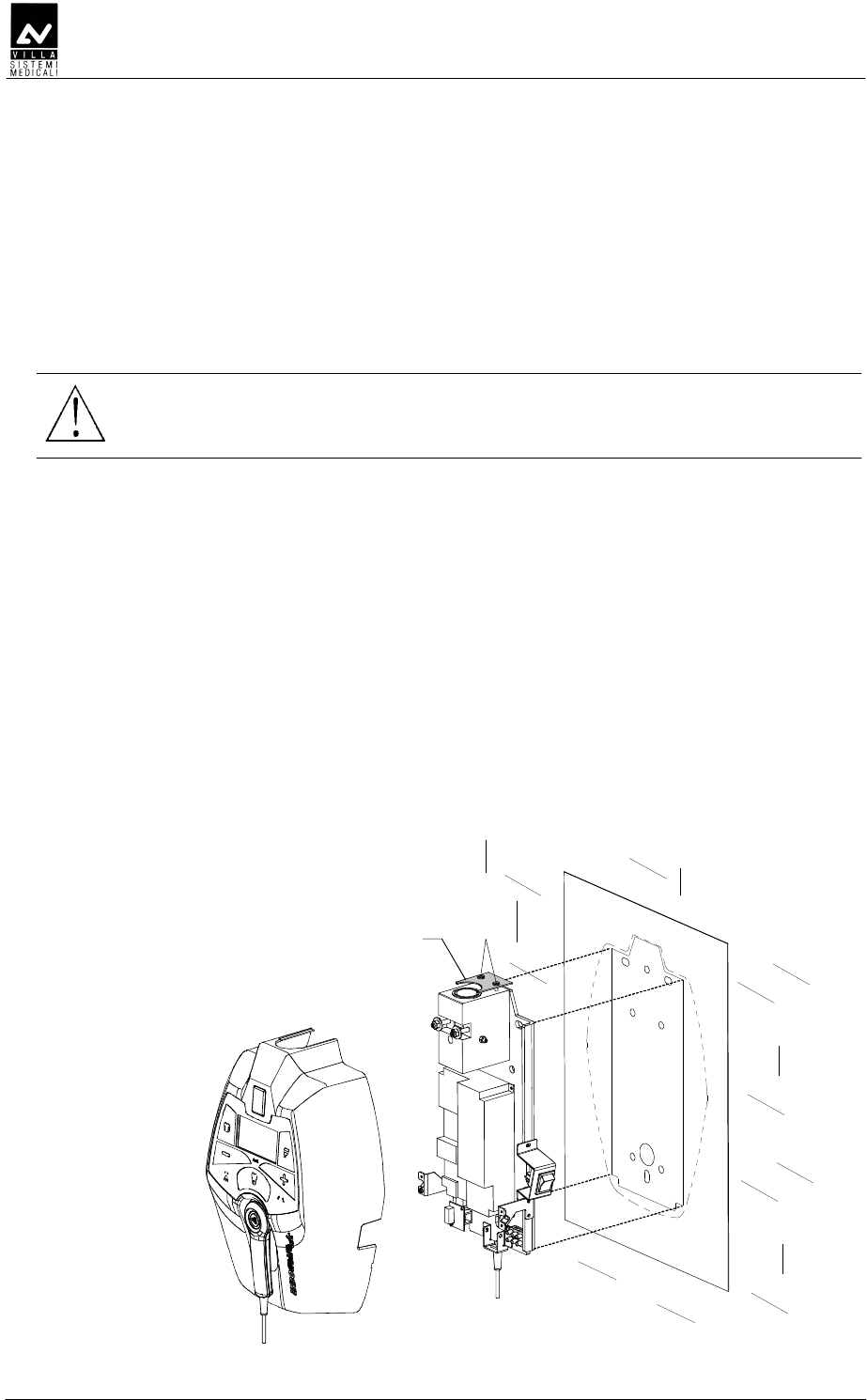
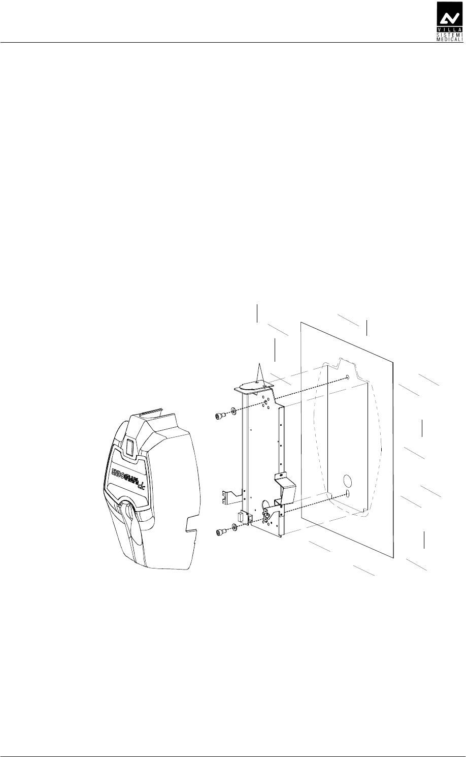
1. To be sure that the equipment is in the correct position we
recommend you put the provided template code 39599100 (3 -
Figure 6-1) in the requested position, in this way identifying the
requested wall-mounting position. Considering the overall
dimensions of the equipment, put the top part of the template at
1450 mm from the floor.
WARNING:
The installer will assess the consistency of the wall taking into
consideration the screw extraction load specified in paragraph 5.1.
2. Mark the mounting points and make the respective holes with a
diameter corresponding to the chosen screws.
Making reference to the template, use holes "A" for standard
installation. Use holes "B" for single stud installation.
3. Remove the plastic timer cover (1 - Figure 6-1) loosening the two
sealing screws (2 - Figure 6-1) placed on the top part.
Do not remove completely the screws and the relevant plate (4 -
Figure 6-1); with the extention arm in place, will not be possible
to reassemble the plate.
To make the operation easier, disconnect all wires between wall plate
and cover.
4. Fix the timer to the wall using the relevant screws verifying the
perpendicularity of both axes with respect to the wall.
A
A
A
B
B
B
B
B
2
3
1
4
Figure 6-1
SERVICE MANUAL
Installation
(Rev. 2) ENDOGRAPH DC
35
DDDDE
DDDDEDDDDE
DDDDE
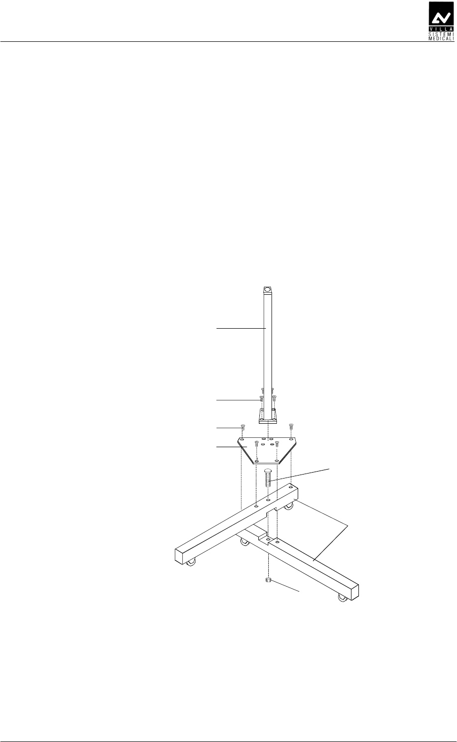
1. Cross the two base tubes (1 - Figure 6-2) into the provided cut, fixing
them together with the screw (2 - Figure 6-2) and relevant nut (3 -
Figure 6-2). Do not tighten the screw completely.
2. Position the base plate (4 - Figure 6-2) and fix it with the four screws
(5 - Figure 6-2). If necessary, reposition the two base tubes (1 -
Figure 6-2) slightly in order to align the relevant holes on the plate.
3. Lock the nut (3 - Figure 6-2) in order to block the base tubes (1 -
Figure 6-2) permanently.
4. Assemble the stand column (6 - Figure 6-2) on the base plate (4 -
Figure 6-2) with the four screws (7 - Figure 6-2).
1
2
4
5
6
7
3
Figure 6-2
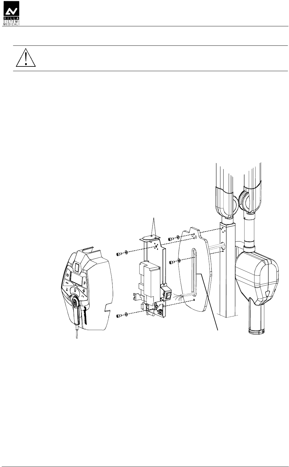
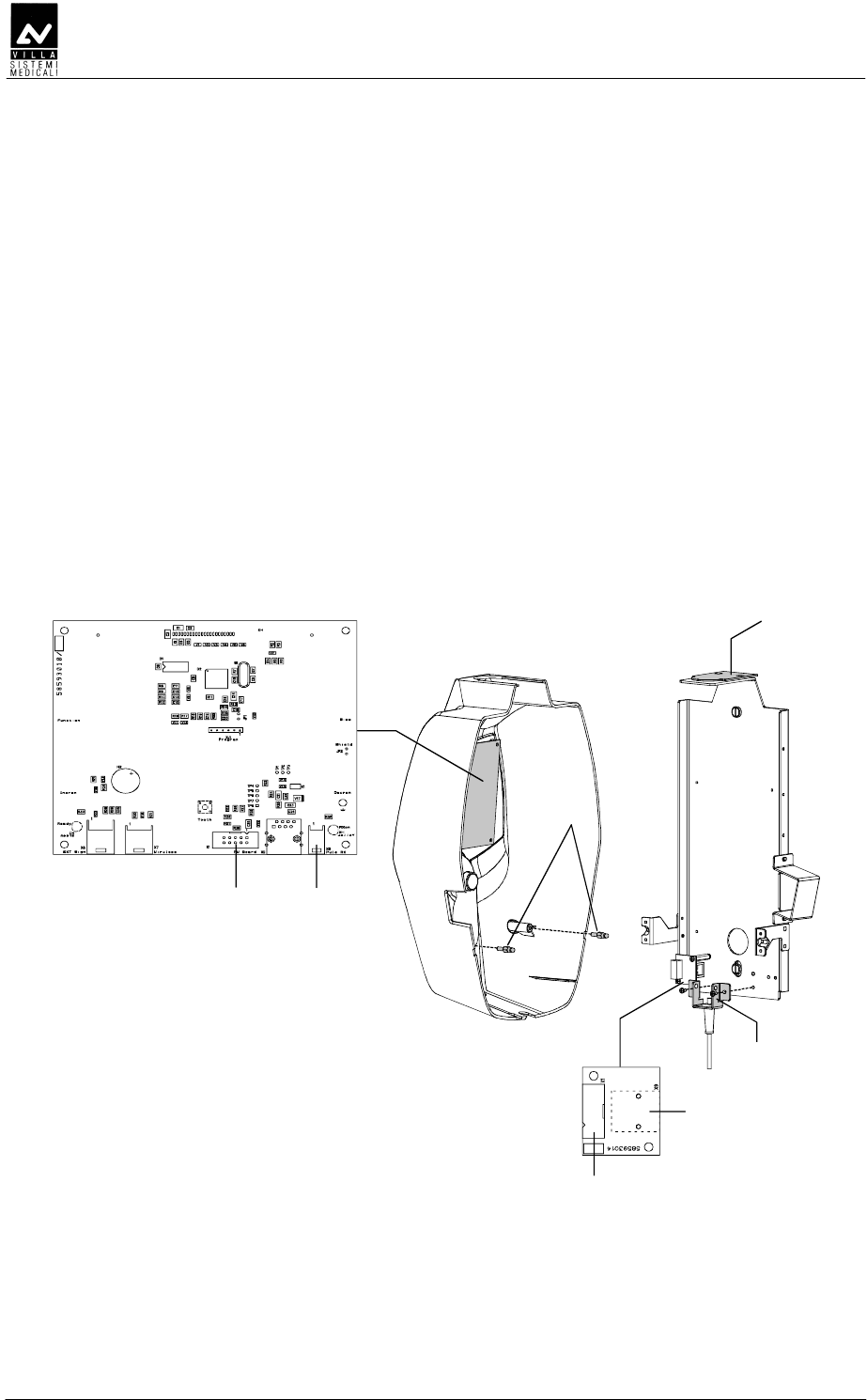
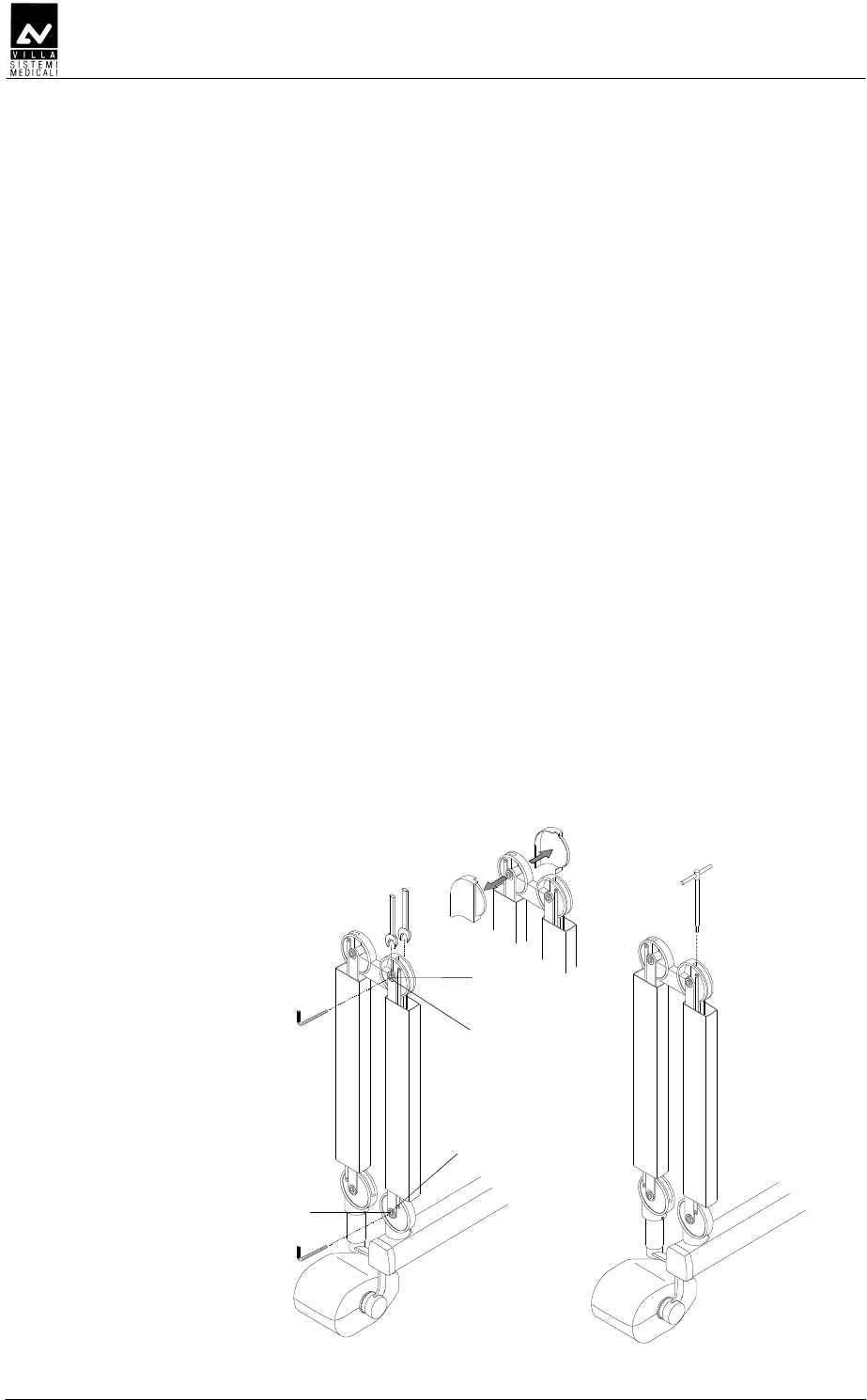
5. Assemble the timer support plate (8 - Figure 6-3) to the stand
column, fixing it with the two screws (9 - Figure 6-3) present on the
stand column.
SERVICE MANUAL
Installation
ENDOGRAPH DC (Rev. 2)
36
WARNING:
The timer must be fixed to the support plate after assembling the
scissors arm (see paragraph 6.3.3).
6. Remove the plastic timer cover (10 - Figure 6-3) by loosening the two
sealing screws (12 - Figure 6-3) placed on the top.
To make the operation easier, disconnect all cables connecting the
timer and the plastic cover.
7. Fix the timer onto the support plate with the two screws (14 - Figure
6-3) taking care to thread the supply cable and the cables coming
from the scissors arm inside the hollow one (15 - Figure 6-3). Check
that the upper level is level using a bubble level.
10
8
15
12
9
9
14
14
Figure 6-3

SERVICE MANUAL
Installation
(Rev. 2) ENDOGRAPH DC
37
DDE
DDEDDE
DDE
DDDDE
DDDDEDDDDE
DDDDE
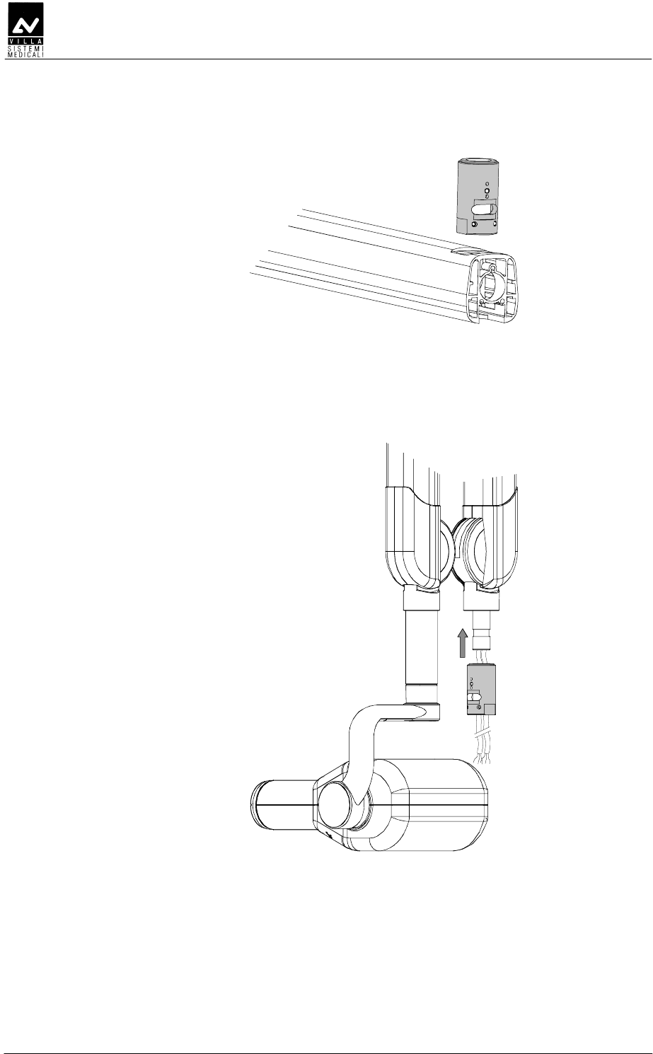
1. Insert the extension arm into the arm support block which is an
integral part of the wall support plate.
NOTE:
You must keep the arm orthogonal to the plate to be able to insert the
shaft into the bush placed inside the support.
2. Assemble the extension arm frictioning mechanism block (1 – Figure
6-4); this frictioning mechanism (code 6159300100) is included in
the mounting hardware packaging.
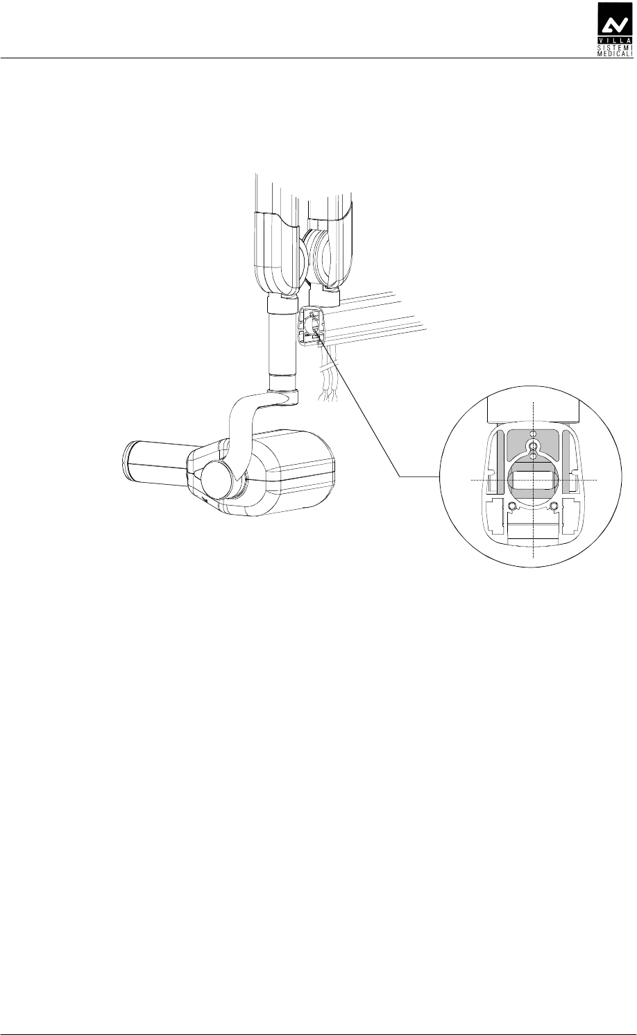
3. Assemble the arm rotation stop screw (2 - Figure 6-4) in the hole
present on the shaft; this screw (code 2100014800) is included in
the mounting hardware packaging.
4. Tighten the two lateral screws (3 - Figure 6-4 – one on each side)
ensuring that they block the arm rotation without interfere with the
extension arm pin.
SERVICE MANUAL
Installation
ENDOGRAPH DC (Rev. 2)
38
NOTE:
The purpose of the frictioning mechanism and the rotation stop pin is to
prevent the extension arm from becoming detached.
1
2
3
Spring washers
sequence
Figure 6-4
SERVICE MANUAL
Installation
(Rev. 2) ENDOGRAPH DC
39
DDEEE
DDEEEDDEEE
DDEEE
NOTE:
To help assembly Endograph DC is shipped with the tubehead already
mounted on the scissors arm; it is recommended to let the tape wrapping
the arm in place. In case it is removed, besides making more difficult the
assembly it is possible that the installer is hurt or the arm damaged.
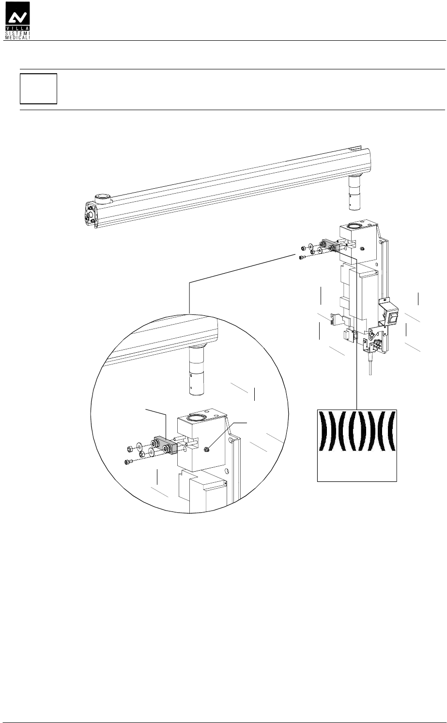
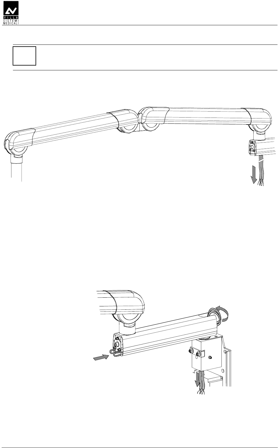
1. Remove the friction group fixing plate fixed to the extension arm with
three screws (scissor arm side). Take note that the upper screw is
shorter than the other two and has to be mounted in the same
position.
Friction group
Fixing plate
Figure 6-5
2. Remove also the friction taking care not to loose the spring washer.
Here following is indicated the right sequence of the washers.
Spring washer
sequence
Figure 6-6
SERVICE MANUAL
Installation
ENDOGRAPH DC (Rev. 2)
40
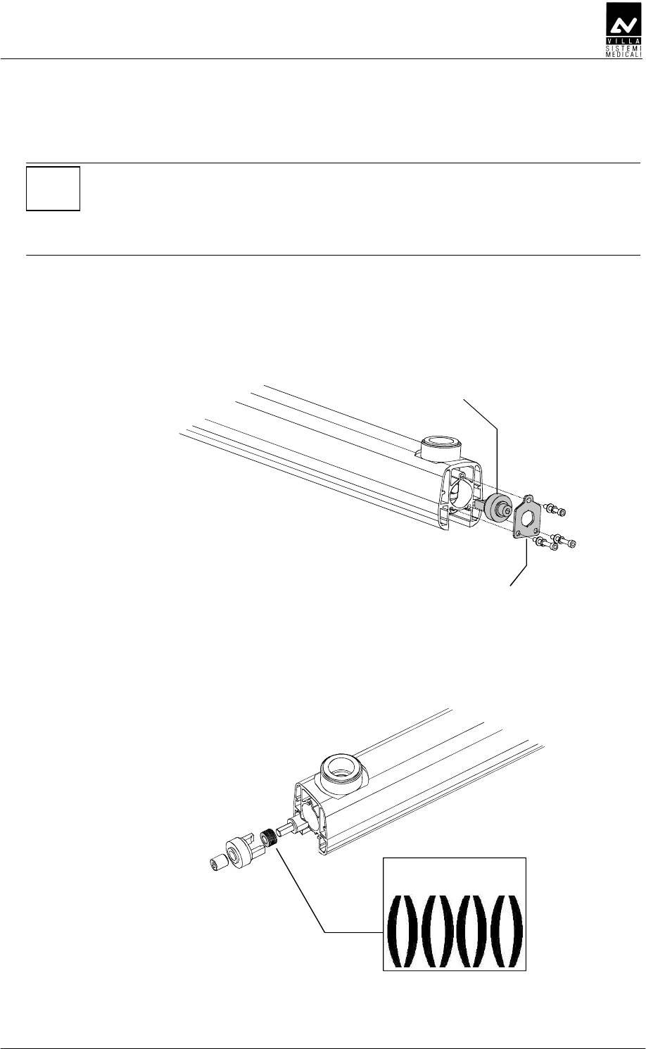
3. Remove the fixing bushing. This operation will permit an easier
insertion of the scissor arm group into the extension arm.
Figure 6-7
4. Insert the extension arm pin in the bushing; during insertion take
care to the O-Rings present in the bushing. The friction group fixing
holes must be toward tube head support.
Figure 6-8
SERVICE MANUAL
Installation
(Rev. 2) ENDOGRAPH DC
41
5. Insert the scissor arm into the extension arm, aligning the bushing
fixing holes to the extension arm screws. Power cable, signal cable
and grounding cable must be let out freely from the extension arm.
Figure 6-9
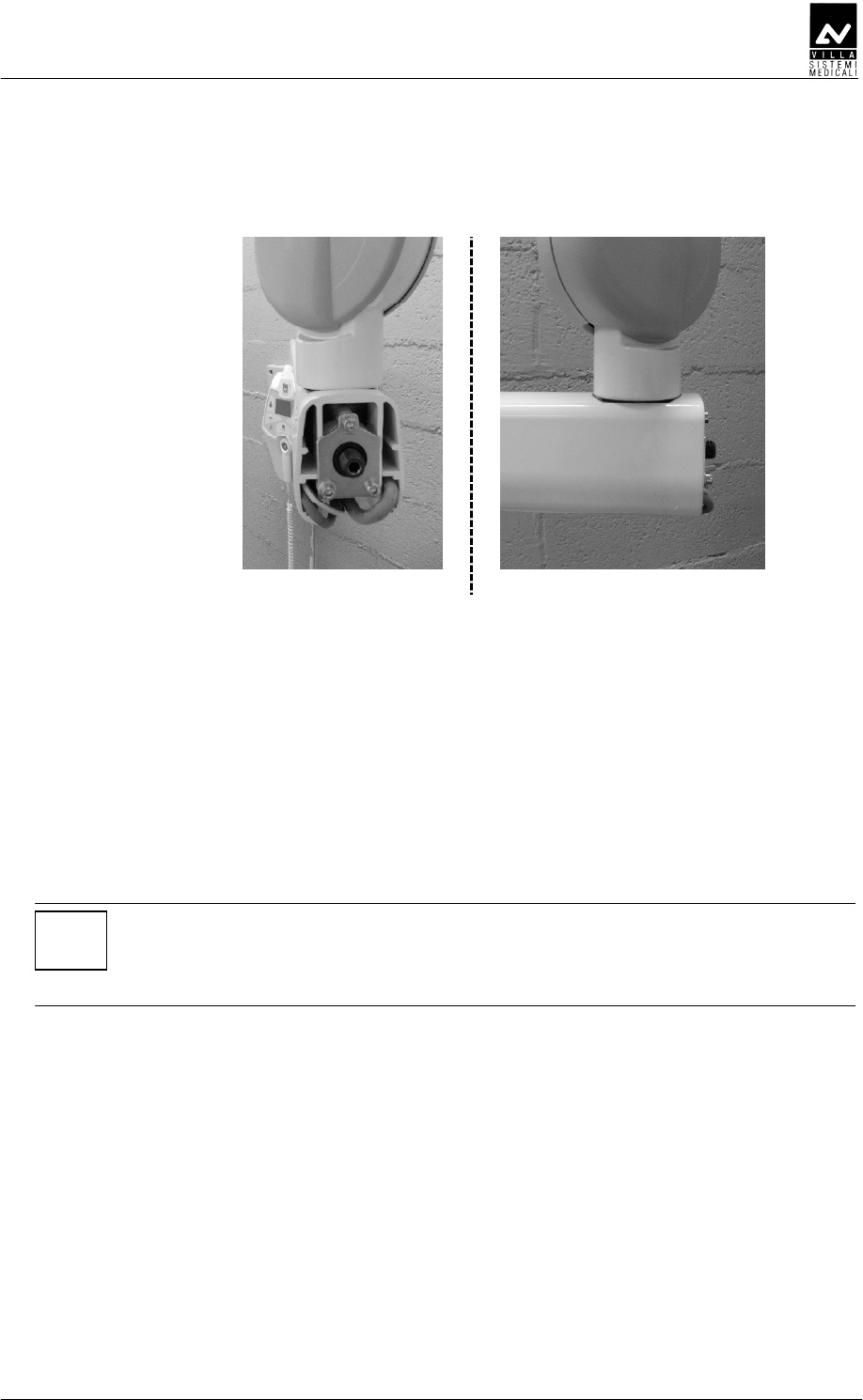
6. Mount the friction group and fix the plate using the shorter screw in
the top hole (Figure 6-5). Tighten the grub screw until it is frictioned
but don't force the friction. It has to be adjusted only if necessary.
7. Remove the safety clamp and completely open the scissors arm to
locate the position where the cable is more recovered inside the arm
itself.
SERVICE MANUAL
Installation
ENDOGRAPH DC (Rev. 2)
42
NOTE:
The following operations must be done with the scissors arm completely
open.
8. Holding this position, gently pull the cables coming from the scissors
arm down to avoid excess cable in the arms.
Figure 6-10
9. Insert the cables inside the extension arm (power cable on one side
and filament cable and the grounding cable on the other side)
following the drawing in Figure 6-11 (fase 1); this will make sure that
the cables are not tensioned during use. To make this easier, wrap
together the grounding and filament cables with tape.
10. Run the cables inside the extension arm until they come completely
out at the opposite end.
11. Insert the cables inside the rotation pin as shown in the following
figure (fase 2 and 3).
1
2
3
Figure 6-11
SERVICE MANUAL
Installation
(Rev. 2) ENDOGRAPH DC
43
12. Push the cables inside the extension arm (scissors arm side), so that
no excess is left at the extremity. When doing this, firmly pull the
cables on the other end of the extension arm (timer side).
Front view
Lateral view
Figure 6-12
13. Make sure that cables don't push the end cap when opening and
closing the scissors arm. Repeat this operation several times in all
the arm positions.
If necessary, repeat step 12 and carefully adjust the excess cable.
14. Check that the DP arm is perfectly inserted; check that the rotation
of the scissors arm inside the extension arm is the one ergonomically
requested by the operator, otherwise work on the frictioning
mechanism (1 - Figure 7-2) until you get the requested run.
NOTE:
This frictioning mechanism is also used to prevent the scissors arm from
becoming detached and for this reason it must never be loosened
completely.
15. Check the ergonomics of the arm opening movement, otherwise
adjust the tension of the arm balance springs (see paragraph 7.1.3).
16. Assemble the front covers of the extension arm included in the
mounting hardware packaging.
SERVICE MANUAL
Installation
ENDOGRAPH DC (Rev. 2)
44
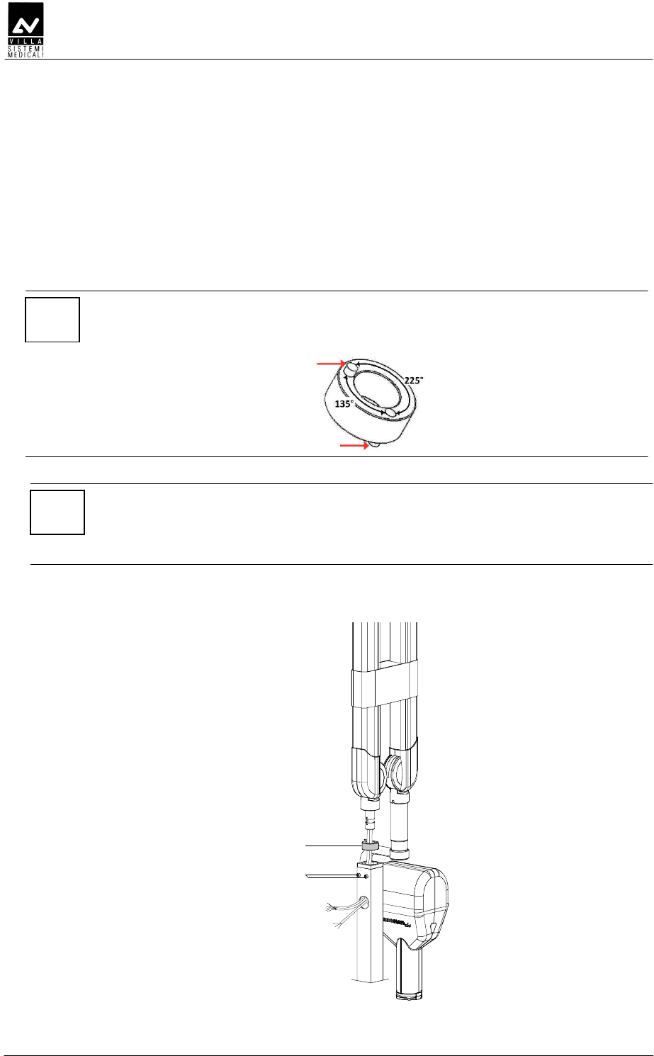
DDED
DDEDDDED
DDED
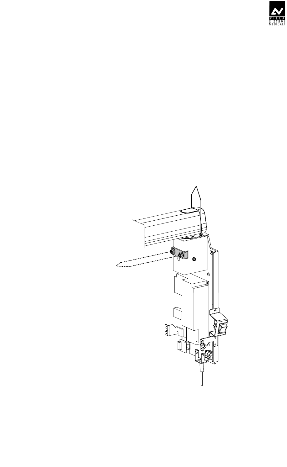
1. Loose the two screws (1 - Figure 6-13) to allow the positioning of the
scissors arm.
2. Assemble the scissors arm (there is no extension arm in this
configuration), being careful to insert the spacer (2 - Figure 6-13)
into the rotation pin. The spacer (code 6161305600) is included in
the mounting hardware packaging.
NOTE:
Be sure that the two pins are inserted into the spacer as showed in the
drawing.
NOTE:
Keep the arm perfectly orthogonal to the pole when inserting the
extension arm rotation pin.
Do not release the scissors arm from their sealing packing.
3. Secure the arm tighten the two screws (1).
2
1
Figure 6-13
SERVICE MANUAL
Installation
(Rev. 2) ENDOGRAPH DC
45
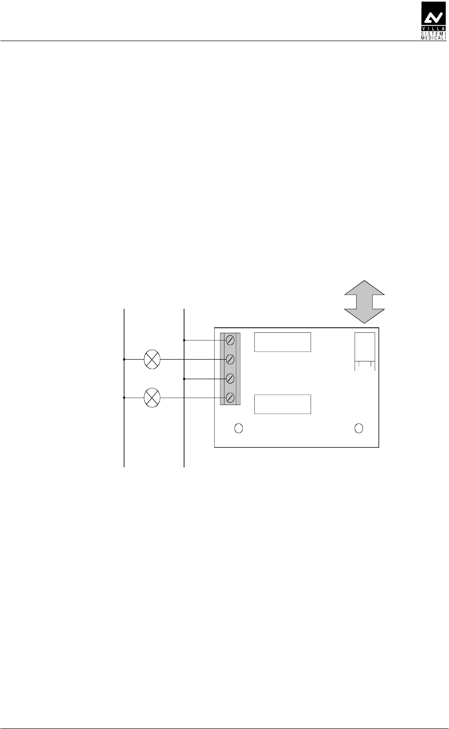
DE
DEDE
DE
DEDFD
DEDFDDEDFD
DEDFD
Endograph DC allows connecting additional signaling devices outside
the room, as specified here below:
• A signaling device indicating "READY" and "RX ON" status can be
connected to X11 connector of the "External signal" board A5
(Figure 6-14).
• To use signaling devices it is necessary to prepare connections using
4 wires having a section of 0.5 mm
2
.
N L
Max 230 Vac
Lamp READY
Lamp RX ON
1
2
3
4
X11
K2
K1
X8
1
CPU
Figure 6-14

SERVICE MANUAL
Installation
ENDOGRAPH DC (Rev. 2)
46
DD
DDDD
DD
E
EE
E
NOTE:
Whatever remote X-ray button installation is implemented, the front
panel of the timer must be visible from the remote button location to
allow the user to see technical factors before starting an exposure.
There are two possible alternative for remote X-ray button:
1. A door bell X-ray button (not provided by Villa Sistemi Medicali) can
be installed following the instruction here below.
NOTE:
The connecting cable between Timer and Remote X-ray button, passing
into the wall or external, must always be put into a metal conduct to
avoid any kind of disturbance to the signals passing through the cable.
The cable can be a maximum of 15 meters long and consequently the
distance between Timer and X-ray button must be shorter than this
length.
The connecting cable must have a 1mm
2
minimum section and must
be connected to the X6.1 and X6.2 connectors on the CPU board A2
(see chapter 12).
The remote X-ray button can be connected in parallel to the
standard X-ray button supplied with the timer, using the same
connectors.
Safety regulations stipulate that a button enabled by an appropriate
safety key must be used.
2. The kit P/N 6659120000 provides a way to install remotely the X-ray
button supplied with the timer.
The kit includes a wall support plate with a terminal strip.
NOTE:
The connecting cable between Timer and remote X-ray button (not
provided by Villa Sistemi Medicali) must have a 1mm
2
minimum section.
The connecting cable must always be put inside a metal conduct to avoid
any disturbance to the signals passing through the cable.

SERVICE MANUAL
Installation
(Rev. 2) ENDOGRAPH DC
47
Remove the X-ray button from the Timer disconnecting the cable
from X6.1 and X6.2 connectors.
Assemble the button on the wall support plate connecting the cable
on the terminal strip.
The connecting cable between Timer and remote X-ray button must
be connected to X6.1 and X6.2 connectors (Timer side) and to the
terminal strip of the support plate.
The support plate has to be fixed on the wall using the fisher type
screws provided.

SERVICE MANUAL
Installation
ENDOGRAPH DC (Rev. 2)
48
EDD
EDDEDD
EDD
E
EE
E
EDDEDED
To insert the battery inside the wireless X-ray button, proceed as follow:
1. unscrew the two screws located on the back of the button
2. open the two half-shells, keeping the green button facing upwards
and paying attention to the electronics located inside
3. insert the batteries respecting the indicated polarities
4. reclose the two half-shells and tighten the screws.
SERVICE MANUAL
Installation
(Rev. 2) ENDOGRAPH DC
49
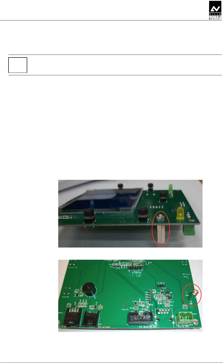
EDDEDD
NOTE:
This procedure has to be performed in case of field upgrade. System
coming with wireless X-ray button are pre-assembled in factory.
The wireless upgrade kit (code 7659303000) includes:
• Wireless X-ray button
• 2 x AAA batteries
• A6 Radio board
• X7 connecting cable.
To assemble the parts proceed as follow:
1. Remove the plastic timer cover (see paragraph 6.1.1 – point 3) and
disconnect the cables between timer and cover.
2. Remove the CPU board from the timer cover.
3. Assemble the hexagonal spacer on the CPU board A2 (component
side) as shown in Figure 6-15 and Figure 6-16.
Figure 6-15
Figure 6-16
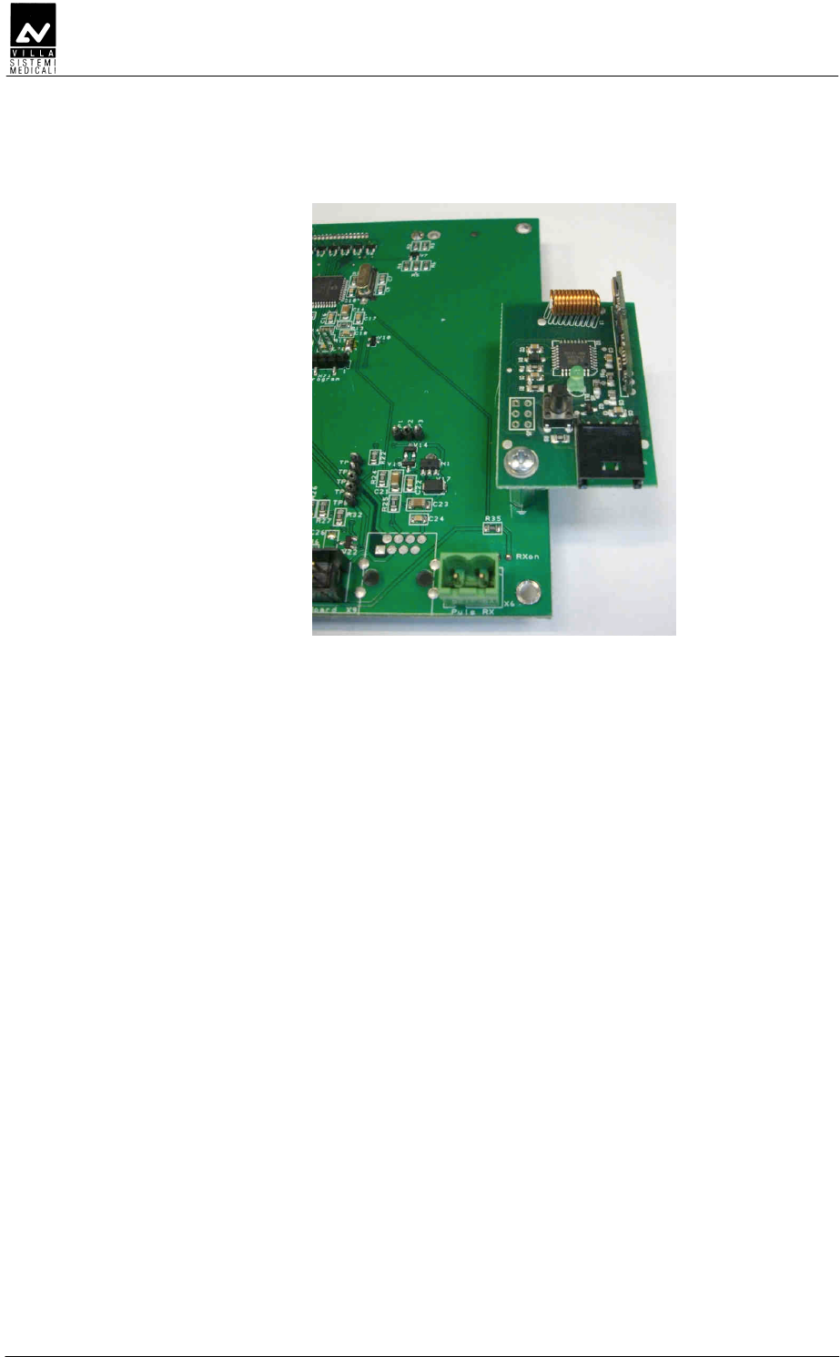
SERVICE MANUAL
Installation
ENDOGRAPH DC (Rev. 2)
50
4. Assemble the A6 Radio board on the CPU board using the provided
screw (Figure 6-17).
Figure 6-17
5. Reassemble the CPU board on the timer cover.
6. Connect the X7 cable between CPU board – connector X7 -
and Radio board – connector J7.
7. Reconnect the cables between timer and CPU board and
reassemble the plastic timer cover.

SERVICE MANUAL
Installation
(Rev. 2) ENDOGRAPH DC
51
EDDEDE
NOTE:
This procedure has to be performed in case of wireless X-ray button
replacement or in case of matching lost.
To match wireless X-ray button and timer, proceed as follow:
1. Switch on the equipment and verify that it is into ready
mode.
2. Press and hold pressed the wireless X-ray button until the
green LED switches on (about 6 seconds).
3. Press and release the wireless X-ray button: the green
LED blinks slowly for three times. If the LED blinks
quickly, the matching failed; repeat the procedure.

SERVICE MANUAL
Installation
ENDOGRAPH DC (Rev. 2)
52
DDDEE
DDDEEDDDEE
DDDEE
NOTE:
The mains power supply has to be provided only on wall support
side.
NOTE:
The connection cable between wall support and remote timer
supplied in the Remote Timer kit (code 6659300100) is 20 meters
long, ending with RJ45 connector.
The maximum distance between wall support and timer must not
exceed the cable length.
ED
For the Remote Timer wall support set-up follow the instruction listed in
paragraph 6.1.1 – Timer set-up (standard configuration).
SERVICE MANUAL
Installation
(Rev. 2) ENDOGRAPH DC
53
DDDED
1 To be sure that the equipment is in the correct position we
recommend you put the provided template code 39599101 (3 -
Figure 6-18) in the requested position, in this way identifying the
requested wall-mounting position. Considering the overall
dimensions of the equipment, put the top part of the template at
1450 mm from the floor.
2 Mark the mounting points and make the relevant holes with the
diameter corresponding to the chosen screws.
3 Remove the plastic timer cover (1 - Figure 6-18) by loosening the two
sealing screws (2 - Figure 6-18) placed on the top part.
4 Fix the timer to the wall using the provided screws (4 - Figure 6-18)
verifying its perpendicularity with the wall accordingly to both axis.
2
3
1
4
4
Figure 6-18

SERVICE MANUAL
Installation
ENDOGRAPH DC (Rev. 2)
54
DED
DEDDED
DED
You are recommend to use chemical screws when installing the
equipment on hollow bricks.
SERVICE MANUAL
Installation
(Rev. 2) ENDOGRAPH DC
55
DED
DEDDED
DED
DEDEE
DEDEEDEDEE
DEDEED
DD
D
FDE
FDEFDE
FDE
NOTE:
Cables coming from the tubehead are supplied for the 80 cm
extension arm.
For the 30 cm and 60 cm extension arm and for mobile stand
version, the surplus part of the cables must be positioned to the top
of the timer with a suitable loop, without passing over the Driver
board area. Fix the cables with the provided strip.
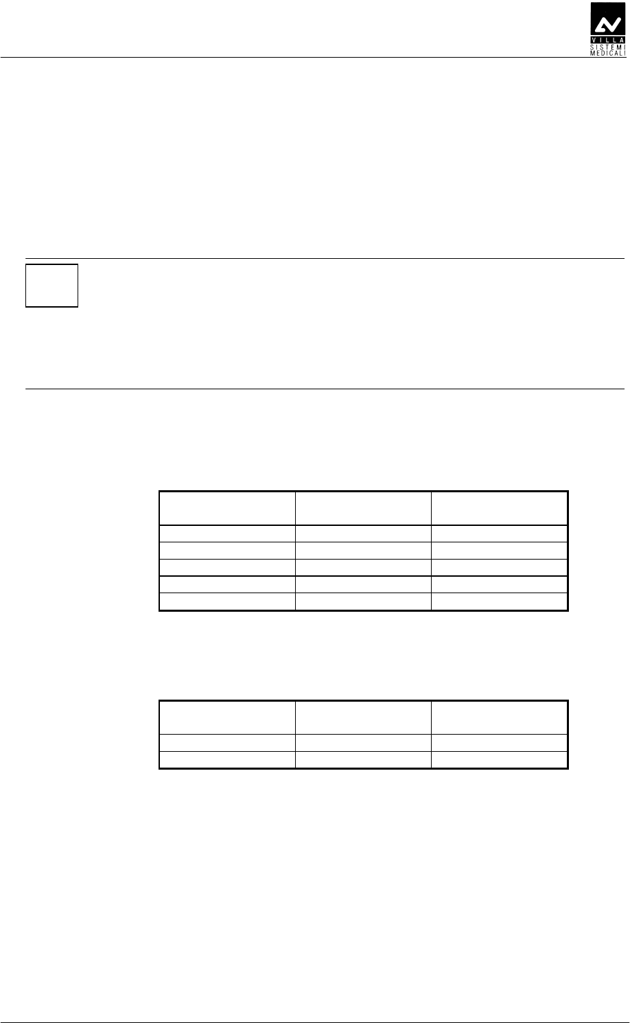
1. Connect the power cables from the tubehead to the Driver board
wiring the cables to the connector X4 (OUTPUT) and shield to screw
W2, following the positions as in the table:
Tubehead wires
colour
Tubehead wires
identification Driver board
Green 1 X4.1
Brown 2 X4.2
White 3 X4.3
Yellow/Green Ground X4.GND
Black Shield Screw W2
2. Connect the signal cable of the tubehead to the Driver board wiring
the cables to the connector X2 (HEATER) following the position as in
the table:
Tubehead wires
colour
Tubehead wires
identification
Driver board
X2 terminal
White/Yellow + +
Green/Brown - -
3. Make the connection between the general switch and the terminal
strip of the timer using a bipolar cable plus ground, section 1.5 mm
2
(16 AWG). Fix the cable to the terminal strip following the positions
as shown (L = line, N = neutral, Ground = yellow/green cable). The
conductors have to be secured to the timer base.
4. Assemble the two pins lock (1 - Figure 6-19) on the timer cover;
these pins (code 2100511300) are included in the mounting
hardware packaging.
SERVICE MANUAL
Installation
ENDOGRAPH DC (Rev. 2)
56
5. Connect the cables between timer and cover: flat cable between CPU
board – connector X1 – and Driver board – connector X1
(CONTROLS); X-ray button cable to CPU board – connector X6.
6. Place the cover on the timer taking care that the cover is positioned
under the upper plate (4 – Figure 6-1). Push the cover against the
locking pins and tighten the two upper screws (2 – Figure 6-1).
X4
W2
X2
Main power supply
terminal strip
1
X1
X5
Figure 6-19
SERVICE MANUAL
Installation
(Rev. 2) ENDOGRAPH DC
57
DEDEDDDE
DEDEDDDEDEDEDDDE
DEDEDDDEFDE
FDEFDE
FDE
ED
1. Remove the X-ray button complete of its support from the timer.
2. Connect the timer following the procedure listed in paragraph 6.5.1,
steps from 1 to 3.
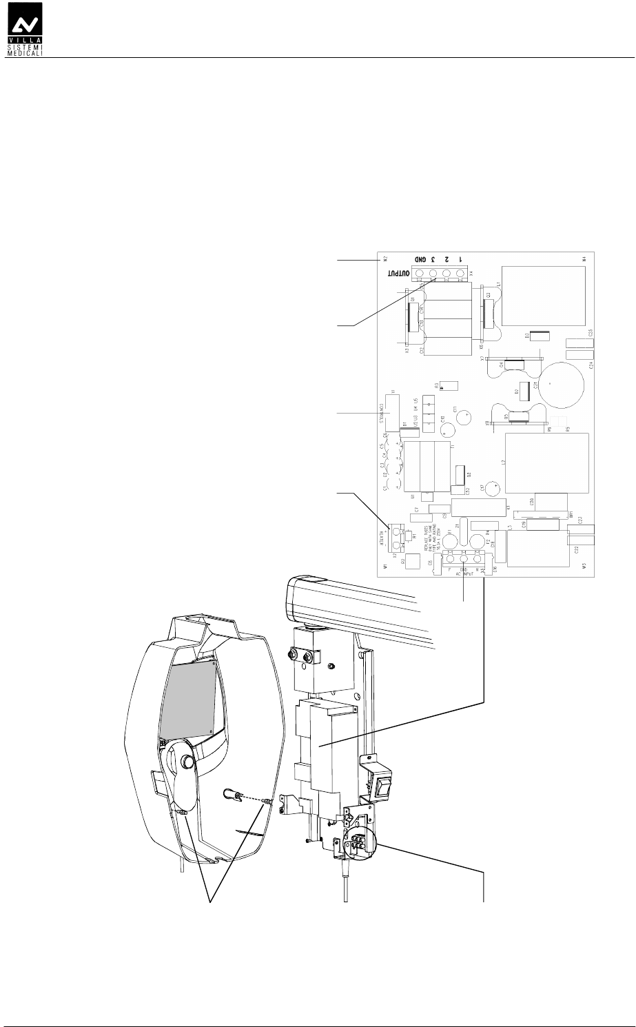
3. Assemble the Remote Interconnection Timer board (A8), included in
the Remote Timer box, on the timer as shown in Figure 6-20.
4. Connect the flat cable, supplied with the Remote Timer box, between
Driver board – connector X1 (Figure 6-19) – and A8 board –
connector X1 (Figure 6-20).
5. Connect the RJ 45 cable to the A8 board – connector X9 (Figure
6-20).
6. Assemble the two pins lock (1 - Figure 6-20) on the Remote Timer
cover (1 - Figure 6-18); these pins (code 2100511300) are included in
the mounting hardware packaging.
7. Place the cover on the timer taking care that the cover is positioned
under the upper plate (4 - Figure 6-1). Push the cover against the
locking pins and tighten the two upper screws (2 - Figure 6-1).
X1
X9
Remote Interconnection
Timer board (A8)
1
Figure 6-20
SERVICE MANUAL
Installation
ENDOGRAPH DC (Rev. 2)
58
DDDED
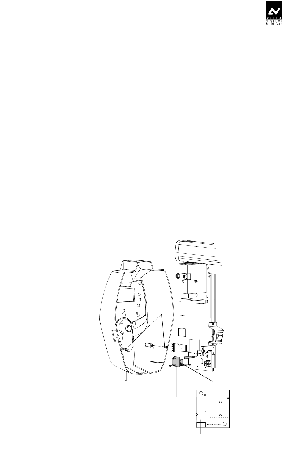
1. Assemble the X-ray button complete of its support (2 - Figure 6-21)
on the Remote Timer plate.
2. Connect the RJ 45 cable to the Remote Interconnection Timer board
(A9) – connector X9 (Figure 6-21).
3. Assemble the two pins lock (1 - Figure 6-21) on the Timer cover (1 -
Figure 6-1); these pins (code 2100511300) are included in the
mounting hardware packaging.
4. Connect the flat cable between CPU board – connector X1 – and A9
board – connector X1. Connect the X-ray button cable to the
connector X6 on the CPU board.
5. Place the cover on the remote support taking care that the cover is
positioned under the upper plate (3 - Figure 6-21). Push the cover
against the locking pins and tighten the two upper screws.
X1
X9
Remote Interconnection
Timer board (A9)
2
3
1
X1 X6
Figure 6-21

SERVICE MANUAL
Installation
(Rev. 2) ENDOGRAPH DC
59
DE
DEDE
DE
DDD
DDDDDD
DDD
At start-up the timer automatically checks all the internal hardware and
particularly:
• Display lights ON
• LEDs light for 2 seconds
• CHECKSUM check of the storage program and display of the words
"CH0" if the check result is negative or in the event of non-initialized
memory
• Buzzer check (rings)
• Check of all buttons and X-ray buttons in particular, no button must
be pressed. If any buttons are pressed an error code message will
appear on the display
• Showing of software and hardware versions (HW: X.XX – SW: X.XX).
NOTE:
During the first start-up, the volatile memory may not be programmed
and therefore the "CH0" message will appear. In this case, press "F" key
to restore the factory default setting. The "CH0" message must not be
displayed any more.
If this happens again, replace the EEPROM on the CPU board and
proceed to the set-up sequence.
WARNING:
Replacing the EEPROM, all the custom tables will be lost.

SERVICE MANUAL
Checks, Calibration and Adjustment
ENDOGRAPH DC (Rev. 1)
60
BABCBC
BABCBCBABCBC
BABCBC
CC
CCCC
CC
The device is calibrated in the factory during final testing carried out at
the manufacturer’s site.
Some adjustments (for example the friction mechanisms of the scissors
arm and extension arm) may need to be done once the installation has
been completed and are described in the installation chapter 6.
ED
EDED
ED
The arms may need adjusting in the following cases:
• the movement of the extension arm combined with the scissors arm
is not considered to be ergonomic by the end user; in this case it will
be necessary to adjust the extension arm frictioning mechanism.
• the scissors arm is not perfectly balanced; in this case you must
adjust the springs.
SERVICE MANUAL
Checks, Calibration and Adjustment
(Rev. 1) ENDOGRAPH DC
61
DDDEEE
DDDEEEDDDEEE
DDDEEE
D
DD
D
The device to adjust the arm support frictioning mechanism is placed on
the front of the wall support. To make this adjustment you have to
proceed as follows.
1. Remove the plastic timer cover by loosening the two sealing screws
(1 - Figure 7-1) placed on the top part of the wall plate.
Be careful to the cables connecting the timer and the plastic cover.
2. Using a 10 mm wrench, adjust the frictioning mechanism nuts (2 -
Figure 7-1) until the movement of the arm is ergonomic.
3. Reposition the plastic cover when you have finished.
2
1
Figure 7-1
SERVICE MANUAL
Checks, Calibration and Adjustment
ENDOGRAPH DC (Rev. 1)
62
DDDEED
DDDEEDDDDEED
DDDEED
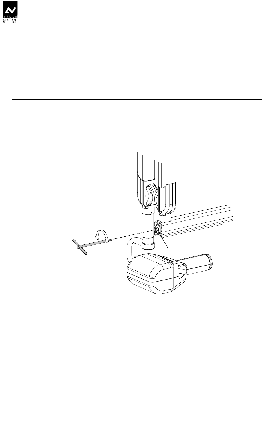
1. Remove the small front extension arm cover, working carefully.
2. Adjust the frictioning mechanism (1 - Figure 7-2) using a 5 mm
hexagon wrench checking the rotation of the scissors arm.
NOTE:
The purpose of this frictioning mechanism is to prevent the scissors from
becoming detached, so it must not be loose.
3. Assemble the cover again.
1
Figure 7-2
SERVICE MANUAL
Checks, Calibration and Adjustment
(Rev. 1) ENDOGRAPH DC
63
DDEE
DDEEDDEE
DDEE
•
••
• DDE
DDEDDE
DDE
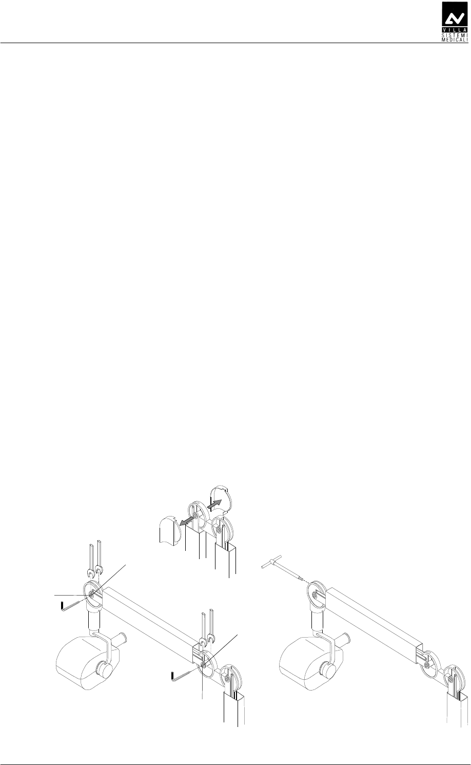
Proceed as follows to adjust the scissors arm:
– Adjusting the friction (for small corrections - picture A)
1. Put the arm in a horizontal position; remove the plastic co-
ordinator covers. This must be done carefully to avoid
breaking the covers themselves.
2. Using a 2.5mm hexagon wrench, loosen the dowel (1).
3. Using two 13 wrenches, adjust the frictioning mechanism by
rotating one of the wrenches ¼ of a turn each time.
4. When you have finished the adjustment, tighten the
previously loosened dowel and reassemble the plastic covers.
– Adjusting the spring (picture B)
If adjustment of the friction is not enough, you can adjust the
spring to optimise the balance:
1 Put the arm in a horizontal position; remove the plastic co-
ordinator covers. This must be done carefully to avoid
breaking the covers themselves.
2 Insert a 6mm hexagon wrench (about 200mm long –
contained in the kit P/N 6661209900). This wrench must
rotate clockwise if the arm tends to go down compared to
the release position; anticlockwise if it tends to go up.
3 When you have finished the adjustment, reposition the
plastic covers.
AB
1
1
2
2
Ø13
Ø13
Figure 7-3
SERVICE MANUAL
Checks, Calibration and Adjustment
ENDOGRAPH DC (Rev. 1)
64
•
••
• DEE
DEEDEE
DEE
If the first arm also needs to be adjusted:
– Adjusting the friction (for small corrections - picture A)
1 Close the arm scissors arm; remove the plastic co-ordinator
covers. This must be done carefully to avoid breaking the
covers themselves.
2 Using a 2.5mm hexagon wrench, loosen the dowel (1).
3 Using two 13 wrenches, adjust the frictioning mechanism by
rotating one of the wrenches ¼ of a turn each time.
4 When you have finished the adjustment, tighten the
previously loosened dowel and reassemble the plastic covers
– Adjusting the spring (picture B)
If adjustment of the friction is not enough, you can adjust the
spring to optimise the balance:
1. Put the arm in a horizontal position; remove the plastic co-
ordinator covers. This must be done carefully to avoid
breaking the covers themselves.
2. Insert a 6mm hexagon wrench (about 200mm long –
contained in the kit P/N 6661209900). This wrench must
rotate clockwise if the arm tends to go down compared to
the release position; anticlockwise if it tends to go up.
3. When you have finished the adjustment, reposition the
plastic covers
Ø13
AB
2
1
2
1
Figure 7-4
SERVICE MANUAL
Set-up
(Rev. 1) ENDOGRAPH DC
65
C
CC
C
The Endograph DC system has a modifiable configuration that can be
adapted to specific usage needs.
To enter the "set-up" function press the "Increase" and
"Decrease" keys simultaneously during the software / hardware
version display phase; the display will show:
DEEFABAACCDE
ABAF
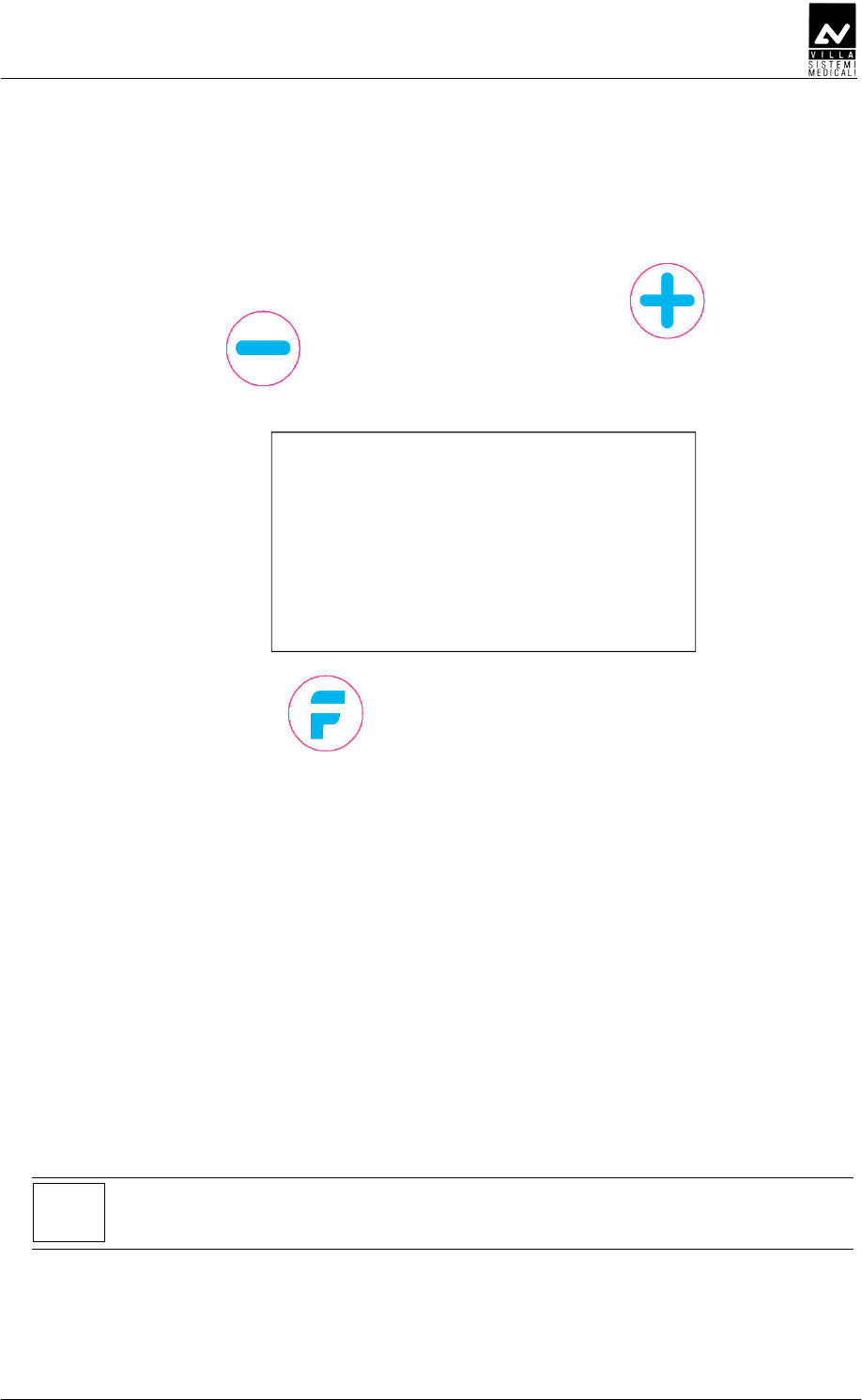
Press "Function" key to go to the following parameter; touch
either the "Increase" or "Decrease" keys to change the displayed
parameter value.
Press "Function" key and then confirm (Increase key) or cancel (decrease
key) the new setting.
Press and hold pressed the "Function" key to exit the setup program, the
system will restart.
P00:
C
CC
C
D
DD
D
This parameter indicates the time in minutes after that the system enter
in "sleep" condition.
With "Value = 0", the system is always in the "Ready for X-rays"
conditions. The selectable value changes between 0 and 5 (default 2).
NOTE:
When Value = 0, the green "Ready for X-rays" LED is always ON.
SERVICE MANUAL
Set-up
ENDOGRAPH DC (Rev. 1)
66
P01:
D
DD
D
This is the value of parameter K (value selectable between 0 and 80)
which, multiplied by the current value of exposure time, calculates the
value of the cool down time between consecutive exposures.
COOL DOWN BETWEEN EXPOSURES = Exposure time x K
Default value = 60 (sixty times the exposure time).
WARNING:
This parameter must not be changed from the factory configuration.
Changing on this parameter may effect on the equipment life time.
P02:
EDBDE
EDBDEEDBDE
EDBDE
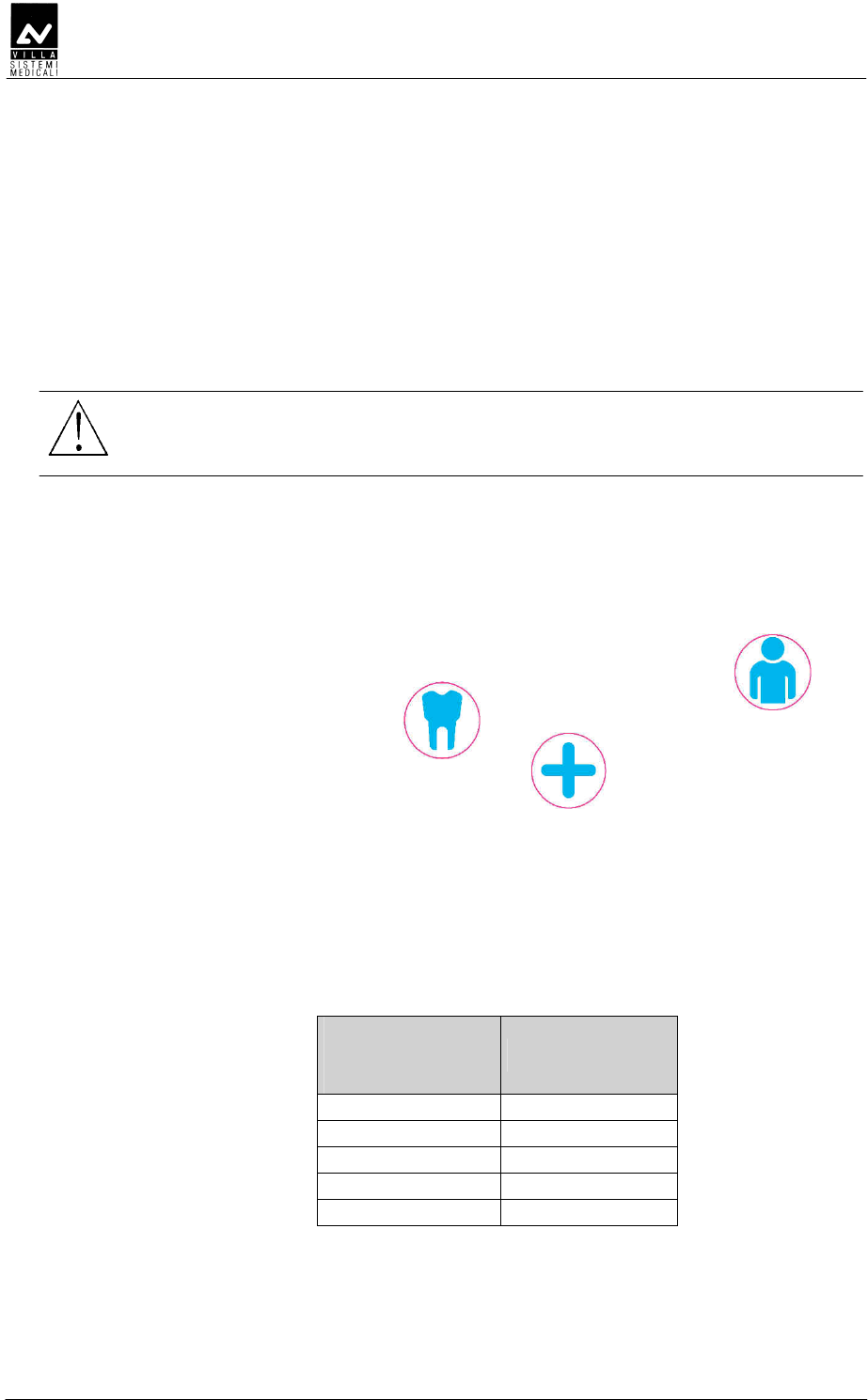
This parameter shows the number of the performed exposure. The
counter can be reset to zero by pressing the "Size Selection" and
"Tooth automatic selection" keys together; the operation requires
confirmation, by pressing the "Increase" key.
P03:
DF
DFDF
DF
This parameter adapts the exposure times associated to Anatomic and
Size selections to the film speed used by the user.
The available values are shown in the following table:
Value
(multiplies the
pre-set exp. time)
Film type
0.75 --
1.00 F
1.25 E
1.50 --
2.00 D
Default value = 1.00 (F)
SERVICE MANUAL
Set-up
(Rev. 1) ENDOGRAPH DC
67
P04:
D
DD
D
When you use a 30 cm limiter cone, the exposure times in the preset
tables must be multiplied by a 2 factor to get a correct dose.
The default value is "OFF", which corresponds to the standard cone (Film
Focus Distance = 20cm).
The change from standard cone to long cone times is made by selecting
"ON".
This setting is available also in normal working or out of set-up program
modes, and it is available to the user.
P05:
This parameter makes it possible to vary the display back light, in order
to compensate any differences in environmental light. Values are
changed by "Increase" and "Decrease" keys.
P06:
DBEEDE
DBEEDEDBEEDE
DBEEDE
This parameter is used only during factory test.
NOTE:
Do not modify factory configuration.
P07:
D
DD
D
Using "Increase" and "Decrease" keys, select the desired language
between: English, Italian, French, Spanish, German, Portuguese,
Russian, Dutch, Arabic, Turkish, Chinese (traditional), Chinese
(simplified), Symbols only (visualize only the tooth symbol).
SERVICE MANUAL
Set-up
ENDOGRAPH DC (Rev. 1)
68
P08:
EDE
EDEEDE
EDE
This parameter allows to visualize / hide Villa logo at system start-up.
Default value = Show Logo.
P09:
D
DD
D
DD
DDDD
DD
This parameter make it possible to enable / disable the X-Rays emission.
Default value = X-Rays ENABLED (ON).
P10:
DEDFDED
DEDFDEDDEDFDED
DEDFDED
This parameter allows to change the display between white text on blue
background and blue text on white background.
Default value = OFF (white text on blue background).
P11:
BBED
BBEDBBED
BBED
This parameter makes it possible to vary the contrast of the display, in
order to compensate any differences in environmental light.
Two adjustments are possible:
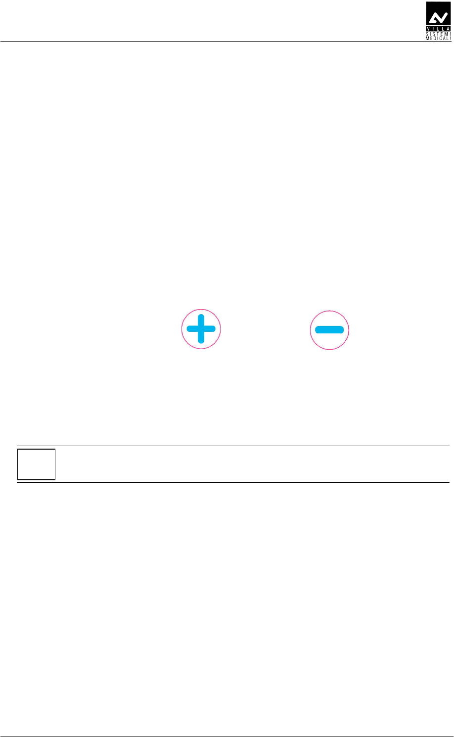
− Press " Tooth automatic selection" key for a coarse
regulation. Default value = 2
− Press "Increase" and "Decrease" keys for a fine
regulation. Default value = 24.

SERVICE MANUAL
Set-up
(Rev. 1) ENDOGRAPH DC
69
P12:
DDDED
DDDEDDDDED
DDDED
This parameter makes it possible to enable / disable the acoustic sound
on key press.
Default value = ON
P13:
EDDED
EDDEDEDDED
EDDED
This parameter is used only during factory test.
NOTE:
Do not modify factory configuration.
P14:
DEDECD
DEDECDDEDECD
DEDECD
Select value = ON to restore the system configuration and the custom
time tables to factory default.
After confirmation, the system will restart with factory settings.
NOTE:
All custom settings will be lost.
SERVICE MANUAL
Set-up
ENDOGRAPH DC (Rev. 1)
70
DDDFDEED
DDDFDEEDDDDFDEED
DDDFDEED
EDDE
EDDEEDDE
EDDE
Display
Parameters Set Value New setting WARNING
P00
Stand-by timeout 2 min
P01
Duty cycle 60 (1)
P02
Exposure Counter ////
P03
Film sensitivity 1.00
P04
Long cone OFF
P05
Display back light ////
P06
Dose Correction Factor ////
P07
Language ////
P08
Manufacturer's Logo Show logo
P09
Disable X-Rays X-ray enabled
(ON)
P10
Display mode reverse OFF
P11
LCD Contrast Adjustment ////
P12
Beep on keypress ON
P13
Exposure extra time 0 (1)
P14
Restore Factory Settings ////
WARNING:
Parameters shown with (1) in the previous table can not be changed; the
perfect running of the system or its compliance with Directive CE 93/42
cannot be guaranteed if any change is made.
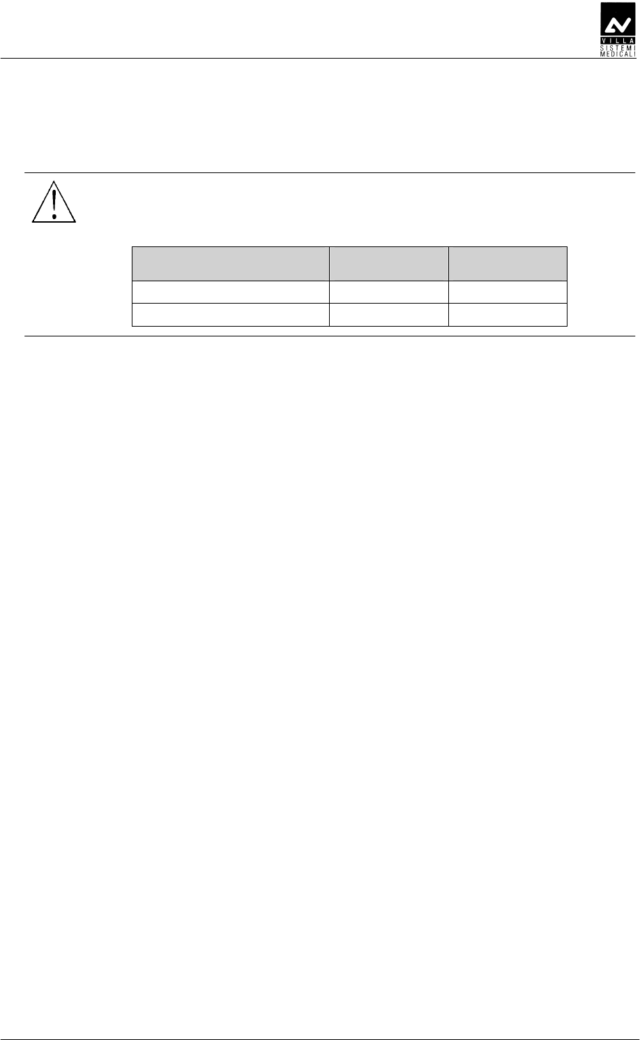
SERVICE MANUAL
Troubleshooting
(Rev. 1) ENDOGRAPH DC
71
CA
CACA
CA
WARNING:
The system must be switched off before performing integrity checks
on fuses and components.
System F1 F3
110 – 240 V wall version 6.3 AT 250 V -
110 – 240 V stand version 6.3 AT 250 V 6.3 AT 250 V
• Symptom:
Display off when main switch is ON
• Action:
− check if the LED on the keyboard are ON and pressing the
keyboard buttons you can hear any beep.
If the keyboard doesn't work, switch OFF the equipment and verify:
− the flat cable connecting the CPU and the Driver board
− integrity of fuses F1 and F3 (if present)
− measure the presence of the main power supply.
If no anomalies are found, start replacing boards in the following
order: CPU, Driver board (including tubehead).

SERVICE MANUAL
Troubleshooting
ENDOGRAPH DC (Rev. 1)
72
EEEDDD
EEEDDDEEEDDD
EEEDDD
As described in chapter 3, the Endograph DC is totally controlled by a
microprocessor which, not only checks the programming of exposure
parameters but also signals the various machine statuses and any
anomalies and errors, by messages in code on the display unit.
The following tables contain the various messages which may appear on
the display, their meanings, their cause and how to behave.
NOTE:
Error messages belong to three different groups, classified according to
the seriousness of the anomalies found and their possible effect on the
safety of the operators’ and/or the system.
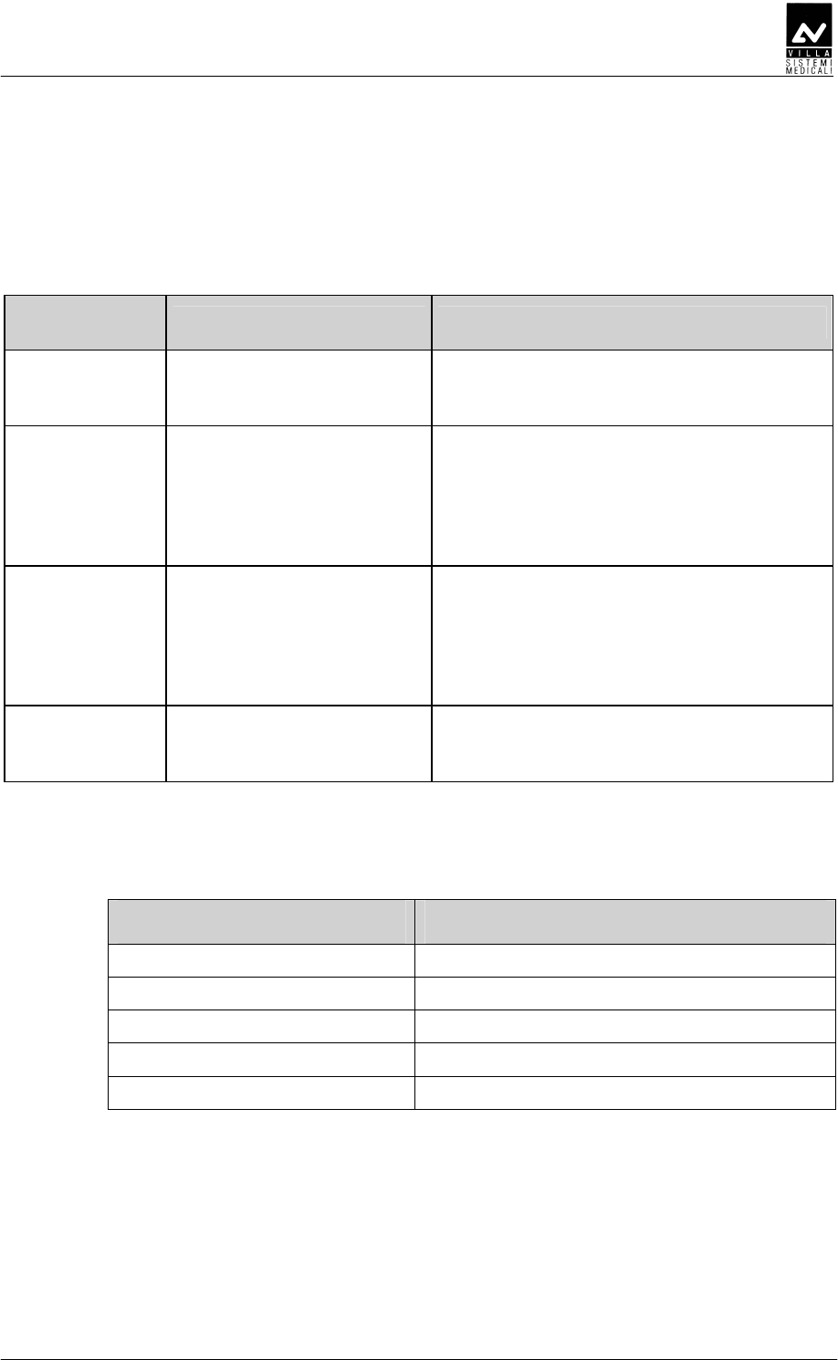
SERVICE MANUAL
Troubleshooting
(Rev. 1) ENDOGRAPH DC
73
DEEEDE
DEEEDEDEEEDE
DEEEDE
DEDD
DEDDDEDD
DEDD
D
DD
D
These signals DO NOT allow any examination to be performed.
Displayed
message ANOMALY type Corrective actions
E01
X-ray button pressed at
start-up
Switch the system off and on again; if the
message is still present, replace the X-ray
button.
E02
A key pressed at start-up
(different from X-ray button)
The pressed button is identified by an
hexadecimal code according to Table 1
Verify that the relevant button is not really
pressed. Switch the system off and on
again; if the message is still present,
replace the CPU board.
E03
More keys pressed at start-
up
The pressed button is identified by an
hexadecimal code according to
Verify that the relevant button is not really
pressed. Switch the system off and on
again; if the message is still present,
replace the CPU board.
E05
Unwanted X-ray emission Switch the system off and on again; if the
message is still present, replace the
tubehead and the Driver board.
The main key codes used to identify the pressed button are listed in the
following table:
Code Description
0001 Function key (F)
0002 Increment key (+)
0004 Tooth key
0008 Decrement (-) key
0010 Size key
Table 1
All other key codes identify a combination of two or more pressed
buttons.
SERVICE MANUAL
Troubleshooting
ENDOGRAPH DC (Rev. 1)
74
DEEE
DEEEDEEE
DEEEE
EE
E
ED
EDED
ED
Possible anomalies during exposure always interrupt the exposure itself.
Whether there is an acoustic signal or not depends on the time the fault
occurred and on the success of the X-ray interruption procedure.
Displayed
message ANOMALY type Corrective actions
E04
No emission (breakage in
the filament circuit)
Measure the impedance value between "+"
and "-" of Driver board - connector X2
(HEATER); this value must be lower than
20 ohm.
If the value is greater than 20 ohm, remove
the tubehead plastic covers and measure
the impedance value between J3.IN+ and
J3.IN- of Filament Voltage Regulator board.
If the value is still greater than 20 ohm,
disconnect the cables J3.Fil+ and J3.Fil-
from the Filament terminal strip and
measure the impedance value between
them.
If the measured value is lower than
20 ohm, replace the DP arm, otherwise
replace tubehead and Driver board.
E06
Activation of the back-up
timer
Check integrity of the flat cable connecting
the CPU to the Driver board.
Switch the system off and on again; if the
message is repeated after an exposure,
replace the Driver board and the tubehead.
E07
Protection intervention Switch the system off and on again; if the
message is still present, replace the Driver
board and the tubehead.
WARNING:
When an error signal appears and the buzzer sounds, always switch
the system off. In any case when the back-up timer is triggered it
always interrupts X-ray emission.
SERVICE MANUAL
Troubleshooting
(Rev. 1) ENDOGRAPH DC
75
DEEE
DEEEDEEE
DEEE
Situations which do not directly effect the safety of the operator, patient
or the system are considered as re-settable anomalies.
The error condition prevents additional exposures until it is reset
by pressing the "Increase" key.
Displayed
message ANOMALY type Corrective actions
CH0
Memory checksum error
(EEPROM)
If present at the first start-up of the
equipment after replacing EEPROM, follow
the displayed procedure.
On the contrary, if present during normal
working, replace the EEPROM, if not
enough, replace CPU board.
E11
X-ray button active after
the cooling phase
Release the X-ray button and follow the
displayed procedure.
If the X-ray button is not pressed, switch
off the system and replace the button.
E12
Release of X-ray button
during emission
Reset the error and repeat exposure.
Make sure NOT to release the X-ray button
before the buzzer stops.
If the message is still present, replace the
X-ray button.
E13
Release of X-ray button
during pre-heating phase
Reset the error and repeat exposure.
Make sure NOT to release the X-ray button
before the buzzer stops.
If the message is still present, replace the
X-ray button.
SERVICE MANUAL
Replacing parts
ENDOGRAPH DC (Rev. 1)
76
BC
BCBC
BC
NOTE:
The Service Engineer has to take special care for all what concerns
electrical safety of the device and must make sure of restoring all
provisions for electrical safety which may be affected during a service
intervention and to solicit the customer to have the electrical safety tests
repeated every time the intervention has caused the replacement of
important parts or the intervention has significantly affected safety
provisions of the device.
DDDD
DDDDDDDD
DDDDDEFDEE
DEFDEEDEFDEE
DEFDEE
WARNING:
The tubehead and the Diver board are matched in the factory and
therefore MUST be replaced as a couple.
WARNING:
Before proceeding with the replacement of the tubehead, close and tie
the two sections of the scissors arm together.
Failure to follow these instruction may harm both the technician and
damage the arm itself.
NOTE:
Before carrying out the following operations, disconnect the equipment
from the line.
NOTE:
No specific actions are required after replacing the tubehead and the
Driver board.

SERVICE MANUAL
Replacing parts
(Rev. 1) ENDOGRAPH DC
77
DDDD
DDDDDDDD
DDDD
NOTE:
The spare tubehead is always shipped with a new set of plastic covers
and with a new identification plate, giving the new serial numbers of the
tubehead itself and of RX tube.
1. Remove the tubehead covers removing the front fixing ring of the
extension cone and loosing the two screws (one on each part) located
under the lateral triangular labels; gently open the two plastic
covers.
2. Disconnect the cables coming from the scissor arm.
3. Holding the tubehead, unscrew the extension cone and remove the
four fixing screws fixing the tubehead itself to the support. Remove
the tubehead.
4. Take the new tubehead and assemble it on the support.
5. Connect the cables coming from the arm with the corresponding
connectors on the tubehead.
6. Assemble the new plastic covers set.
DDEFDEE
DDEFDEEDDEFDEE
DDEFDEE
1.
Remove the plastic timer cover loosening the two sealing screws
placed on the top part. Pull the cover to release the locking pins.
To make the operation easier, disconnect all wires between wall plate
and cover. The flat cable connecting the CPU board and the Driver
board has to be removed from the connector on the Driver board.
2.
Disconnect cables from connectors X2, X4 (including shield W2) and
main power supply cable from connector X5 (Figure 6-19).
3.
Remove the board and assemble the new one, fixing it.
4.
Connect the cables disconnected at step 2.
5.
Connect all the connections cables between wall plate and cover;
close the timer again.

SERVICE MANUAL
Replacing parts
ENDOGRAPH DC (Rev. 1)
78
D
DD
D
DB
DBDB
DBE
EE
E
NOTE:
Before carrying out the following operations, disconnect the equipment
from the line.
1.
Remove the plastic timer cover loosening the two sealing screws
placed on the top part. Pull the cover to release the locking pins.
To make the operation easier, disconnect all wires between wall plate
and cover. The flat cable connecting the CPU board and the Driver
board has to be removed from the connector on the CPU board.
2.
Remove the failed CPU board and replace it with the new one.
NOTE:
If the system is equipped with the wireless X-ray button, remove from
the failed CPU board the A6 Radio board (Figure 6-17) complete of cable
X7 and exagonal spacer support and assemble it on the new CPU board
as described in paragraph 6.4.3.2, steps 3 and following.
3.
Connect all the connections cables between wall plate and cover;
close the timer again.
4.
Switch the system on and enter the setup procedure (chapter 8).
Check all configuration parameters.
NOTE:
It is possible to save the stored customized table, removing the EEPROM
from the old CPU to the new one.

SERVICE MANUAL
Replacing parts
(Rev. 1) ENDOGRAPH DC
79
DDD
DDDDDD
DDD
Replacing the keypad consists in replacing the adhesive membrane:
remove the timer covering panel, remove the old membrane carefully and
clean the surface where the membrane was attached.
NOTE:
Do not use solvent, but only alcohol.
Attach the new membrane.
SERVICE MANUAL
Replacing parts
ENDOGRAPH DC (Rev. 1)
80
DDEE
DDEEDDEE
DDEE
DDEEDEE
DDEEDEEDDEEDEE
DDEEDEE
E
EE
E
WARNING:
Before to remove the tubehead, close and tie the two sections of the
scissors arm together.
Failure to follow these instruction may harm both the technician and
damage the arm itself.
NOTE:
Before carrying out the following operations, disconnect the equipment
from the line.
1.
Remove the tubehead as described in paragraph 10.1.1, steps from 1
to 3.
2.
Remove the plastic timer cover loosening the two sealing screws
placed on the top part. Pull the cover to release the locking pins.
To make the operation easier, disconnect all wires between wall plate
and cover.
3.
Remove the front covers of the extension arm.
4.
Disconnect cables from connectors X2 and X4 (including shield W2)
(Figure 6-19). Remove the cables from the extension arm completely.
5.
Remove the friction group on the extension arm as described in
paragraph 6.3.2, steps 1 and 2; remove the arm.
6.
Assemble the new arm as described in paragraph 6.3.2, steps 3 and
following.
7.
Connect the cables ad described in paragraph 6.5.1.
8.
Reassemble the tubehead as described in paragraph 10.1.1, steps
from 4 to 6.

SERVICE MANUAL
Replacing parts
(Rev. 1) ENDOGRAPH DC
81
DDEED
DDEEDDDEED
DDEED
WARNING:
Before to remove the tubehead, close and tie the two sections of the
scissors arm together.
Failure to follow these instruction may harm both the technician and
damage the arm itself.
NOTE:
Before carrying out the following operations, disconnect the equipment
from the line.
1.
Remove the tubehead as described in paragraph 10.1.1, steps from 1
to 3.
2.
Remove the plastic timer cover loosening the two sealing screws
placed on the top part. Pull the cover to release the locking pins.
To make the operation easier, disconnect all wires between wall plate
and cover.
3.
Disconnect cables from connectors X2 and X4 (including shield W2).
Disconnect the main power supply cable from the main power supply
terminal strip (Figure 6-19).
4.
Remove the timer from the support plate.
5.
Remove the scissor arm.
6.
Assemble the new arm as described in paragraph 6.3.3.
7.
Fix the support plate and the timer as described in paragraph 6.2,
steps 5 and following.
8.
Connect the cables as described in paragraph 6.5.1.
9.
Reassemble the tubehead as described in paragraph 10.1.1, steps
from 4 to 6.

SERVICE MANUAL
Maintenance
ENDOGRAPH DC (Rev. 1)
82
B
BB
B
Like all electrical equipment, this unit requires not only correct use, but
also maintenance and checks at regular intervals. This precaution will
guarantee that the equipment works safely and efficiently.
Periodic maintenance consists in checks carried out directly by the
operator and/or by the Technical Service.
The operator can carry out the following checks himself:
• check there are no oil marks on the tubehead
• check the remote control cable is not broken or scratched
• check there are no external damages to the equipment which could
make it unsafe in terms of protection from radiation
• check the scissors arm balance
• check that the X-ray beam is centered
• check proper functioning of X-ray exposure LED and exposure
buzzer
• check the plates are intact and well attached.
The Service Engineer, during preventive maintenance, besides the
checks listed above, will verify also:
• correct adjustment of the rotation friction mechanism of the
extension arm and of the scissors arm
• correct balancing of scissors arm, making proper adjustment when
necessary.
NOTE:
The Service Engineer has to take special care for all what concerns
electrical safety of the device and must make sure of restoring all
provisions for electrical safety which may be affected during a service
intervention and to solicit the customer to have the electrical safety tests
repeated every time the intervention has caused the replacement of
important parts or the intervention has significantly affected safety
provisions of the device.
NOTE:
Interventions carried out by the Service Engineer must be noted in the
Maintenance Record page at the end of the User Manual, with a short
description of the actions done

SERVICE MANUAL
Schematics and drawings
(Rev. 1) ENDOGRAPH DC
83
CBABC
CBABCCBABC
CBABCC
CC
C
1. ENDOGRAPH DC – General connection diagram

SERVICE MANUAL
Schematics and drawings
ENDOGRAPH DC (Rev. 1)
84
THIS PAGE IS INTENTIONALLY LEFT BLANK
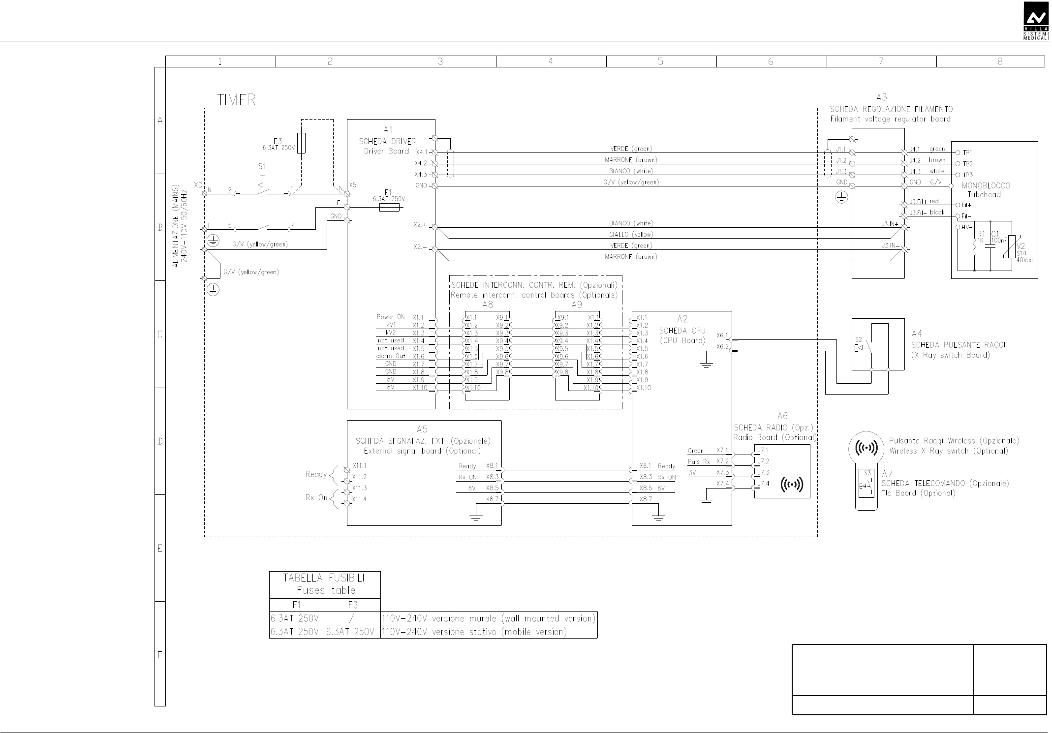
SERVICE MANUAL
Schematics and drawings
(Rev. 1) ENDOGRAPH DC
85
AB
DDED
E
BDDF
D

SERVICE MANUAL
Schematics and drawings
ENDOGRAPH DC (Rev. 1)
86
THIS PAGE IS INTENTIONALLY LEFT BLANK

SERVICE MANUAL
Spare Parts
(Rev. 1) ENDOGRAPH DC
87
CC
CCCC
CC
AB
ABAB
AB
CCBCC
CCBCCCCBCC
CCBCC
C
CC
C
A
AA
A

SERVICE MANUAL
Spare parts
ENDOGRAPH DC (Rev. 1)
88
AB
ABAB
AB
WARNING:
The Driver board and the tubehead are matched in the factory and
therefore MUST be replaced as a couple.
D
DD
D
CD
CDCD
CD
DE
DEDE
DE
D
DD
D
1 6159300100 Frictioning mechanism assy
2 6659400000 A2 Driver board and Tubehead
assembly
5859301000 A2 CPU board 3
4695463800 A6 Radio board Present only
with wireless
X-ray button
-- 6259300300 Flat cable CPU-Driver board
4 4291420900 ON/OFF switch
6659300500 X-ray push button 5
6659300600 Wireless X-ray push button
6 5459301200 Timer keypad
7 6659300200 Timer front cover complete of
keypad
8 5459301600 Remote timer keypad
9 6659300400 Remote timer front cover complete
of keypad
10 5859301400 A8 / A9 Remote Interconnection
control board
Present only
with Remote
Timer version
11 5859301200 A5 External signal board Optional
F1 2300997200 Fuse 6.3 A T 6.3x32 250V Mounted on
Power PCB
F3 2300997200 Fuse 6.3 A T 6.3x32 250V For mobile
version
4560311800 Fuse holder -
4560311900 Cap for fuse holder
For mobile
version
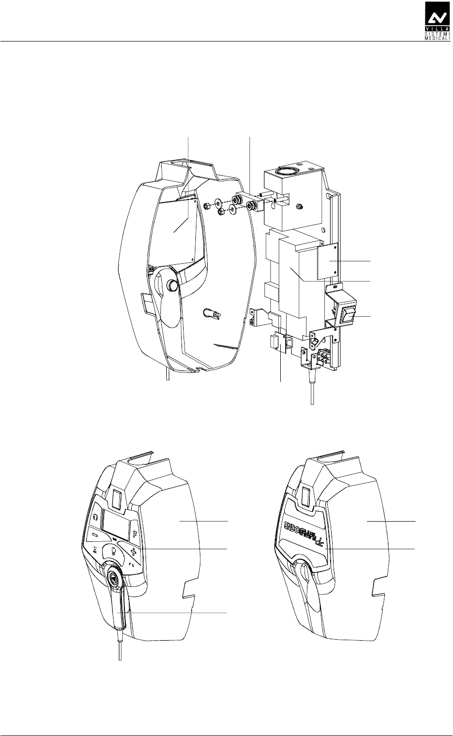
SERVICE MANUAL
Spare Parts
(Rev. 1) ENDOGRAPH DC
89
7
6
5
8
9
3 1
2
4
10
11

SERVICE MANUAL
Spare parts
ENDOGRAPH DC (Rev. 1)
90
CCBCC
CCBCCCCBCC
CCBCC
D
DD
D
CD
CDCD
CD
DE
DEDE
DE
D
DD
D
1 8159200000 Scissor arm complete of
tubehead support
8161200302 Extension arm 30 cm
8161200502 Extension arm 60 cm
2
8161200402 Extension arm 80 cm
3 6661210013 Scissor arm joint covers kit
(DX + SX)
4 6659210013 Extension arm end-covers kit
5 6659210100 Extension arm frictioning
mechanism
6 5160249500 Busher
∅
28 mm
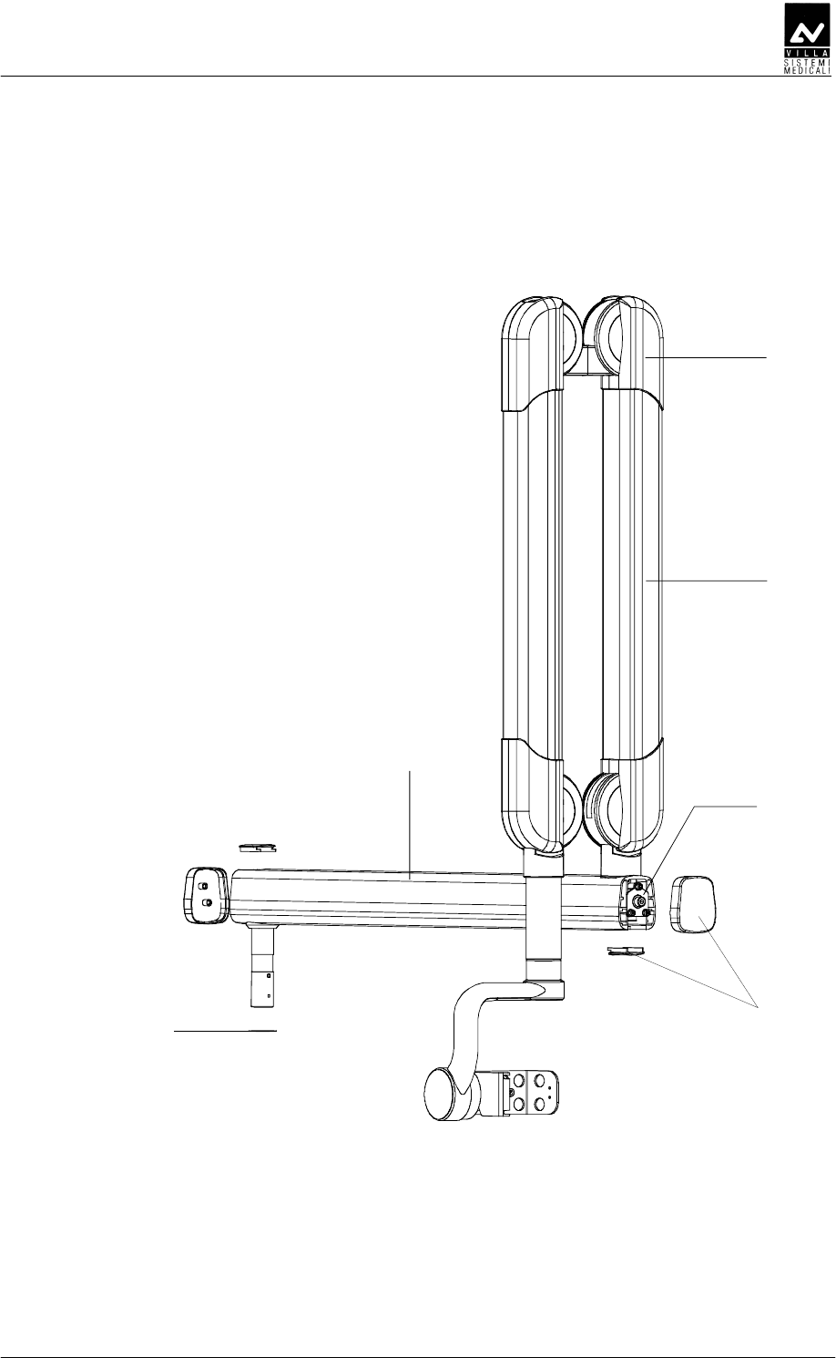
SERVICE MANUAL
Spare Parts
(Rev. 1) ENDOGRAPH DC
91
1
2
3
64
5

SERVICE MANUAL
Spare parts
ENDOGRAPH DC (Rev. 1)
92
C
CC
C
D
DD
D
CD
CDCD
CD
DE
DEDE
DE
D
DD
D
1 8160120000 Mobile stand complete
4890310400 Wheel with brake 80x24 2
4890307000 Wheel 80x24
3 6661305600 Mobile stand spacer
4 5259300105 Timer fixing plate
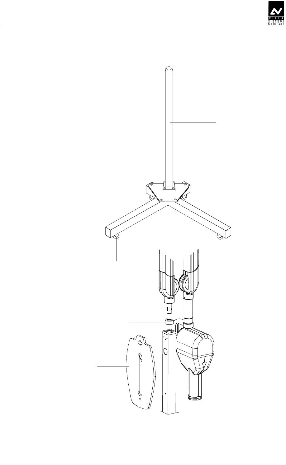
SERVICE MANUAL
Spare Parts
(Rev. 1) ENDOGRAPH DC
93
1
2
3
4

SERVICE MANUAL
Spare parts
ENDOGRAPH DC (Rev. 1)
94
A
AA
A
WARNING:
The tubehead and the Diver board are matched in the factory and
therefore MUST be replaced as a couple.
D
DD
D
CD
CDCD
CD
DE
DEDE
DE
D
DD
D
1 6659400105 Tubehead covers kit (without plate)
2 5460461813 Front fixing ring
3 5160423813 Angle indicator
4 5460420813 Tubehead lateral cover
5 6659400000 Tubehead complete assembly
including Driver board
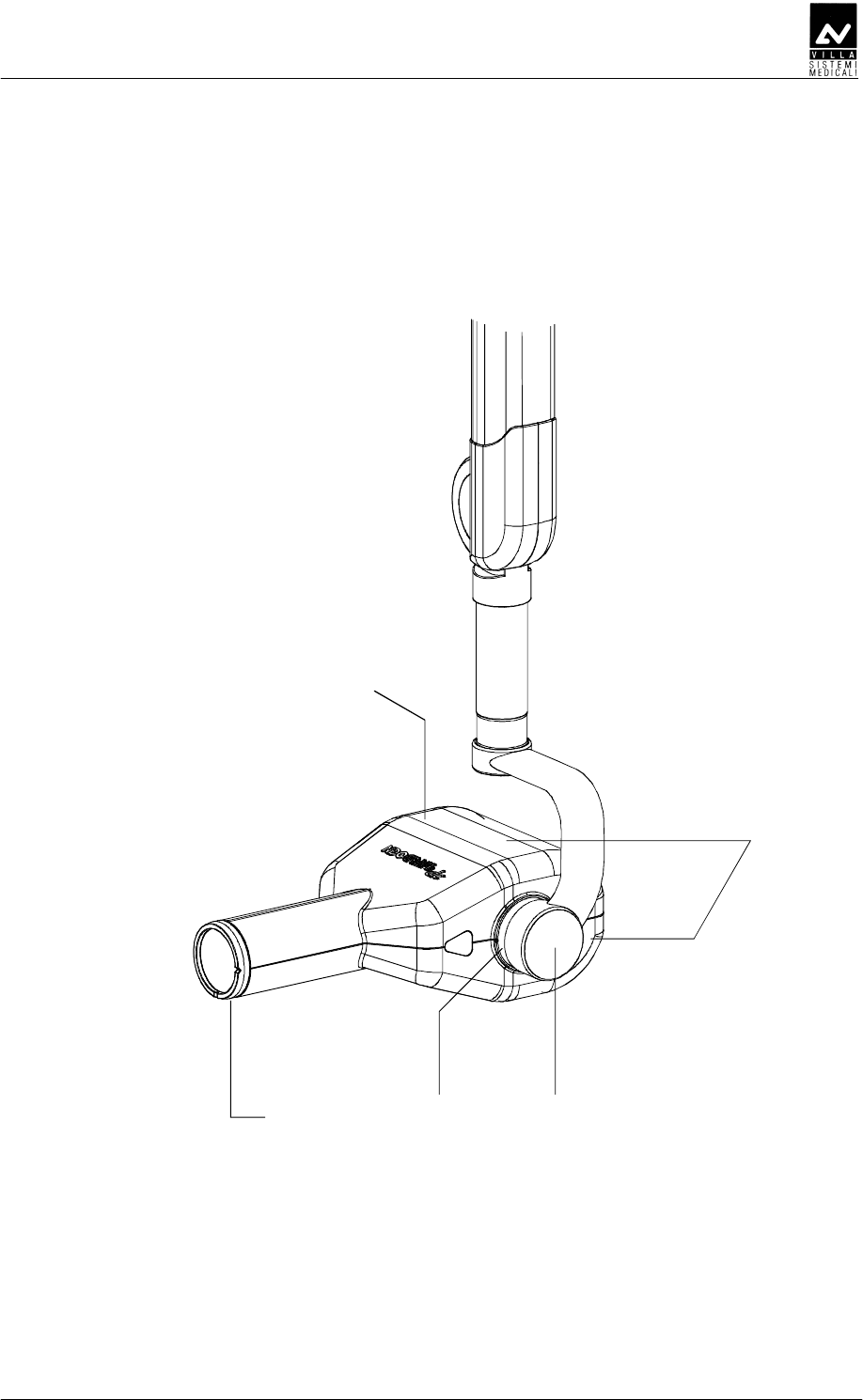
SERVICE MANUAL
Spare Parts
(Rev. 1) ENDOGRAPH DC
95
2 3
5
4
1

SERVICE MANUAL
Spare parts
ENDOGRAPH DC (Rev. 1)
96
D
DD
D
CD
CDCD
CD
DE
DEDE
DE
D
DD
D
1 6659300100 Remote Timer kit
2 6659120000 Remote X-ray button support
3 7659303000 Wireless upgrade kit for wired X-ray
button.
4 7659303100 External lamp connection kit
5 6159400000 Extension cone for 30cm Source to
Image Distance
6 6159410000 Rectangular beam limiting device
45x35mm
7 6159410100 Rectangular beam limiting device
25x35mm
8 6159410200 Rectangular beam limiting device
20x30mm
9 6659200100 Allen wrenches kit

SERVICE MANUAL
Spare Parts
(Rev. 1) ENDOGRAPH DC
97
THIS PAGE IS INTENTIONALLY LEFT BLANK

SERVICE MANUAL
Spare parts
ENDOGRAPH DC (Rev. 1)
98
THIS PAGE IS INTENTIONALLY LEFT BLANK

SERVICE MANUAL
Fixing templates
(Rev. 1) ENDOGRAPH DC
99
C
CC
C
The system is equipped with a set of templates, composed of the
following elements:
Code Description
39599100 Template for standard version
39599101 Template for remote version

SERVICE MANUAL
Fixing templates
ENDOGRAPH DC (Rev. 1)
100
THIS PAGE IS INTENTIONALLY LEFT BLANK

Cod. 6959900703_Rev.1
0051
VILLA SISTEMI MEDICALI S.p.A.
Via Delle Azalee, 3
20090 Buccinasco (MI) – ITALY
Tel. (+39) 02 48859.1
Fax (+39) 02 4881844