Vision Automobile Electronics Co ZA1002US-5 Z-Wave Smart Gateway User Manual
Vision Automobile Electronics Industrial Co Ltd Z-Wave Smart Gateway Users Manual
UserManual.wiki
>
Vision Automobile Electronics Co
>
ZA1002US-5 User Manual
>
Users Manual
Contents
1.
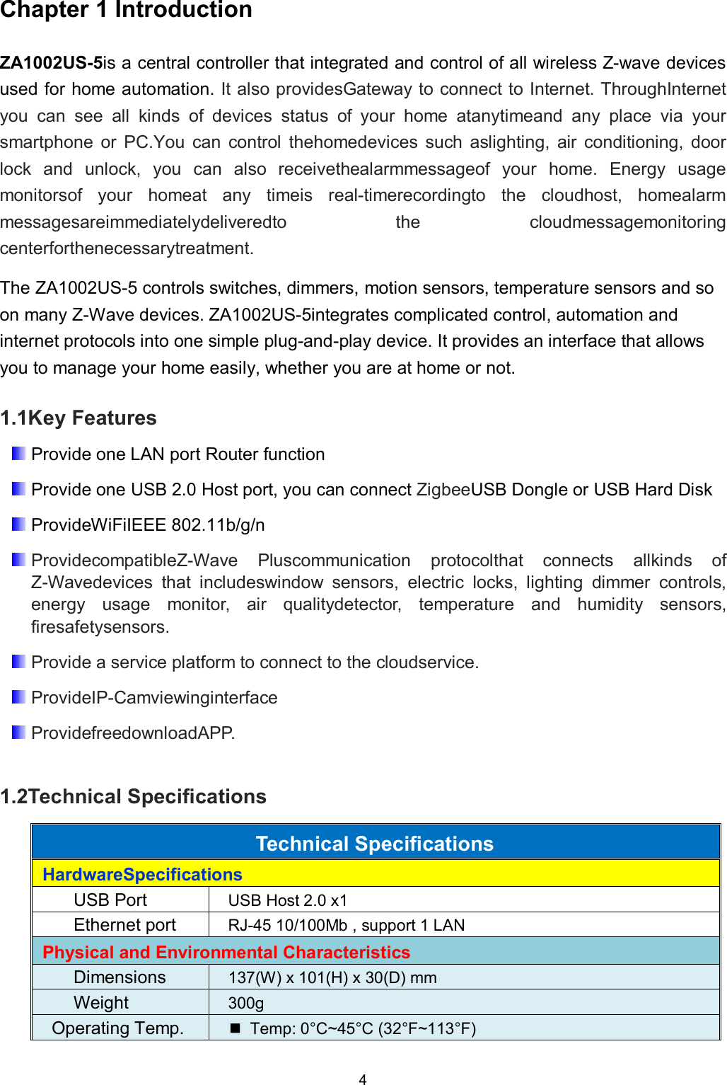
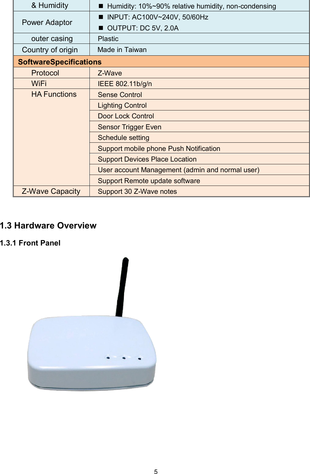
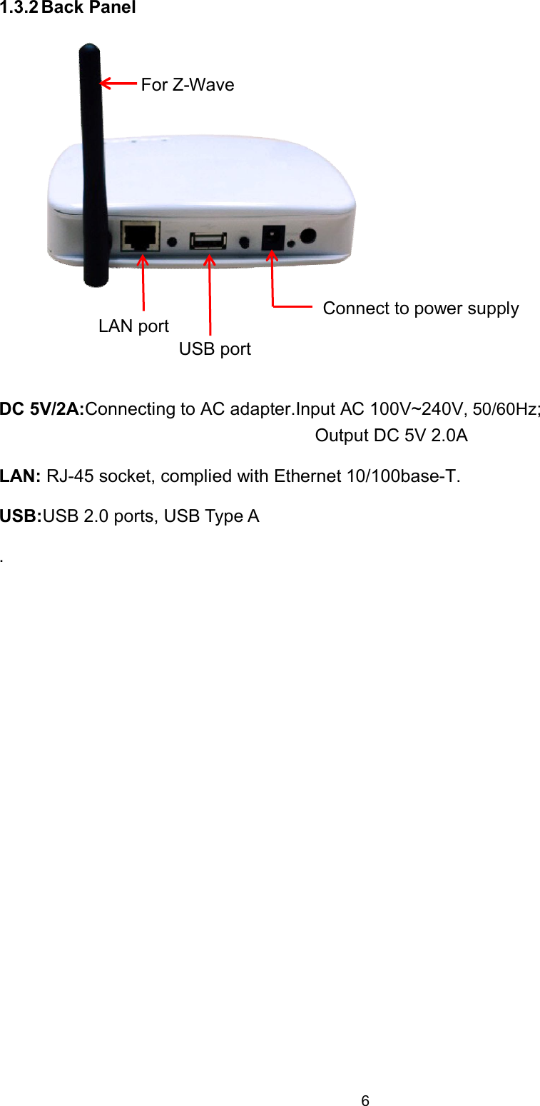
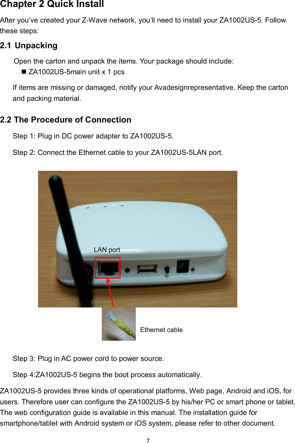
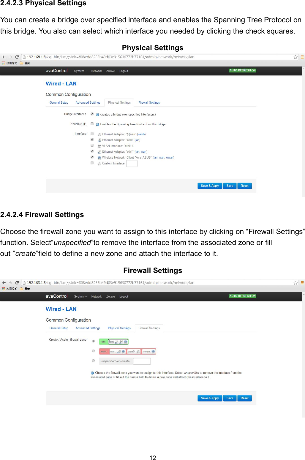
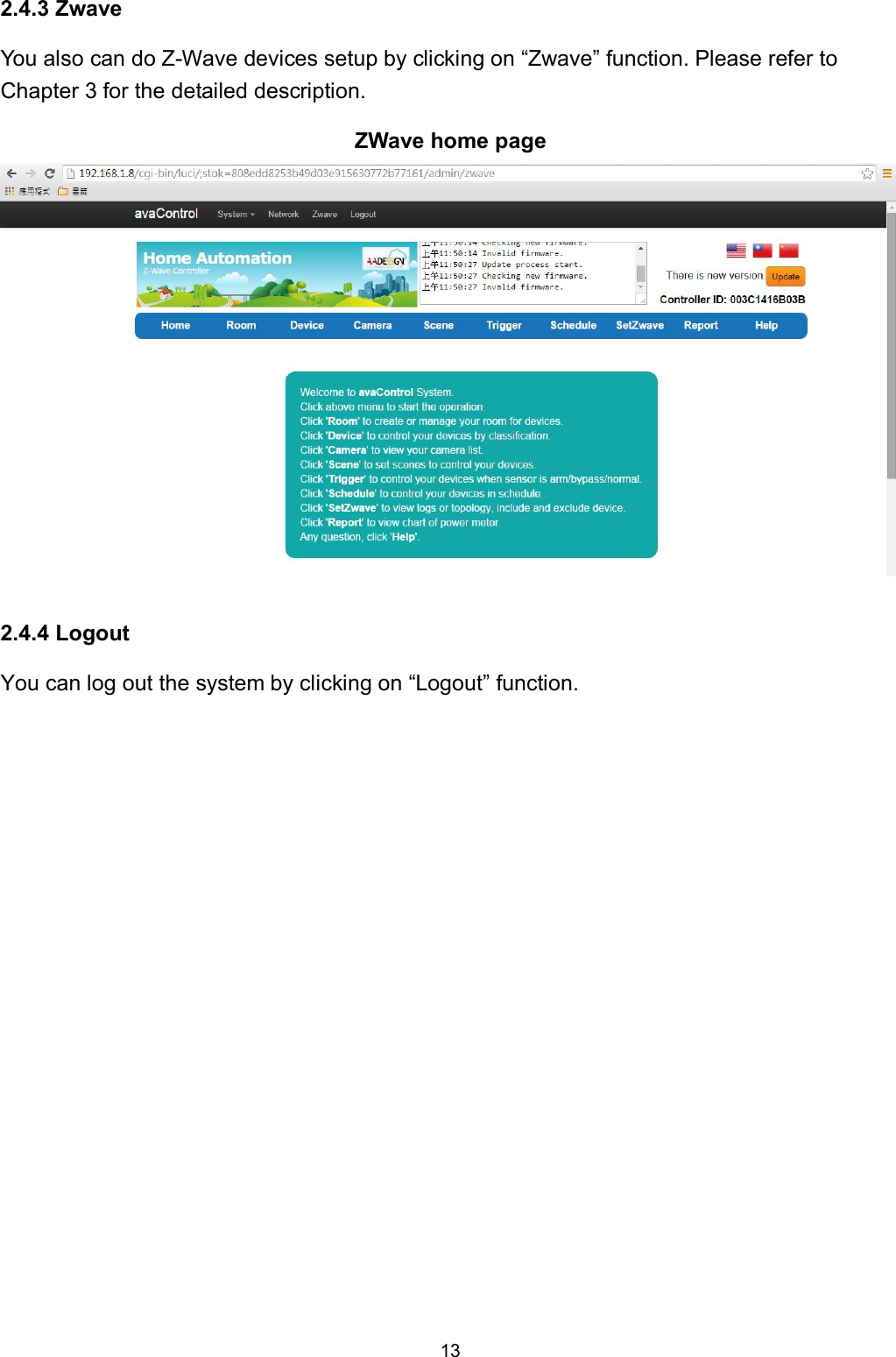
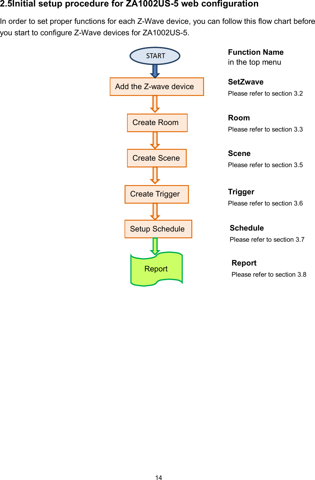
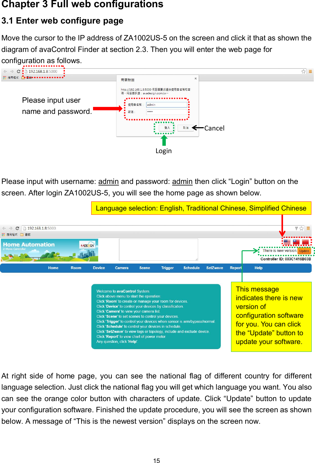
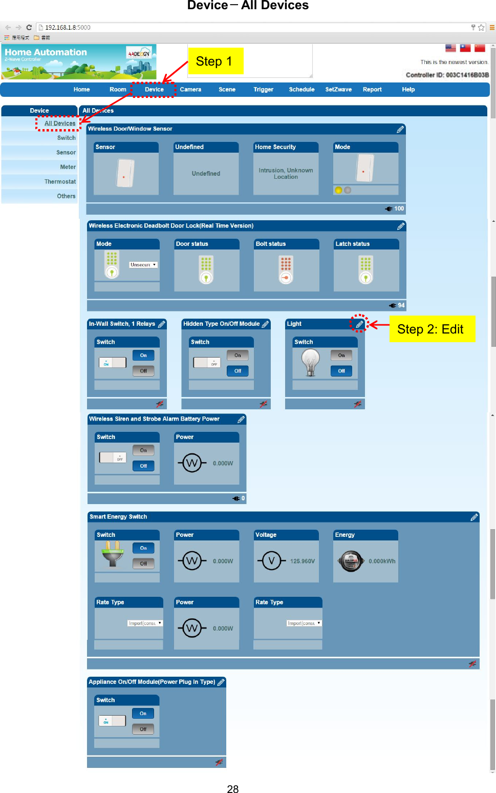
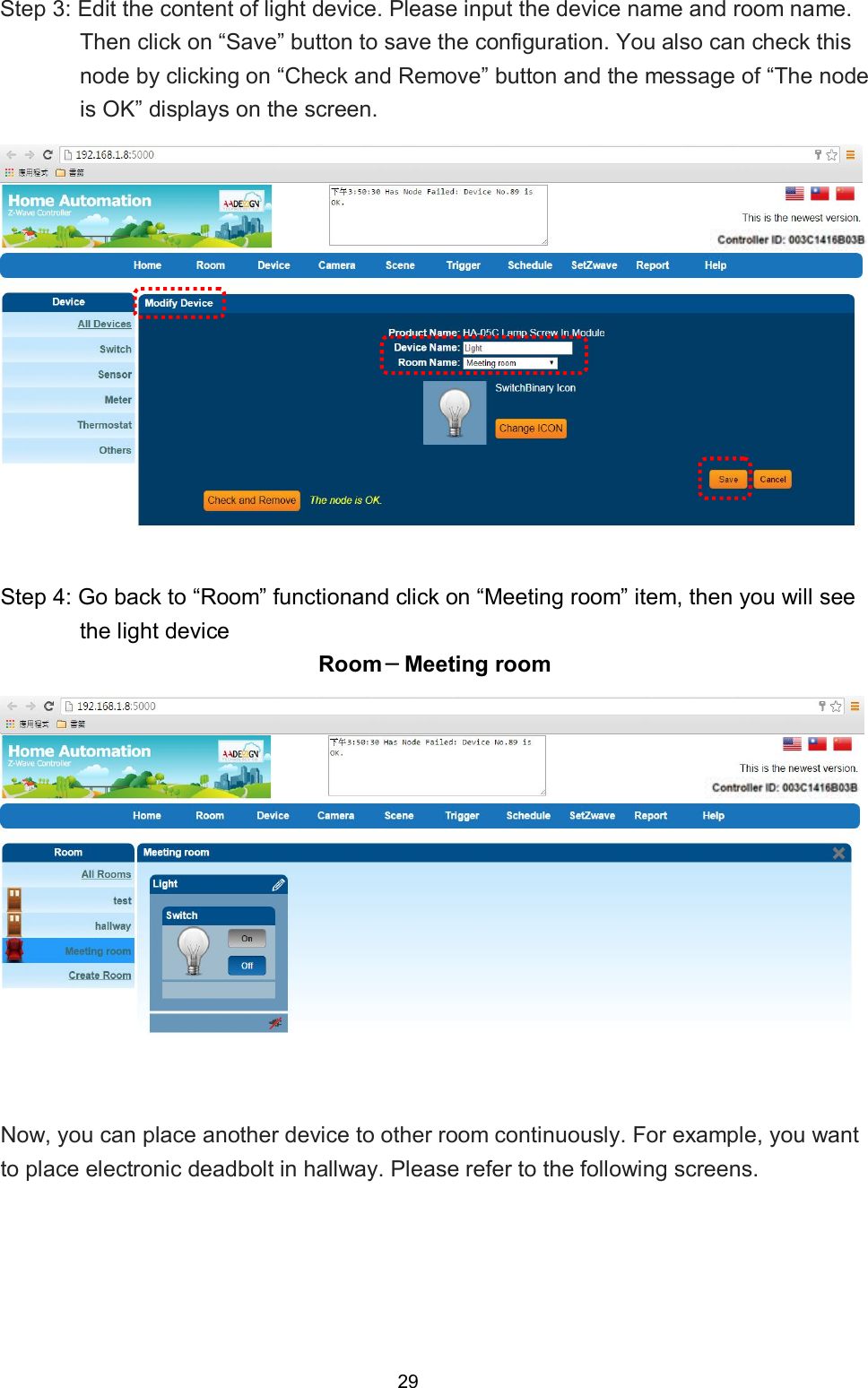
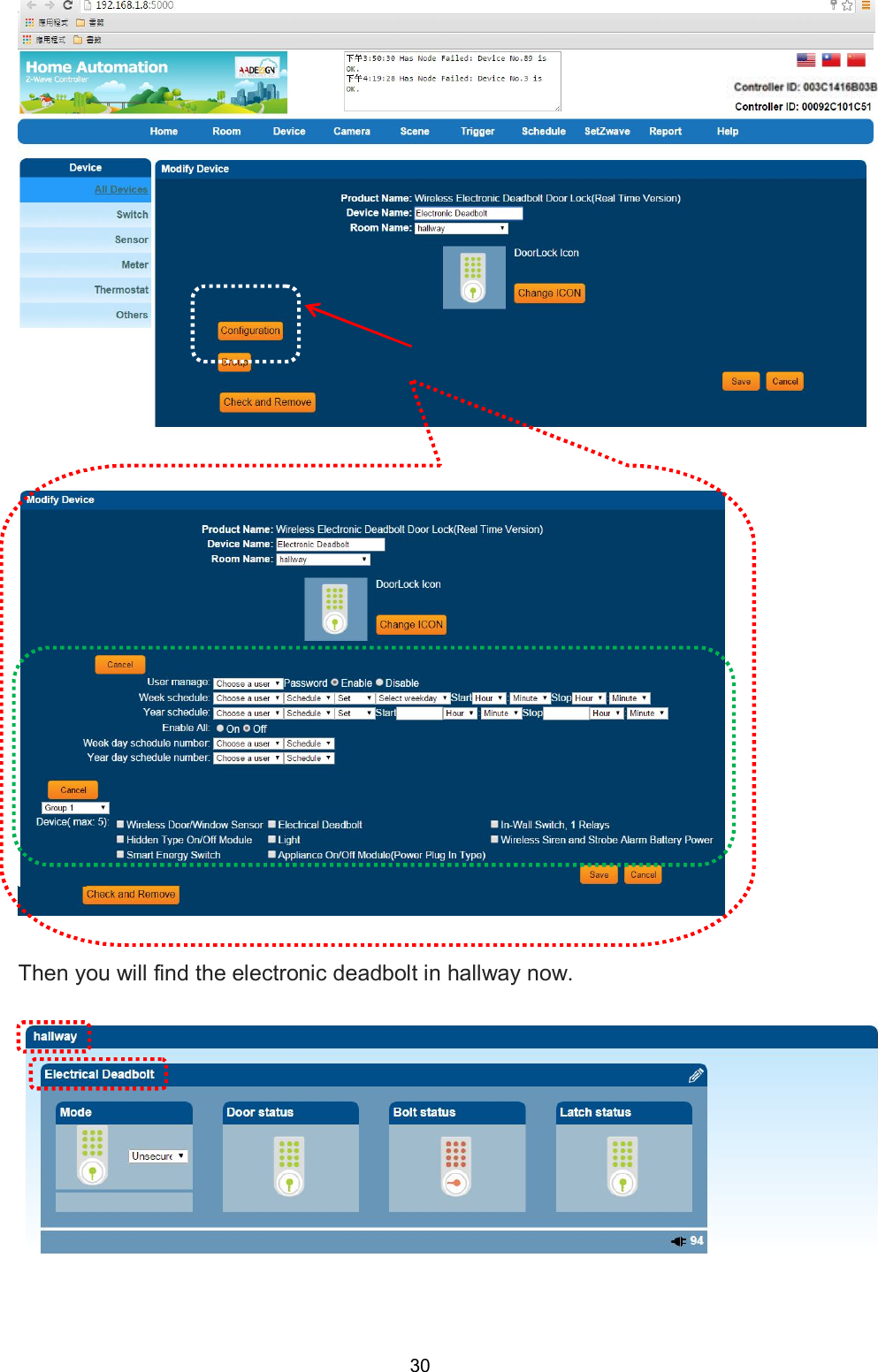
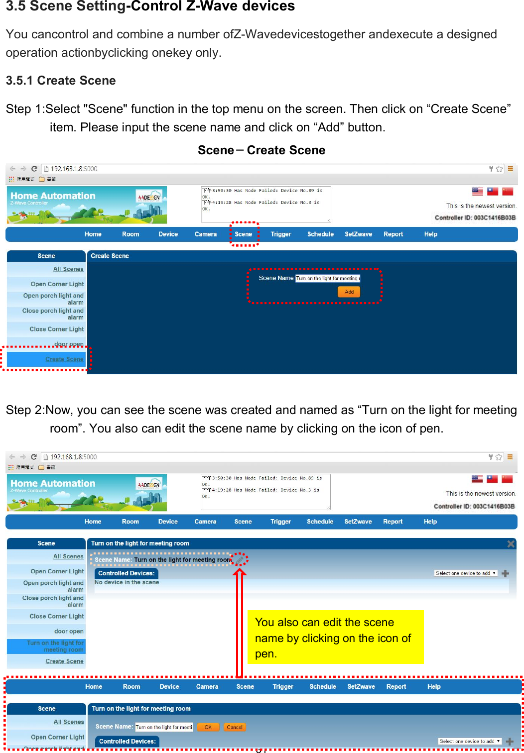
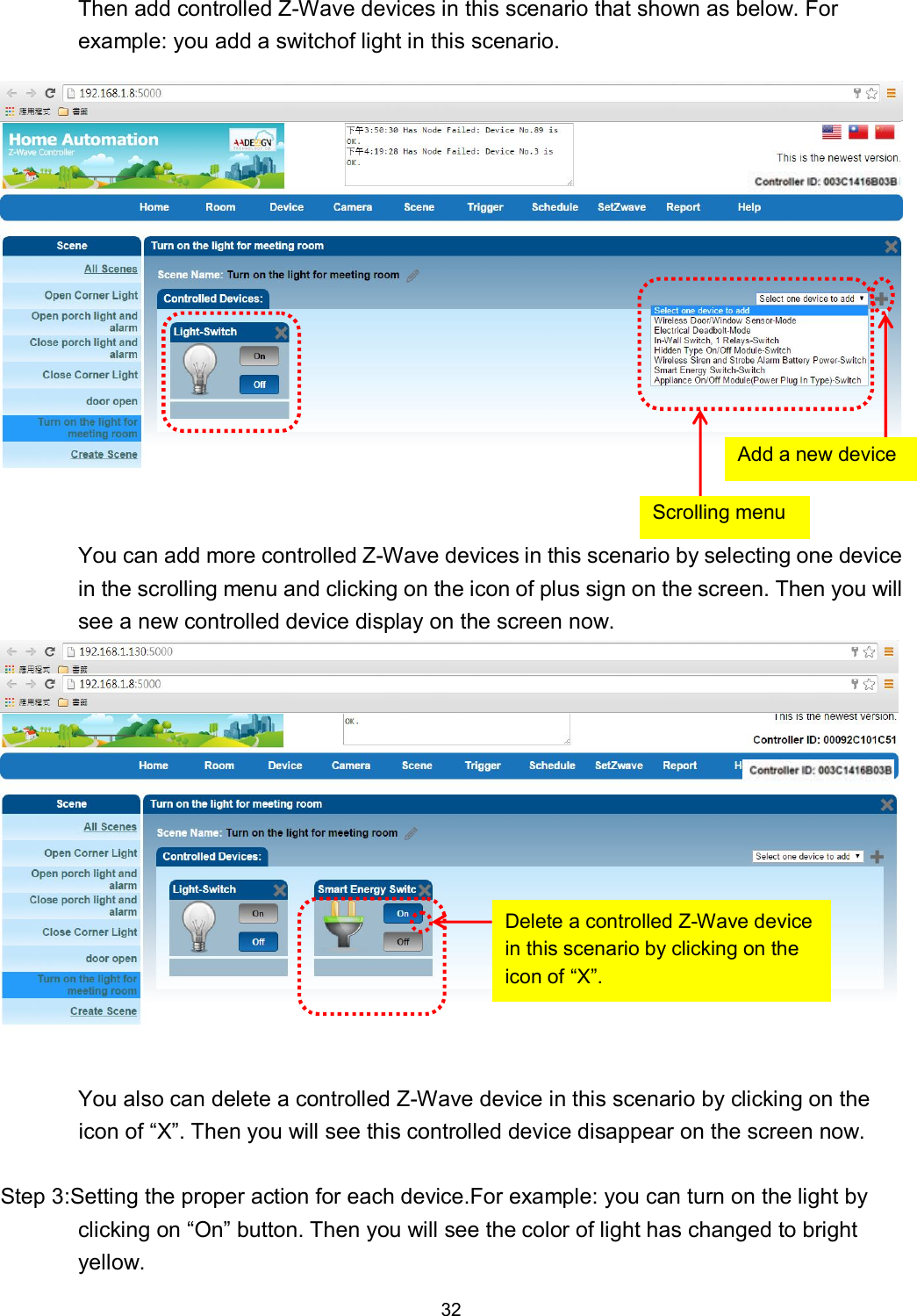
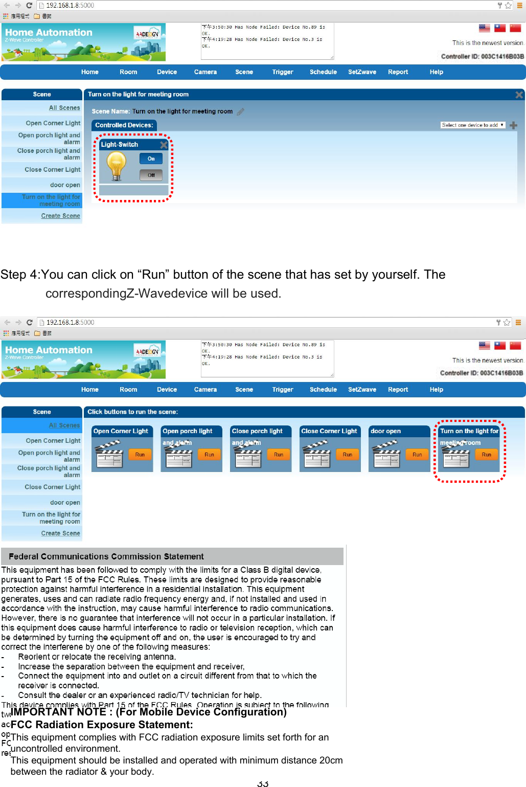
Users Manual
2.
Users Manual Revised
Users Manual
Navigation menu
Upload a User Manual
Namespaces
Wiki Guide
HTML
PDF
Info
Views
User Manual
Discussion / Help
Navigation