Vision Automobile Electronics Co ZL7435US-5 In-Wall Switch, 2Relays User Manual
Vision Automobile Electronics Industrial Co Ltd In-Wall Switch, 2Relays Users Manual
Users Manual
Federal Communications Commission Statement
This equipment has follows with the limits for a Class B digital device, pursuant to Part 15 of the FCC
Rules. These limits are designed to provide reasonable protection against harmful interference in a
residential installation. This equipment generates, uses and can radiate radio frequency energy and, if
not installed and used in accordance with the instruction, may cause harmful interference to radio
communications. However, there is no guarantee that interference will not occur in a particular
installation. If this equipment does cause harmful interference to radio or television reception, which
can be determined by turning the equipment off and on, the user is encouraged to try and correct the
interferene by one of the following measures:
-Reorient or relocate the receiving antenna,
-Increase the separation between the equipment and receiver,
-Connect the equipment into and outlet on a circuit different from that to which the receiver
is connected.
Consult the dealer or an experienced radio/TV technician for help.
This device complies with Part 15 of the FCC Rules. Operation is subject to the following two conditions:
(1) this device may not cause harmful interference, and (2) this device must accept any
interference received, including interference that may cause undersired operation.
FCC Caution: Any changes or modifications not expressly approved by the party responsible
for compliance could void the user’s authority to operate this equipment.
Limited Warranty
Vision Guarantees that every In-Wall Switch module is free from physical defects in material and
workmanship under normal use for one year from the date of purchase. If the product proves defective
during this one-year warranty period, Vision will replace it free of charge. Vision does not issue any
refunds. This warranty is extended to the original end user purchase only and is not transferable. This
warranty does not apply to : (1) damage to units caused by accident, dropping or abuse in handling, or
any negligent use; (2) units which have been subject to unauthorized repair, taken apart, or otherwise
modified; (3) units not used in accordance with instruction; (4) damages exceeding the cost of the
product; (5) transit damage, initial installation costs, removal cost, or reinstallation cost. For
information on addional devices, plesae visit us at www.visionsecurity.com.tw
ZL 7435-5
V0
1031205
6B1Z-7400A
Installation & Operation Manual
ZL7435IN-5
ZL7435MY-5
ZL7435EU-5
ZL7435RU-5
ZL7435US-5
ZL7435US-5_WIRE
ZL7435IL-5
ZL7435KR-5
ZL7435HK-5
ZL7435JP-5
ZL7435BR-5
In-Wall Switch, 2 Relays
(Screw Terminal type or Wire type)
Introduction
Thanks for choosing the Vision’s In-Wall Switch module of the home automation device. This module is
a Z-Wave™ enabled device (interoperable, two-way RF mesh networking technology) and is fully
compatible with any Z-Wave™ enabled network and it’s security framework. Every mains powered Z-
Wave enabled device acts as a signal repeater and multiple devices result in more possible
transmission routes which helps eliminate “RF dead-spots”.
Z-Wave™ enabled devices displaying the Z-Wave™ logo can also be used with it regardless of the
manufacturer, and ours can also be used in other manufacturer’s Z-Wave™ enabled networks. With
special design, this module can fit into most of electronic box in the market. This module will send
On/Off signal to the appliance that attached to this module by receiving Z-Wave™ signal from
controller. It also can control two appliances independently. When the device is secure included into Z-
Wave network, above communication will be encrypted.
Product Description and Specification
Specification:
Package Content
Protocol: Z-Wave™ (ZM5101)
1pc
ZL 7435-5 In-Wall Switch, 2
Frequency Range:
865.22MHz (ZL7435IN-5)
Relays (Screw Terminal)
868.10MHz (ZL7435M
Y
-5)
1pc
Installation & Operation
868.42MHz (ZL7435EU-5)
869.00MHz (ZL7435RU-5)
Manual
908.42MHz,916.00MHz
(ZL7435US-5,ZL7435US-5_WIRE)
916.00MHz (ZL7435IL-5)
919~923MHz (ZL7435KR-5)
919.80MHz (ZL7435HK-5)
922~926MHz (ZL7435JP-5)
921.42MHz (ZL7435BR-5)
Operating Range: Up to 100 feet line of sight
Operating Temp.: -15°C~ 60°C (5°F~140°F)
Operating Voltage: 100VAC~240VAC
Resistive Load:
550W for 110VAC
1100W for 220VAC
Z-Wave™ Command Classes:
COMMAND_CLASS_ASSOCIATION_GRP_INFO
COMMAND_CLASS_ASSOCIATION_V2
COMMAND_CLASS_CONFIGURATION
COMMAND_CLASS_DEVICE_RESET_LOCALLY
COMMAND_CLASS_FIRMWARE_UPDATE_MD_V2
COMMAND_CLASS_MANUFACTURER_SPECIFIC
COMMAND_CLASS_MULTI_CHANNEL_ASSOCIATION_V2
COMMAND_CLASS_MULTI_CHANNEL_V2
COMMAND_CLASS_POWER_LEVEL
COMMAND_CLASS_PROTECTION
COMMAND_CLASS_SECURITY
COMMAND_CLASS_SWITCH_ALL
COMMAND_CLASS_SWITCH_BINARY
COMMAND_CLASS_VERSION
COMMAND_CLASS_ZWAVEPLUS_INFO
Installation
Notice: If you are installing the entire Z-Wave™ system for the first time, please refer to the
installation guide of Z-Wave™ Interface Controller before installing ZL7435 In-Wall Switch Module.
-1-
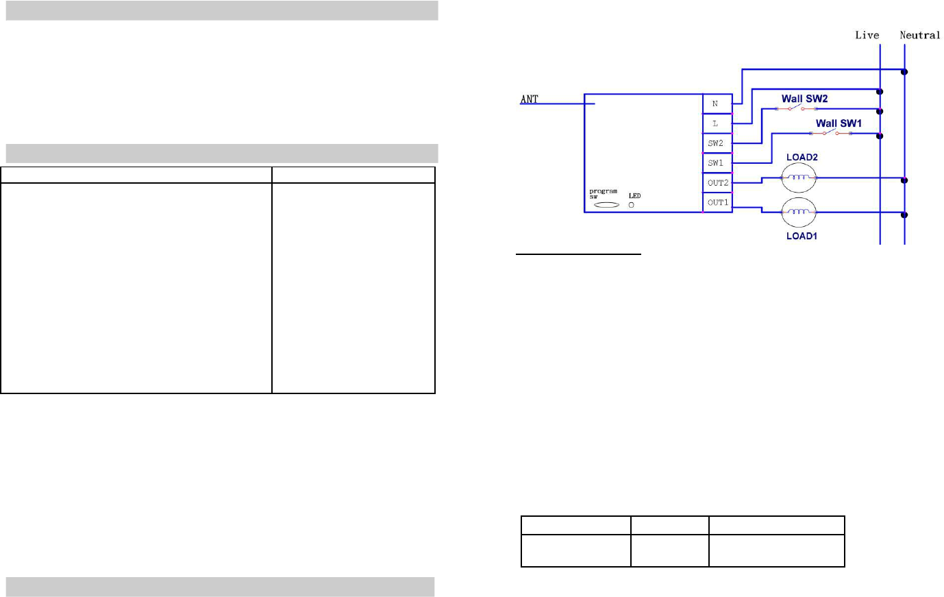
1. Following the wiring diagram to install ZL7435.
Note: Place antenna toward the surface and away from metal to get better signal.
LED Status after Power On:
Not Included: FLASH
Included
: OFF
1.
For “Inclusion” in (adding to) a network: Put the Z-Wave™ Interface Controller into “inclusion”
mode, and following its instruction to add the ZL 7435 to your controller. To get in the “inclusion”
mode, the distance between module and controller is suggested to be in one meter.
Press 3 times within 2 seconds or turn on the wall switch 3 times within 2 seconds (or press
toggle switch 3 times) to be included.
For “Exclusion” from (removing from) a network: Put the Z-Wave™ Interface Controller into
“exclusion” mode, and following its instruction to delete the ZL 7435 from your controller.
Press 3 times within 2 seconds or turn on the wall switch 3 times within 2 seconds (or press
toggle switch 3 times) to be excluded.
2.
For “Association”: Use Association to set up the reporting node after triggering for group 1
of SW1 (switch 1). Put the Z-Wave TM Interface Controller into “association”, and following its
instruction to associate the ZL7435-5 with other devices. .Support one association group (5
nodes).
For “MultiChannel Association”: Use MultiChannel Association to set up the group 2 of SW2
(switch 2) which will assign the group’s nodes or node’s endpoint.
3.
For “Button Mode Switching”: Use Command Class Configuration’s CONFIGURATION_SET
to change the button mode (switch or toggle)
Byte
Value
Parameter 1
1
0 = Switch (Default)
1 = Toggle
-2-
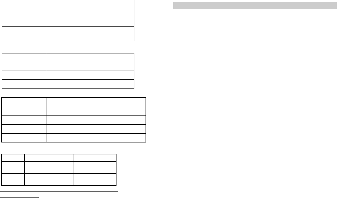
4.
For “SW1’s Protection”: Use Command Class Protection’s PROTECTION_SET to protect SW1.
Value
Protection Level
00
Normal (Default)
1
Press 4 Times On & Off To Switch On/Off Status
Only accept Z-Wave Command; such as:
2
BASIC_SET, SWITCH_ALL_ON,
SWITCH_BINARY_SET & SWITCH_ALL_OFF
5.
For “SW2’s Protection”: Use Command Class Multichannel’s MULTI_CHANNEL-
CMD_ENCAP to Encapsulate Command Class Protection’s PROTECTION_SET.
Value
Protection Level
0
Normal (Default)
1
Press 4 Times On & Off To Switch On / Off Status
2
Only accept Z-Wave Command
6.
For “SWITCH_ALL_ON”: Use SWITCH_ALL_SET to control all on or all off
Value
Status
0xFF
Accept SWITCH_ALL_ON & SWITCH_ALL OFF (Default)
0x00
No accept SWITCH_ALL_ON & SWITCH_ALL OFF
0x01
Only accept SWITCH_ALL OFF
0x02
Only accept SWITCH_ALL_ON
7.
For “SW1’s Control”: Press SW1 to control 1
st
Relay’s On & Off.
Value
Status
ON
Binary Switch Set (0xFF)
Basic Set On
Switch All On
OFF
Binary Switch Set (0x00)
Basic Set Off
Switch All Of
f
For relay 1 or 2: Please use Multi-Channel command class to control
8.
Factory Default Reset: Power off first, press Program Switch and power on till 10 seconds,
ZL7435 will send the “Device Reset Locally Notification” command and reset to the factory default.
(Remark: This is to be used only in the case of primary controller being inoperable or otherwise
unavailable.)
9.
Support OTA Firmware update from controller. Please refer to your controller manual. We
recommend to exclusive the device & include again before use the device.
10.
Support AES Function.
-3 -
11.
All the rest commands depend on Z-Wave standard.
Operation
Turn on or turn off two individual appliances that attached to ZL7435 by Z-Wave™ Interface Controller
-4-