Visionary RDX RADIATION DETECTION DEVICE User Manual V019231 05AD Rad DX Manualx
Visionary Products, Inc. RADIATION DETECTION DEVICE V019231 05AD Rad DX Manualx
Users Manual
INSTALLATION AND OPERATING
INSTRUCTIONS FOR THE
RADIATION DETECTION SYSTEM
D-tect Systems Group
Visionary Products Inc.
11814 South Election Road, Suite 200
Draper, UT 84020
www.dtectsystems.com

6/12/2012, Rad-DX Manual Version 2.0 Page 2
Table of Contents
1 Introduction.............................................................................................................................. 3
2 System Components ................................................................................................................ 3
3 Networking Options Overview ................................................................................................ 5
4 Monitoring and Controlling the DX using the LCD Screen .................................................... 7
4.1 Explanation of Networking Icons on the LCD Touch Screen ........................................ 8
5 Monitoring and Controlling the Rad-DX in a Network using the DX Dashboard .................. 9
5.1 Signing In ........................................................................................................................ 9
5.2 Home Screen ................................................................................................................. 10
5.2.1 Home Screen Buttons ............................................................................................... 13
5.2.2 Settings Button ......................................................................................................... 13
5.2.3 Help Button ............................................................................................................... 14
5.3 Radiation Level Graph Button ...................................................................................... 15
5.4 Device Configuration Button ........................................................................................ 16
5.4.1 Device Tab ................................................................................................................ 16
5.4.2 Properties Tab ........................................................................................................... 17
5.4.3 Alarm Tab ................................................................................................................. 18
5.4.4 Ethernet Tab ............................................................................................................. 19
5.4.5 WiFi Tab ................................................................................................................... 20
5.4.6 Mesh Tab .................................................................................................................. 21
5.4.7 Firmware Update Tab ............................................................................................... 22
6 Installation and Set-up of your Rad-DX ................................................................................ 23
6.1 Physical Installation ...................................................................................................... 23
6.1.1 Junction Box Method ................................................................................................ 23
6.1.2 Plug-In Wall Mount Method .................................................................................... 24
6.2 Installing a DX network using the D-tect Cloud Network ............................................ 25
6.2.1 User Name and Password ......................................................................................... 25
6.2.2 DX Utility Application Installation Instructions ...................................................... 25
7 Specifications ......................................................................................................................... 31
8 Technical Support .................................................................................................................. 32
Warranty for D-tect System Products ............................................................................................. 34
6/12/2012, Rad-DX Manual Version 2.0 Page 3
1 Introduction
The Rad-DX is a security and inspection system that detects emissions from radioactive material.
The Rad-DX system can operate as a stand-alone detector or as part of a larger rad-DX network
monitoring a building or facility.
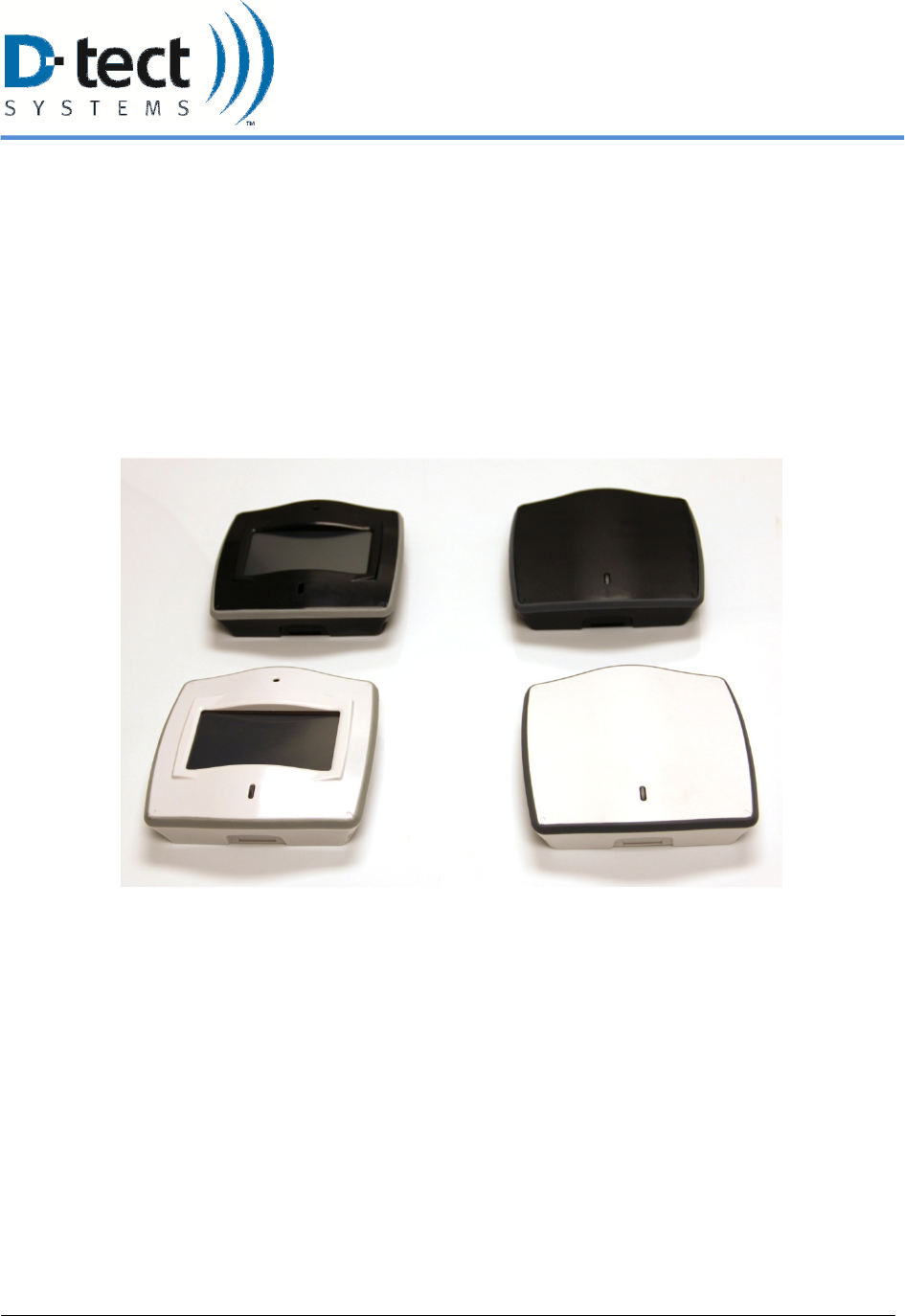
2 System Components
There are several configurations available for a Rad-DX system. Four styles are available: black
with LCD, black without LCD, white with LCD, and white without LCD.
Figure 1: Rad-DX Versions - black and white, LCD and non-LCD
6/12/2012, Rad-DX Manual Version 2.0 Page 4
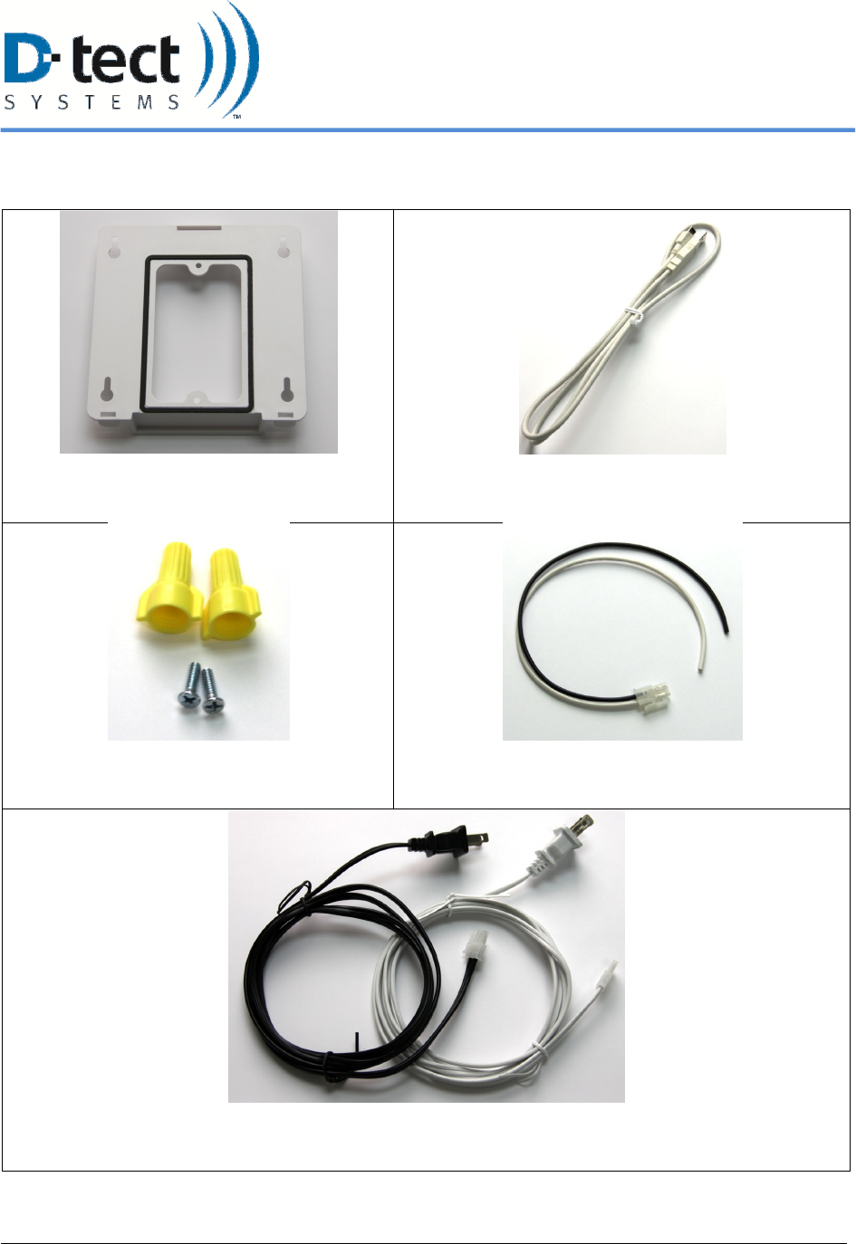
Other hardware components included with each Rad-DX include:
Mounting Bracket
USB Cable
Wire Nuts and Mounting Screws
“Pigtail” Wire Harness
Power Cable (black or white depending on color of Rad-DX)
Table 1: Additional Rad-DX Hardware

6/12/2012, Rad-DX Manual Version 2.0 Page 5
3 Networking Options Overview
Your Rad-DX can operate in a variety of configurations. Each Rad-DX unit can function as a
stand-alone unit or form part of a radiation detector network with other Rad-DX units.
Configuration options are:
Stand-Alone Operation: The Rad-DX can be controlled and monitored via the touch-screen
LCD on the unit.
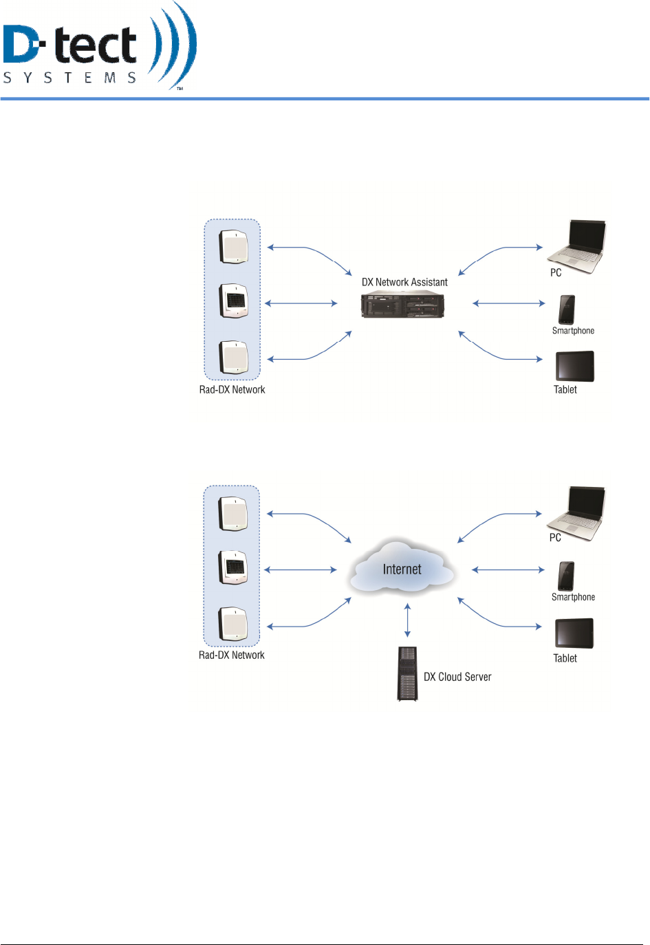
D-tect Cloud Network: The D-tect Cloud Network is the easiest method to control and monitor
a network of Rad-DX detectors. It also allows the detectors to be monitored via smartphone,
tablet, or PC. Setting up your Rad-DX unit within the Cloud Network will require a PC with an
internet connection. All information sent over the Cloud is SSL encrypted.
DX Network Assistant Appliance: Our Rad-DX Assistant appliance allows a RAD-DX
network to operate behind a firewall that blocks access to the internet. The DX Network
Assistant is a computer pre-loaded with all the software needed to control and monitor a network
of Rad-DX detectors. Installation of the network is quick and very easy. Locate the DX Network
Assistant anywhere in your facility.
6/12/2012, Rad-DX Manual Version 2.0 Page 6
DX Networking Options
DX Network Assistant
DX Cloud Server
6/12/2012, Rad-DX Manual Version 2.0 Page 7
4 Monitoring and Controlling the DX Using the LCD Screen
The Rad-DX can operate in a stand-alone mode with information displayed on the LCD display.
Options for the Rad-DX, such as display types and radiation units, can be set up by the following
process:
1. Connect the Rad-DX device to a power source, either with the A/C plug or wiring it directly
to the junction box (see Physical Installation, Section 6.1)
2. The following screen will appear on the LCD screen as the Rad-DX boots.
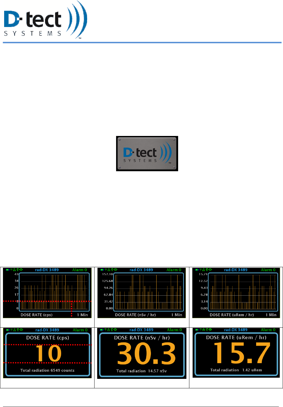
3. The Dose Rate Screen will appear on the LCD screen after loading is complete.
4. The red lines indicate the touch zone areas of the screen types below.
o Touching the total dose location will reset the total dose to zero.
o To change the time frame on the Bar Graph and Line Graph screens, touch the time
period to toggle between 1 minute, 6 minute, and 30 minute time frames.
o To change the units on the screen, touch the unit text. The units will automatically use
metric prefixes (nano, micro…) depending on the currently measured dose rate.
5. To toggle through the different screens, touch anywhere else on the screen.
Bar Graph (cps)
Bar Graph (nSv/hr)
Bar Graph (uRem/hr)
Dose Rate (cps)
Dose Rate (nSv/hr)
Dose Rate (uRem/hr)
Table 2: LCD Screen Shots: Dose Rate and Bar Graph (CPS, nSv/hr, and uRem/hr)
6/12/2012, Rad-DX Manual Version 2.0 Page 8
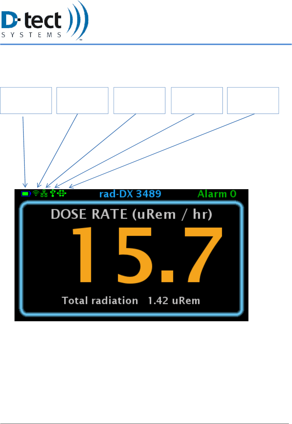
4.1 Explanation of Networking Icons on the LCD Touch Screen
The appearance of any network connection icon indicates that the device is currently connected via the
referenced connection.
WiFi
Connection
Battery Level USB
Connection
Mesh Network
Connection
Ethernet
Connection
Figure 2: LCD Screen
6/12/2012, Rad-DX Manual Version 2.0 Page 9
5 Monitoring and Controlling the Rad-DX in a Network Using the
DX Dashboard
The DX Dashboard software is used to monitor and control a Rad-DX network. It runs on either
the D-tect Cloud server or the DX Network Assistant (if you've installed it at your facility).
Using the DX Dashboard, you can access your Rad-DX network using any web-enabled device
(smartphones, tablets, PCs). You will be asked for your user name and password to allow access
to your network (see Section 6.2).
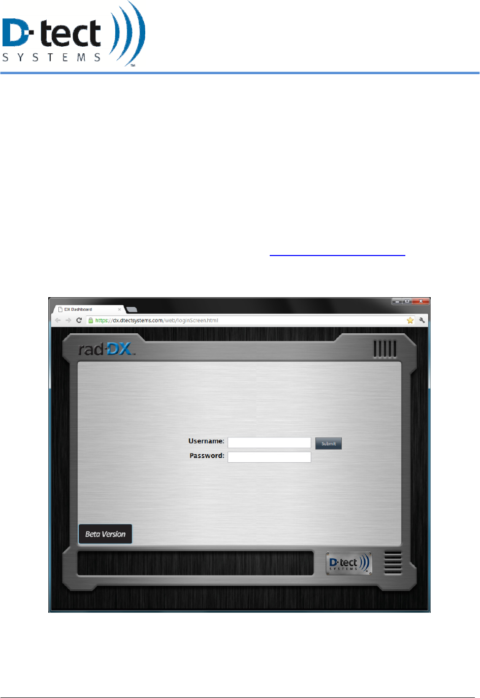
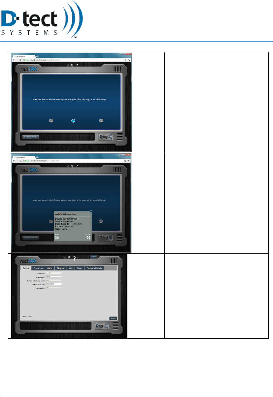
5.1 Signing In
If your network is on the D-tect Cloud Network, go to https://dx.dtectsystems.com on your smart
device or computer’s internet browser and enter your user name and password. If your network is
local, go to the URL of your DX Network Assistant and enter your user name and password.
Figure 3: Rad-DX Sign-in Screen
6/12/2012, Rad-DX Manual Version 2.0 Page 10
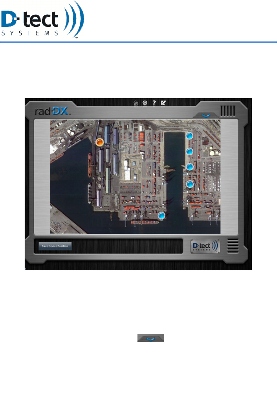
5.2 Home Screen
When you open the DX Dashboard on a PC, smartphone, or tablet and log in, the Home screen
will be the first displayed. The Home screen will show a map or a blueprint and where the Rad-
DX units are located. (See Section 5.2.2 to upload a map or blueprint)
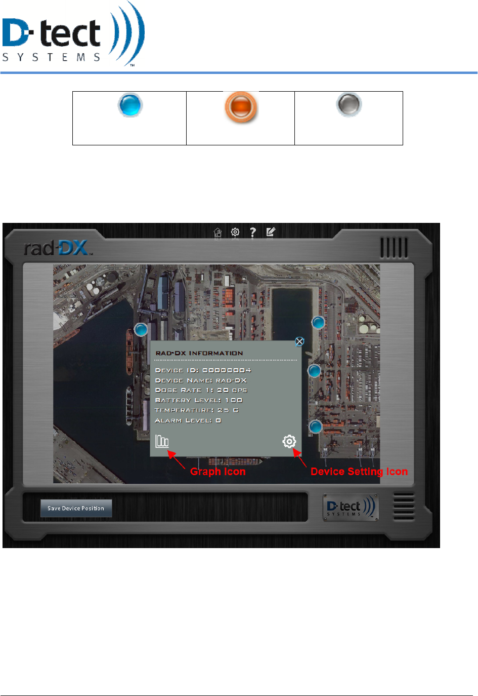
Figure 4: Application Home Screen with one alarming device icon and five normal device icons
During normal operation, each Rad-DX device in the network will appear as a small blue button.
For the real-time dose rate measurement and device settings, click the button for the detector you
want to see. A grey device window will pop up containing information about the unit. To access
a graph of the current detection values, click on the white Radiation Level Graph button at the
bottom left of the screen (see Section 5.3). To change the settings on the device, click the white
gear Device Configuration button (see Section 5.4) at the bottom right of the screen (see Figure
5). To see a summary of all detectors, click the button found in the top left (see Figure
6).
6/12/2012, Rad-DX Manual Version 2.0 Page 11
Normal
(non-alarming) device
Alarming device
Non-operational or
disconnected device
Table 3: Device Icons
Figure 5: Device Window containing information about a specific Rad-DX device. The Radiation Level
Graph button (see Section 5.3) and Device Configuration button (Section 5.4) are labeled.
6/12/2012, Rad-DX Manual Version 2.0 Page 12
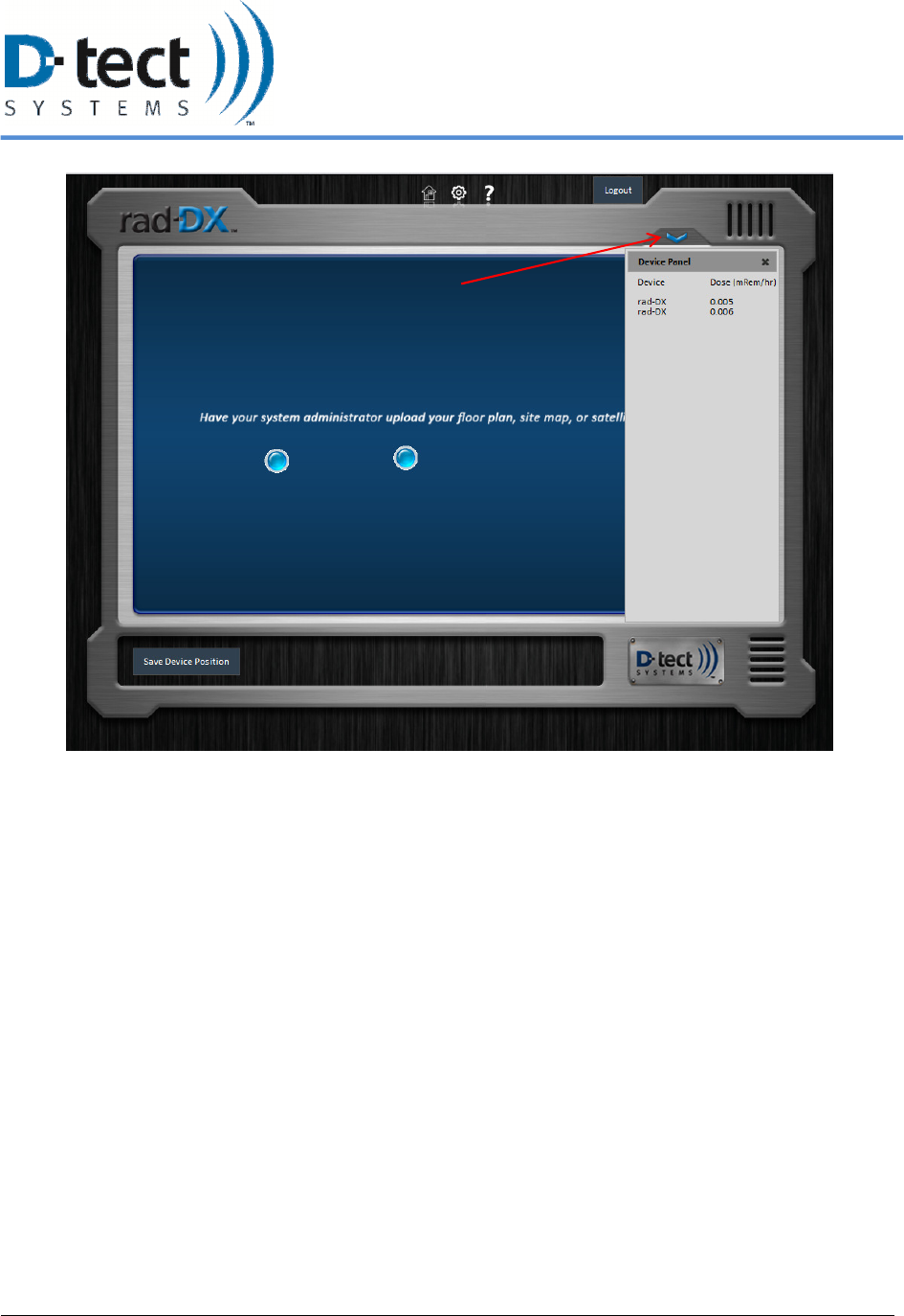
Figure 6: The Device Panel reveals a list of all Rad-DX detectors with dose rate information.
Click Blue Arrow to reveal
Device Panel
6/12/2012, Rad-DX Manual Version 2.0 Page 13
5.2.1 Home Screen Buttons
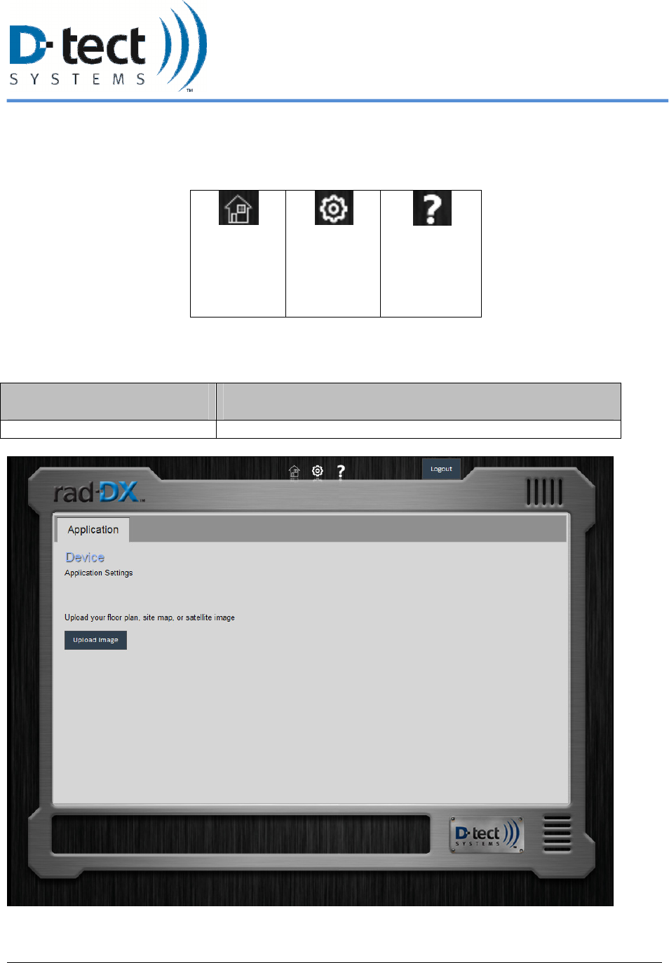
At the top of the Home screen there are three buttons.
Home
Section
5.2.1
Settings
Section
5.2.2
Help
Section
5.2.3
Table 4: Additional Rad-DX Hardware
5.2.2 Settings Button
Application Tab Options Function
Upload Image Allows user to upload floor plan, site map, or satellite image
Figure 7: Application Tab
6/12/2012, Rad-DX Manual Version 2.0 Page 14
To Upload a Map or Blueprint
Any map or blueprint in jpeg, bmp, png, or tif formats can be uploaded. To upload the map or
blueprint of your location:
1. Select the Settings icon on the top of the Home screen.
2. Select the Upload Map/Blueprint button.
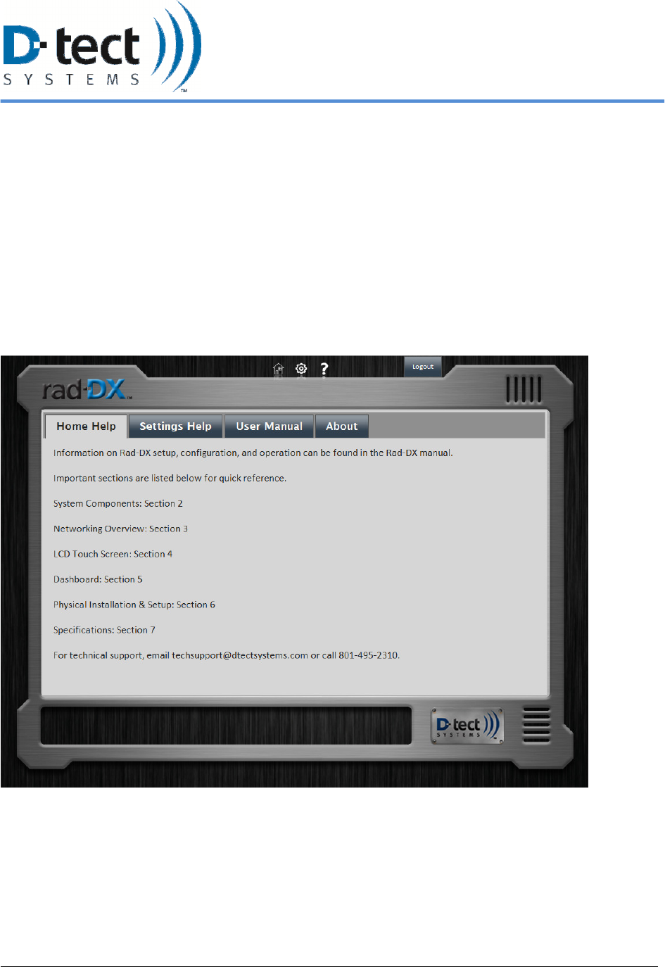
5.2.3 Help Button
The Help screen will provide information similar to this manual to explain features and
functions.
Figure 8: Help Screen
6/12/2012, Rad-DX Manual Version 2.0 Page 15
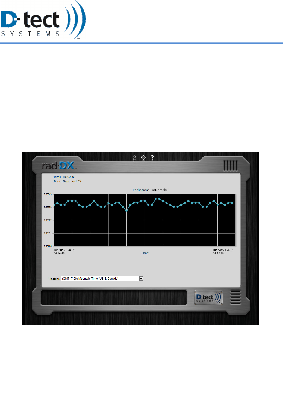
5.3 Radiation Level Graph Button
To see a graph of the current dose rate detected by the unit, follow these steps:
1. Access the Home Screen on DX Dashboard
2. Click on the Rad-DX icon to access the gray Device Configuration Window
3. Click on the small white Graph Icon on the bottom right of the Device Configuration Window
4. The graph will display recent dose rate readings detected by the unit
5. The user may change the Radiation units at the top of the screen from mRem/hr to µSv/hr to CPS
by clicking directly on the current radiation unit being displayed.
6. The user may change the time zone by clicking on the dropdown menu to select the desirable
time zone.
Figure 9: Radiation Graph
6/12/2012, Rad-DX Manual Version 2.0 Page 16
5.4 Device Configuration Button
To configure a specific Rad-DX device, select the corresponding blue icon on the Home Screen.
A small grey box will pop up with information on the device. Click the Device Settings Icon
(small white gear) at the bottom right of this box to access the configuration settings. The
following tabs allow customization in these areas:
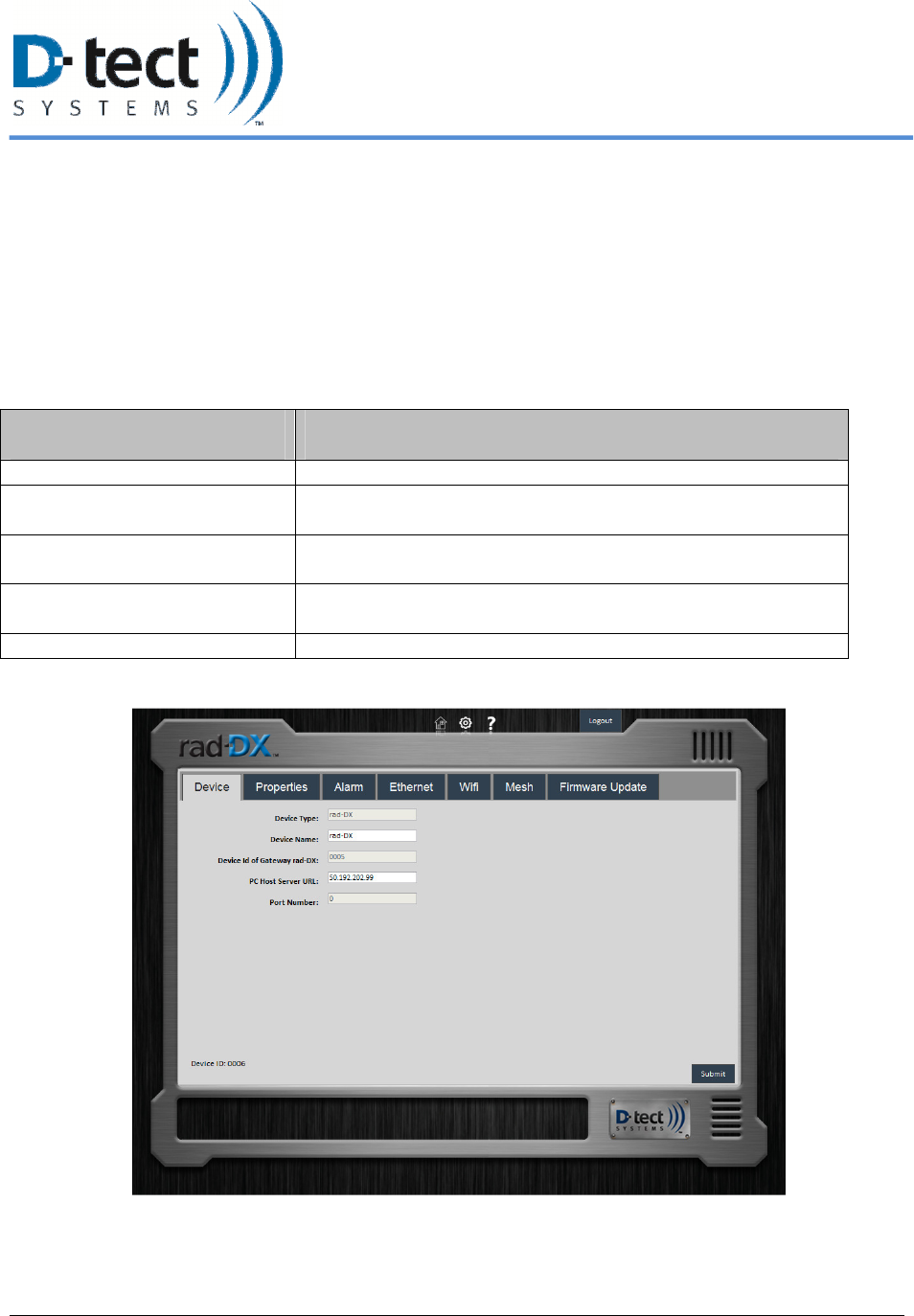
5.4.1 Device Tab
Device Tab Options Function
Device Type Lists the D-tect Systems device that the application manages
Device Name Allows the user to assign names to different devices in the
network
Device ID of Gateway Rad-DX Lists the gateway Rad-DX unit that is currently connected to
the assistant or cloud.
PC Host Server URL The URL address of the PC receiving data from the Gateway
Rad-DX device
Port Number Lists the Port Number
Figure 10: Device Tab
6/12/2012, Rad-DX Manual Version 2.0 Page 17
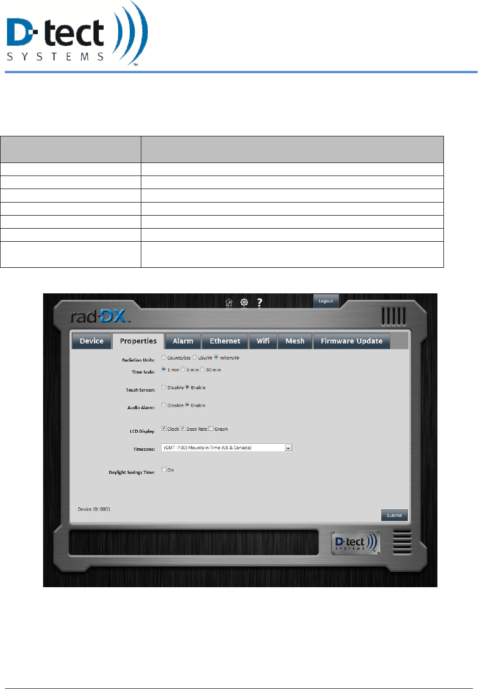
5.4.2 Properties Tab
The user can make display changes to the LCD screen on the device in the Properties Tab.
Properties Tab Options Function
Radiation Units Changes Radiation Units displayed (mRem/hr - µSv/hr - CPS)
Time Scale Changes the graph scale
Touch Screen Enables/disables touch screen on device
Audio Alarm Allows user to disable/enable the audio alarm
LCD Display Changes available screen view
Timezone Sets time zone for device
Daylight Savings Time User must check when daylight savings time adjustment is
required
Figure 11: Properties Tab
6/12/2012, Rad-DX Manual Version 2.0 Page 18
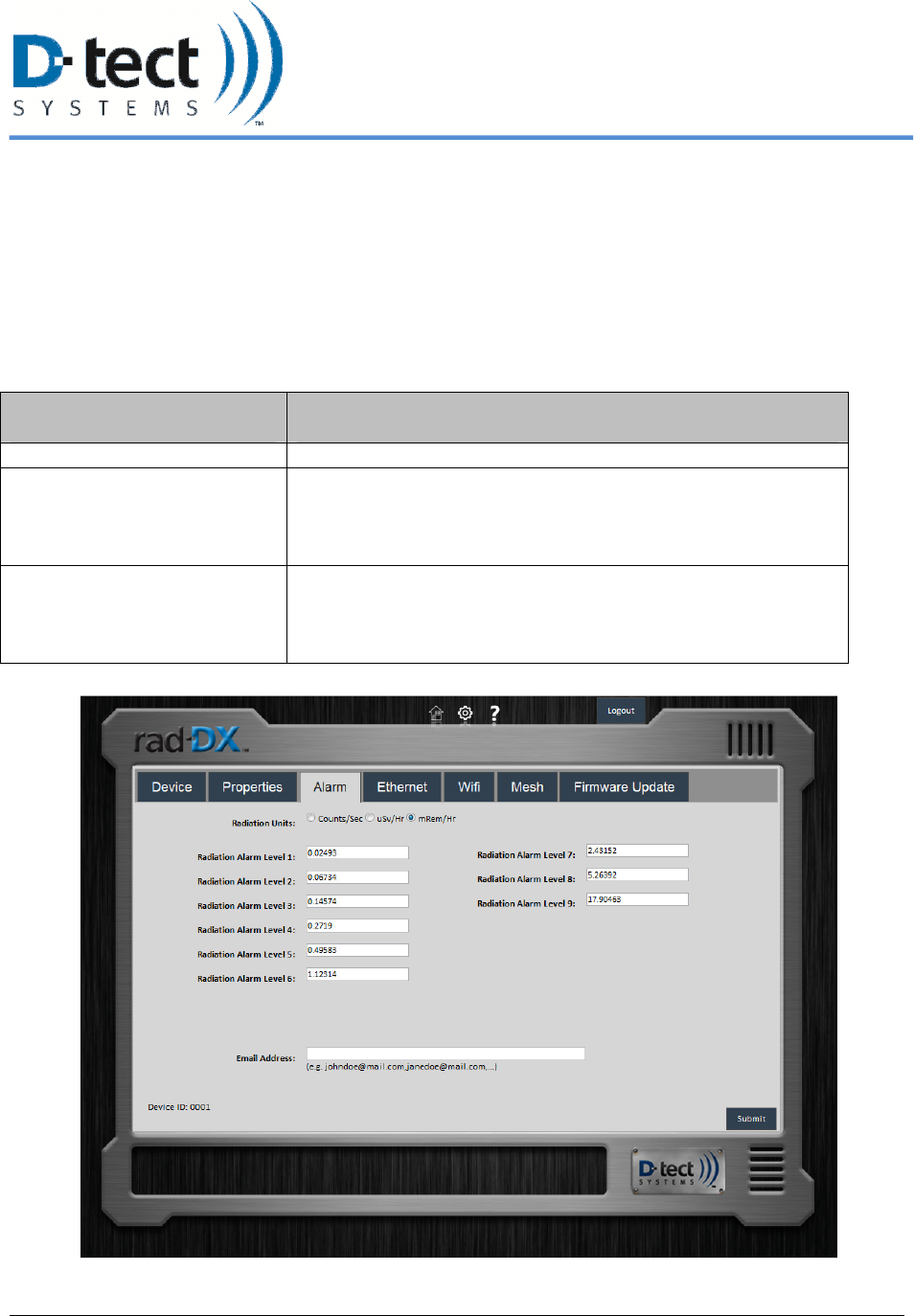
5.4.3 Alarm Tab
The user can select the radiation level that sets off an alarm. There is a scale of alarm levels from
1-9 that can be selected. This allows personnel not familiar with radiation units to be trained to
respond to simple alarm levels. To change these levels, click on the device icon on the home
screen, accessing the grey device window. Click on the white gear icon at the bottom right to
open the screen below. Under the Alarm tab, the alarm levels can be entered. The units for alarm
levels are in mRem/hr, µSv/hr, and counts per second.
Alarm Tab Options Function
Radiation Units: Changes Radiation Units displayed (mRem/hr - µSv/hr - CPS)
Radiation Alarm Levels (1-9) With units set on the Settings tab, these variable alarm levels
are set by the user with 1 as the lowest alarm level and 9 as the
highest. These levels should all be set above background levels
to minimize false positive readings.
Email Address User may add email addresses to send notifications when alerts
occur. The user may add multiple email addresses by
separating each email address with a comma, e.g.
johndoe@gmail.com,janedoe@gmail.com.
Figure 12: Alarm levels are listed and editable under the Alarm Tab
6/12/2012, Rad-DX Manual Version 2.0 Page 19
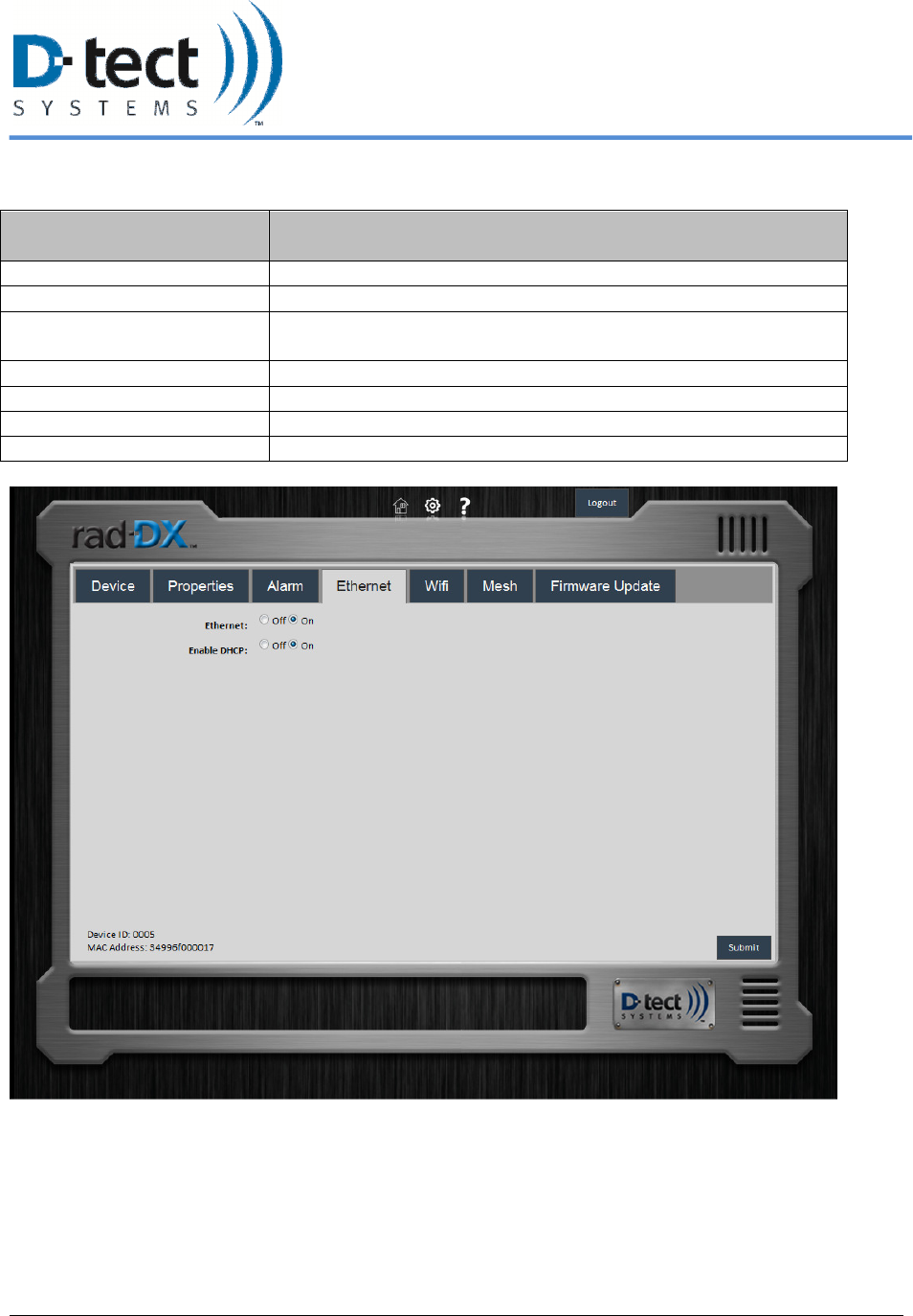
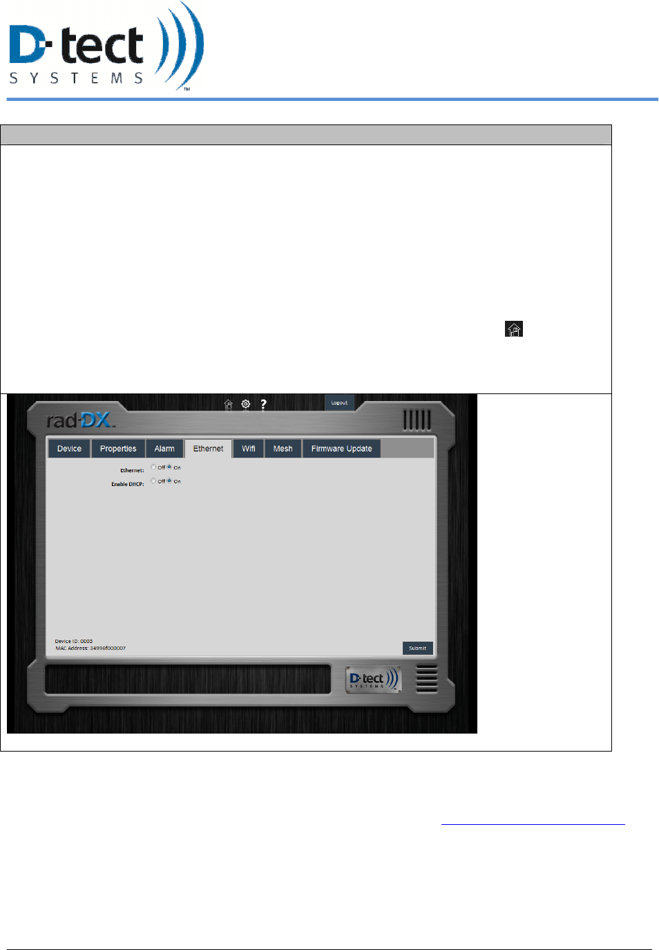
5.4.4 Ethernet Tab
Ethernet Tab Options Function
Ethernet: on/off Turns Ethernet communications on or off
Enable DHCP Enables or disables DHCP coverage
Device IP Address (static IP) Lists the static IP address set by the user when setting up the Rad-
DX network for the first time
Subnet Mask Lists the subnet mask
Gateway Lists the gateway IP address
Primary DNS Lists the primary DNS address
Secondary DNS Lists the secondary DNS address
Figure 13: Ethernet Tab
6/12/2012, Rad-DX Manual Version 2.0 Page 20
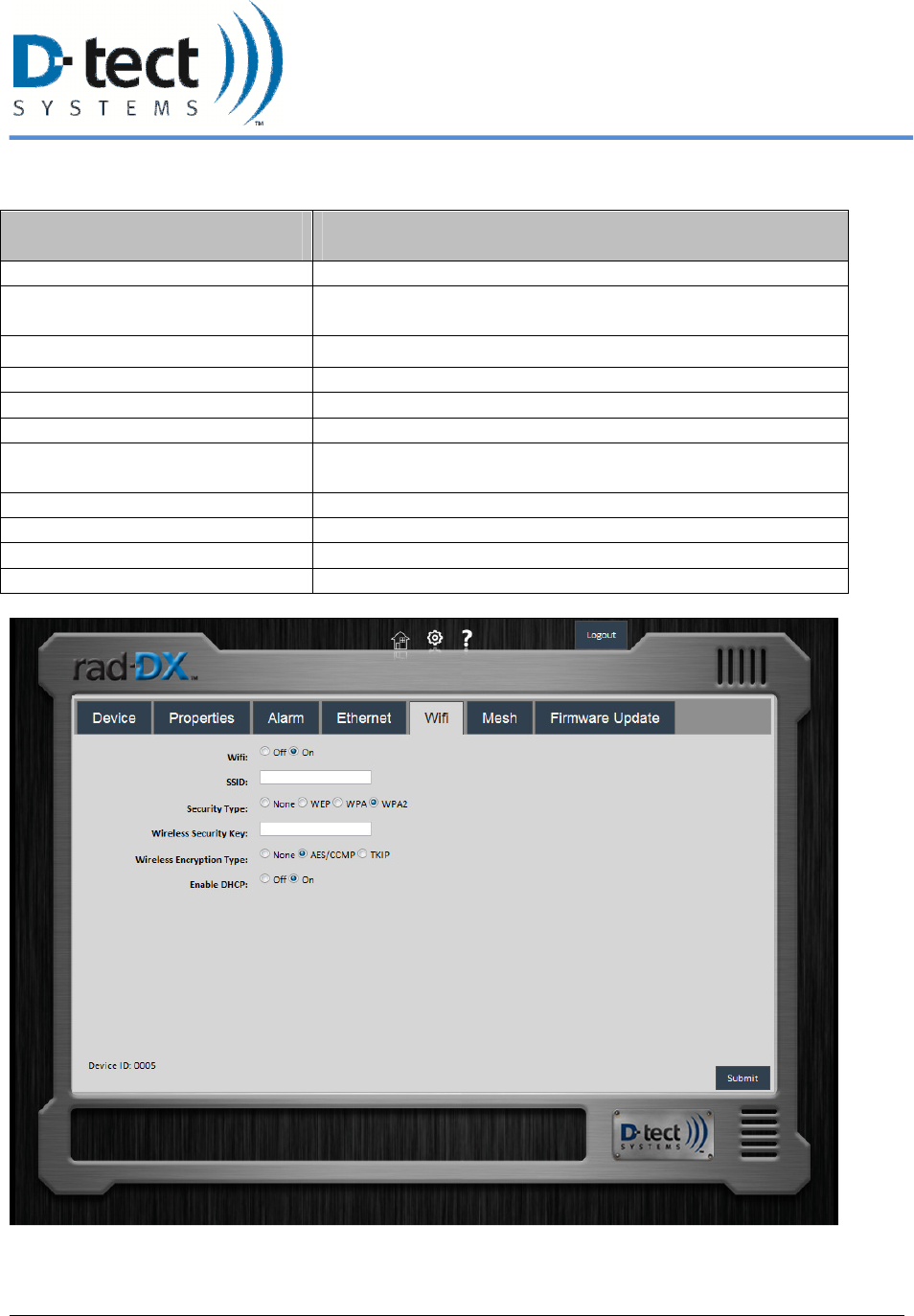
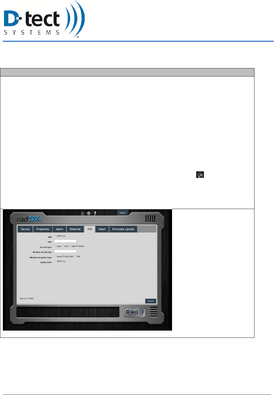
5.4.5 WiFi Tab
WiFi Tab Options Function
WiFi: on/off Turns WiFi communications on or off
SSID Lists the Service Set ID number of the WLAN device in
communication
Security Type Sets the wireless security type
Wireless Security Key The WiFi key required to communicate over the system
Wireless Encryption Type Sets the wireless encryption type
Enable DCHP Enables or disables DCHP
Device IP Address Lists the static IP address set by the user when setting up the
Rad-DX network for the first time
Subnet Mask Lists the subnet mask address
Gateway Lists the gateway IP address
Primary DNS Lists the primary DNS address
Secondary DNS Lists the secondary DNS address
Figure 14: WiFi Tab
6/12/2012, Rad-DX Manual Version 2.0 Page 21
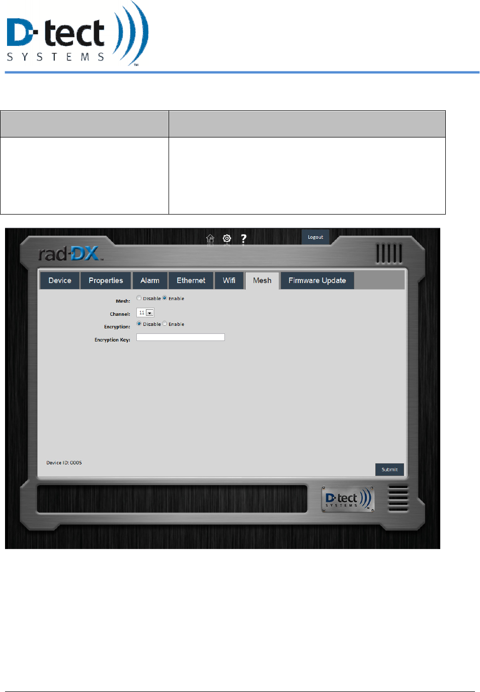
5.4.6 Mesh Tab
Mesh Tab Options Function
Mesh Allows user to configure device to communicate via D-tect
Sensor Net. Not all devices support mesh communication.
You may be required to download an updated firmware
version to establish a mesh network.
Note: The mesh settings are view-only in the current
release.
Figure 15: Mesh Networking Tab
6/12/2012, Rad-DX Manual Version 2.0 Page 22
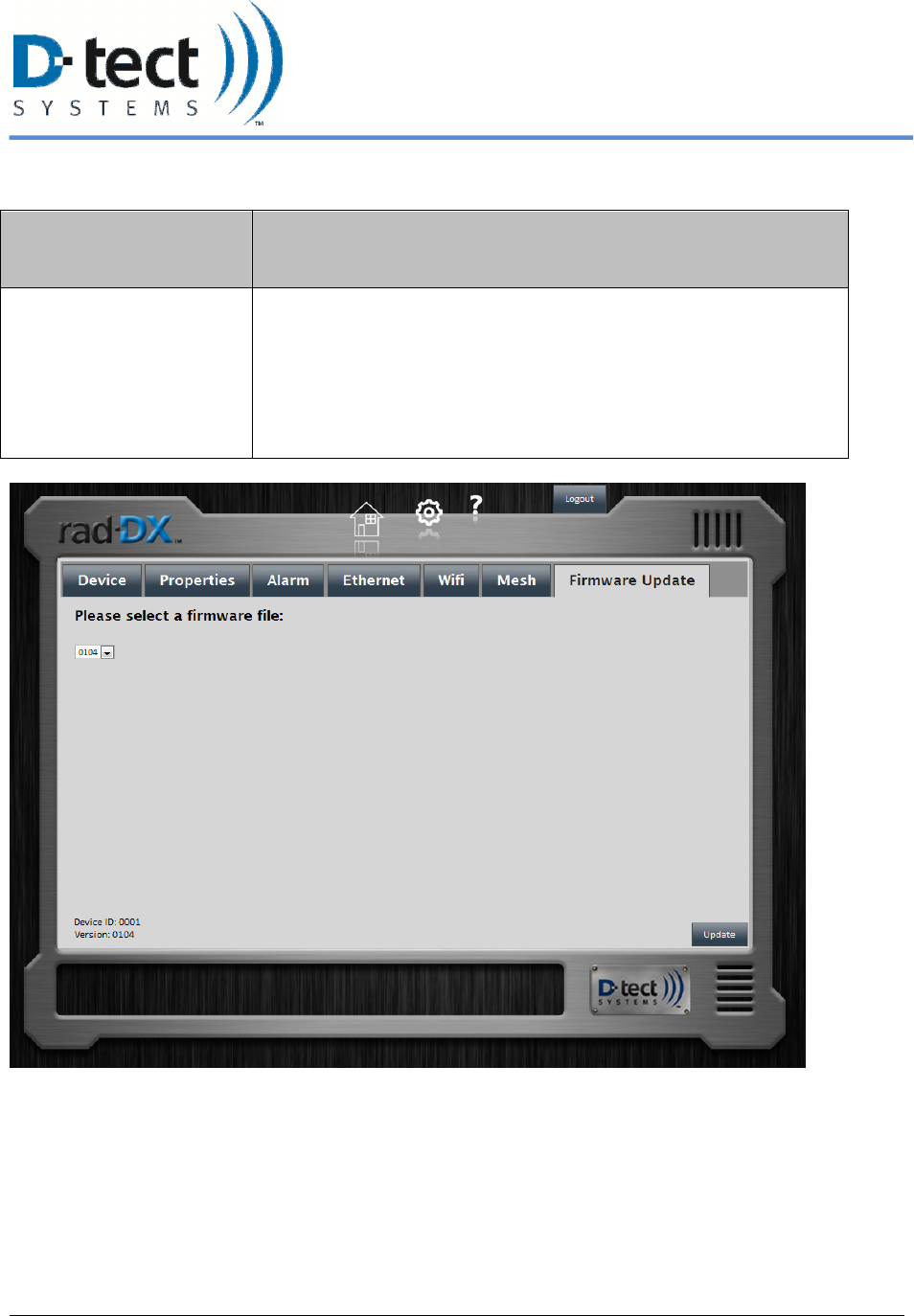
5.4.7 Firmware Update Tab
Firmware Update Tab
Options
Function
Choose file Browse to find the firmware update file (the file name will end in
.tgz). Then click the Send button to start the firmware update. This
will take several minutes. The update file is first transferred to the
Rad-DX unit. Then the Rad-DX unit will show "Updating Device"
on the LCD screen (if present). The top-center blue light will
eventually flash quickly. The unit will automatically reboot and
rejoin the network when the update is complete.
Figure 16: Firmware Update Tab
6/12/2012, Rad-DX Manual Version 2.0 Page 23
6 Installation and Set-up of your Rad-DX
6.1 Physical Installation
The Rad-DX is designed to be either wired and mounted to an electrical junction box or attached
to a wall in close proximity to an outlet.
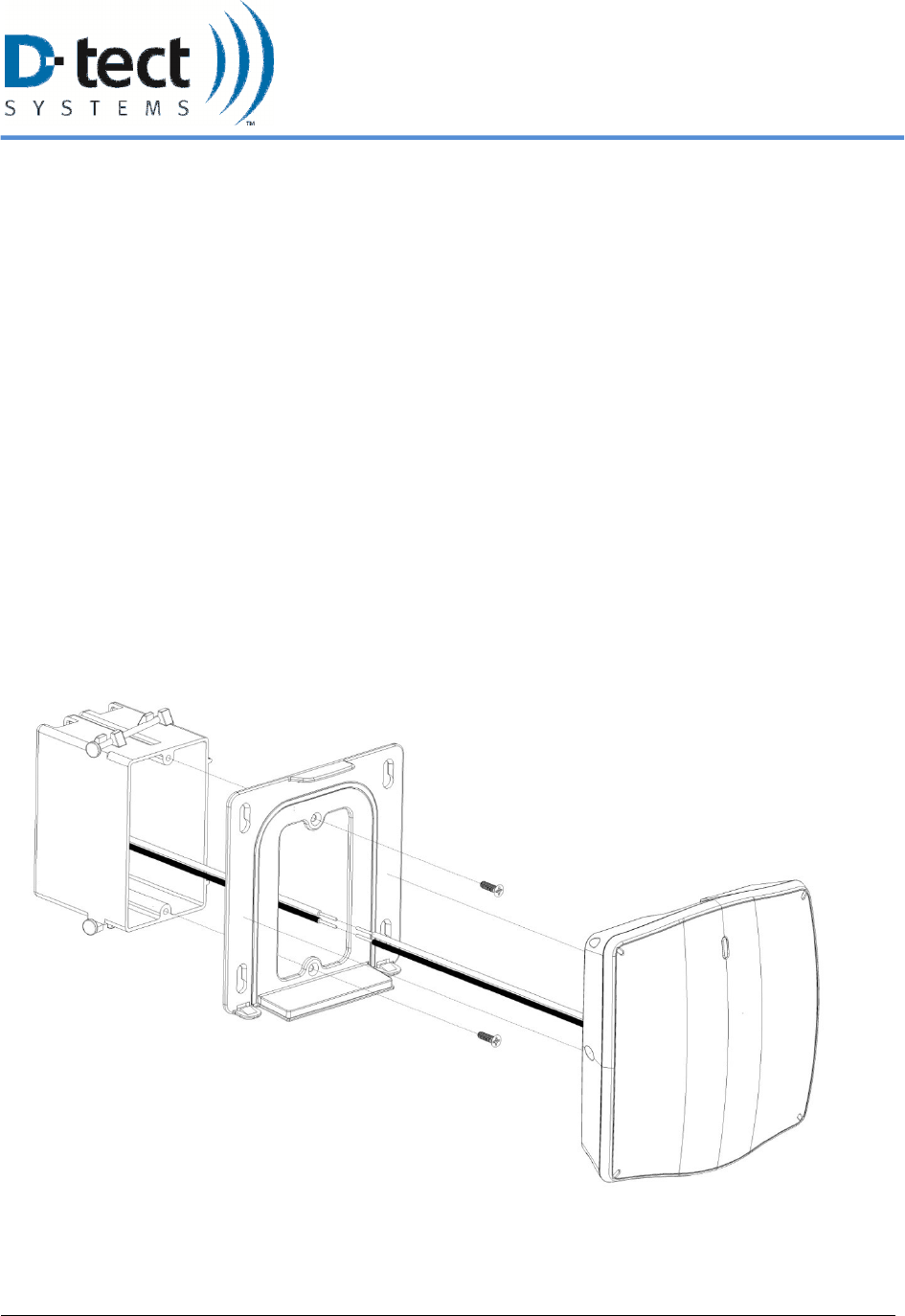
6.1.1 Junction Box Method
Mounting a Rad-DX unit directly to a junction box includes the following steps. Note that an
electrician should complete the installation for quality of the installation and safety of the
installer.
1. Connect the black wire from the “pigtail” wire harness to the black wire in the junction box. Connect
the white wire from the wire harness to the white wire in the junction box.
2. Plug the wire harness into the back of the Rad-DX unit.
3. Mount the Rad-DX wall bracket onto the junction box using the screws included. If a non-standard
junction box is being used, connect the wall bracket to the wall with drywall anchors or wood screws.
4. Press the Rad-DX completely onto the wall bracket and make sure it is secure. It will snap into place.
The Rad-DX can be removed from the bracket by lifting the top tab with a flathead screwdriver.
Figure 17: Junction Box Mounting Method
6/12/2012, Rad-DX Manual Version 2.0 Page 24
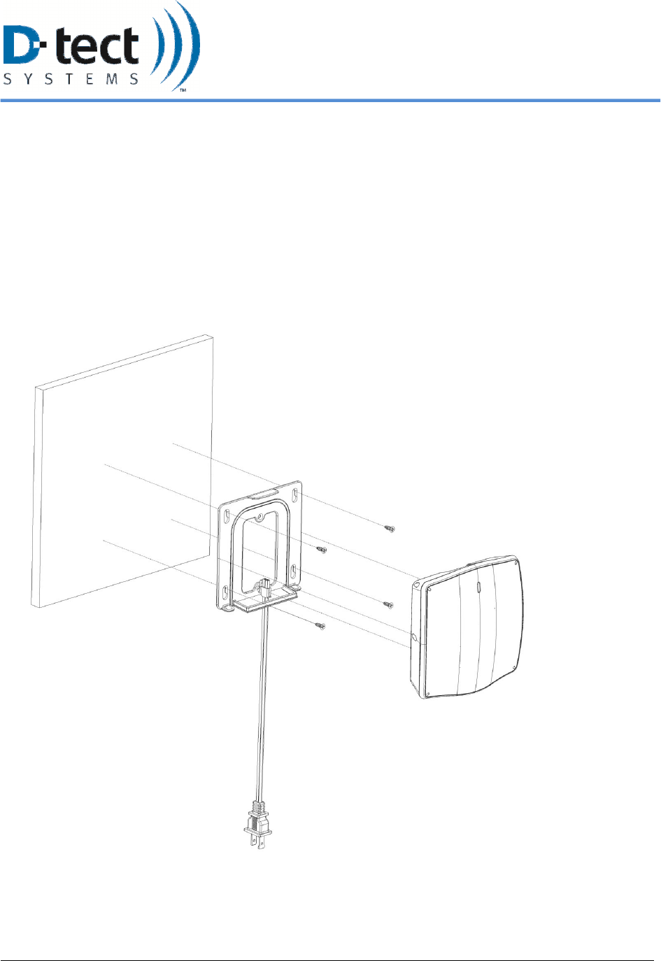
6.1.2 Plug-In Wall Mount Method
To power a Rad-DX unit with A/C power without connection to a junction box, follow these
steps:
1. Mount the Rad-DX wall bracket to the wall using drywall anchors or wood screws.
2. Press the Rad-DX completely onto the wall bracket and make sure it is secure.
3. Connect the A/C power cord to the Rad-DX. Then plug this cord into a nearby outlet.
4. Note: the Plug-In Wall Method is meant for indoor installation: the IP65 rating does not apply to this
method.
Figure 18: Plug-in Wall Mount Method
6/12/2012, Rad-DX Manual Version 2.0 Page 25
6.2 Installing a DX network using the D-tect Cloud Network
6.2.1 User Name and Password
To setup your DX Cloud Network go to http://www.dtectsystems.com/account_setup.html to
complete and submit the form. In this form you will choose the user name(s) and password(s) to
log into your DX Account. Once you have submitted the form you will receive an account
confirmation email with a customer ID within 24 hours. Once you receive your confirmation
email and customer ID proceed to the next section.
6.2.2 DX Utility Application Installation Instructions
1. Follow the Installation Link http://dx.dtectsystems.com/download/DtectDX_Installer.exe to
download the DX Utility Application.
2. Complete the following steps to install and setup the D-tect DX Utility.
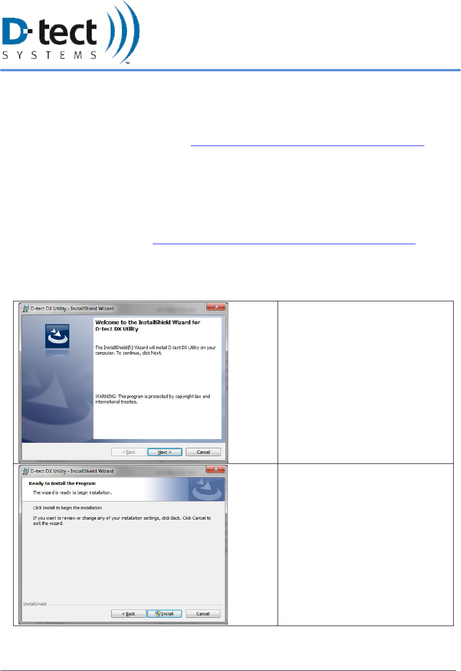
The D-tect DX Utility Setup Wizard
appears. This will allow you to install
the software necessary to operate and
monitor your Rad-DX device.
Click Next to continue.
Click Install to begin the installation
process.
The D-tect DX Utility window will
pop up. Go to the next page.
6/12/2012, Rad-DX Manual Version 2.0 Page 26
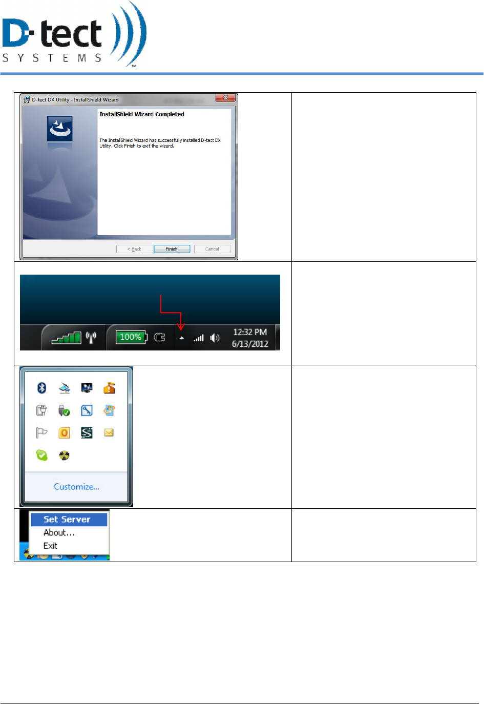
Click Finish to close the Setup
Wizard.
The DX Utility application is located
in your toolbar, which is typically in
the lower right hand portion of your
Windows screen.
The DX Utility application is the
round black and yellow icon in the
toolbar as shown here.
Right click the yellow icon and select
“Set Server”
Typical Toolbar Location
6/12/2012, Rad-DX Manual Version 2.0 Page 27
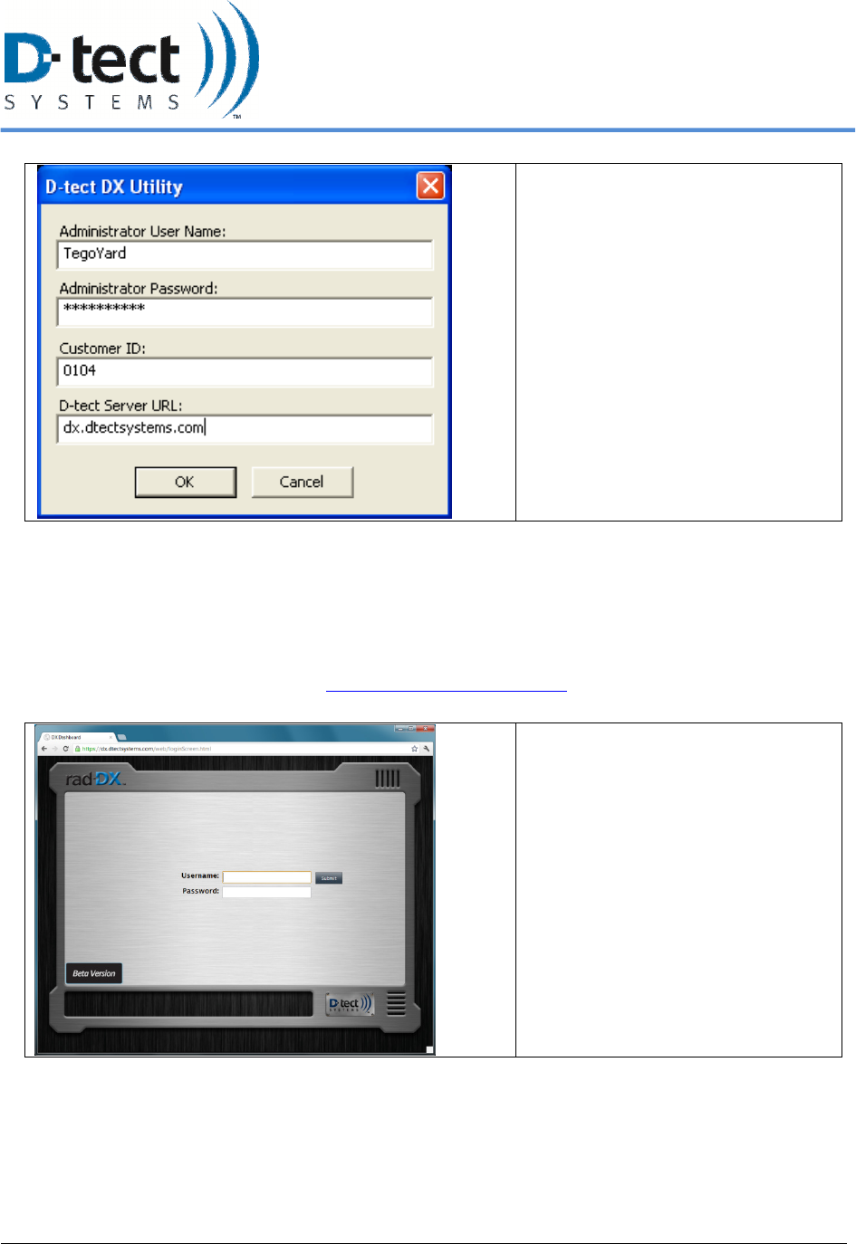
Enter the Administrator User Name,
password, Customer ID and URL and
click OK.
Table 5: Installing the D-tect DX Utility
3. Connect the power cable to the Rad-DX and the plug the power cable in to an outlet located in close
proximity to your computer.
4. Connect your Rad-DX to the PC via the enclosed USB cable.
5. DX Dashboard will automatically open in your default internet browser. You can reach this
website at the following address: https://dx.dtectsystems.com.
D-tect DX Login Page
6/12/2012, Rad-DX Manual Version 2.0 Page 28
D-tect DX Homepage
Your Rad-DX will appear in the page
as a gray icon.
You may click and drag the icon to a
new location and click Save Device
Position.
Click on the gray icon and a Rad-DX
Information window will appear.
Click on the Settings icon on the
lower right portion of the window.
You are now in the Device Settings.
Table 6: Logging into DX Dashboard and Configuring Device Settings
6/12/2012, Rad-DX Manual Version 2.0 Page 29
6. Configure your Rad-DX to communicate with your existing WiFi or Ethernet network.
WiFi
1. Go to the WiFi tab under Device Settings (see above screen shots)
2. Turn on WiFi
3. Enter the SSID name of your network
4. Select the type of security your network uses
5. Enter your network password
6. Select your wireless encryption type
7. Select whether to enable DHCP. By default, DHCP is on. The remainder of the information
fields can be left blank (it will be handled automatically)
8. If DCHP is disabled, fill out the remaining fields (a warning may pop up)
9. Press Submit. A window will pop up saying “Configuring… This may take a minute
10. A second window will pop up saying “Configuration Successful”
• If a window pops up and says “Configuration Failed, check device, then check your Wi-
Fi settings and submit again
11. Return to the Home Screen (the white home icon at the top of the page .). Your gray Rad-
DX icon will turn blue, but this may take a couple of minutes
12. Once the Rad-DX icon turns blue disconnect the USB cable from the Rad-DX device
Table 7: Configuring a Rad-DX with a WiFi network
6/12/2012, Rad-DX Manual Version 2.0 Page 30
Ethernet
1. Go to the Ethernet Tab under Device Settings (see above screen shots)
2. Turn on Ethernet communication
3. Select whether to enable DHCP. By default, DHCP is on. The remainder of the
information fields can be left blank (it will be handled automatically).
4. If DHCP is disabled, please enter your network IP, subnet mask, gateway, and primary
and secondary DNS.
5. Press Submit. A window will pop up saying “Configuring… This may take a minute
6. A second window will pop up saying “Configuration Successful”
• If a window pops up and says “Configuration Failed, check device, then check your
Ethernet settings and submit again
7. Return to the Home Screen (the white home icon at the top of the page .). Your gray
Rad-DX icon will turn blue, but this may take a couple of minutes
8. Once the Rad-DX icon turns blue disconnect the USB cable from the Rad-DX device
Table 8: Configuring a Rad-DX with an Ethernet network
Once your Rad-DX is communicating with your local network, you can monitor and configure
your Rad-DX network via smartphone, tablet, or PC by going to https://dx.dtectsystems.com and
entering your user name and password.
You are now ready to unplug your Rad-DX from the computer and mount it (See Physical
Installation, Section 6.1).
6/12/2012, Rad-DX Manual Version 2.0 Page 31
7 Specifications
Radiation Detectors One 6 cm
3
CsI scintillation crystal with a PMT
Communication D-tect SensorNet mesh network, WiFi, Ethernet, USB
Power 120/240V AC, 50/60 Hz
Backup Power Lithium-ion battery
Measurement Range 1 µR/hr to 100 mR/hr
*Air-kerma dose conversion 1 R = 0.876 REM for per ANSI +N42 32-2006.
Energy Response 59 keV – 2 MeV
Display LCD 4.3” Color TFT / Resolution 480 x 272 / Touch Screen
Units Rem/hr, Sv/hr, CPS
Audible Alarm Piezoelectric buzzer
Alarm Volume > 98dB
Humidity < 95% (non-condensing)
Dimensions 5.97” x 5.92“ x 1.75”
(15.2 cm x 15 cm x 4.4 cm)
Weight Non-LCD version: 0.5 lb (0.2 kg)
LCD version: 0.65 lb (0.3 kg)
Environment IP65 rated for indoor/outdoor operation
Table 9: Rad-DX Specifications

6/12/2012, Rad-DX Manual Version 2.0 Page 32
8 Compliance Requirements
This device complies with part 15 of the FCC rules and Industry Canada ICES-003. Operation is
subject to the following two conditions: (1) This device may not cause harmful interference, and
(2) this device must accept any interference received, including interference that may cause
undesired operation.
Le présent appareil est conforme aux CNR d’Idustrie Canada applicables aux appareils radio
exempts de licence. L’exploitation est autorisée aux deux conditions suivantes: (1) I’appareil ne
doit pas produire de brouillage, et (2) I’utilisateur de I’appareil doit accepter tout brouillage
radioélectrique subi, meme si le brouillage est susceptible d’en compromettre le fonctionnement.
IMPORTANT! Any changes or modifications not expressly approved by the party responsible
for compliance could void the user’s authority to operate this equipment.
IMPORTANT! Tous les changements ou modifications pas expressément approuvés par la partie
responsible de la conformité ont pu vider I’ autorité de I’utilisateur pour actioner cet equipment.
This Class B digital apparatus complies with Canadian ICES-003.
Cet appareil numérique de la classe B est conforme à la norme NMB-003 du Canada.
Note: This equipment has been tested and found to comply with the limits for a Class B digital
device, pursuant to part 15 of the FCC Rules. These limits are designed to provide reasonable
protection against harmful interference in a residential installation. This equipment generates,
uses and can radiate radio frequency energy and, if not installed and used in accordance with the
instructions, may cause harmful interference to radio communications. However, there is no
guarantee that interference will not occur in a particular installation. If this equipment does cause
harmful interference to radio or television reception, which can be determined by turning the
equipment off and on, the user is encouraged to try to correct the interference by one or more of
the following measures:
• Reorient or relocate the receiving antenna.
• Increase the separation between the equipment and receiver.
• Connect the equipment into an outlet on a circuit different from that to which the receiver
is connected.
• Consult the dealer or an experienced radio/TV technician for help.

6/12/2012, Rad-DX Manual Version 2.0 Page 33
FCC Radiation Exposure Statement
This equipment complies with FCC radiation exposure limits set forth for an uncontrolled
environment. This equipment should be installed and operated with minimum distance 20cm
between the radiator and your body.
For Industry Canada
Important Note:
Radiation Exposure Statement:
This equipment complies with IC radiation exposure limits set forth for an uncontrolled
environment. This equipment should be installed and operated with minimum distance 20cm
between the radiator and your body.
Note Importante: (Pour l’utilisation de dispositifs mobiles)
Declaration d’exposition aus radiations:
Cet équipement est conforme aux limites d´exposition aux rayonnements IC établies pour un
environnement non contrôlé. Cet équipment doit être installé et utilisé avec un mimimum de 20
cm de distance entre la source de rayonnement et votre corps.
9 Technical Support
Phone: 801-495-2310
Email: techsupport@dtectsystems.com

6/12/2012, Rad-DX Manual Version 2.0 Page 34
Warranty for D-tect System Products
1. What this Warranty Covers and for How Long
D-tect Systems (“D-tect Systems”) warrants this device (the "Product") against defects in materials and
workmanship under normal use for a period of two years from the date of purchase. This warranty extends to the
first end-user purchaser only, and is not transferable. This warranty does not extend to other ancillary and/or
consumable products including but not limited to batteries, calibration sources, straps, and shipping cases. D-tect
Systems, at its option, will at no charge either repair, replace or refund the purchase price of any Products that do not
conform with this warranty. Repair may include the replacement of parts with functionally equivalent reconditioned
or new parts. Replacement may include providing a functionally equivalent Certified Reconditioned/Pre-owned or a
new Product. Products that have been repaired or replaced are warranted for the balance of the original warranty
period or for 90 days from the date that the repaired or replaced Product is received by you, whichever is longer. All
Products for which replacements have been provided will become D-tect Systems property.
2. Other Warranty Conditions
This warranty is D-tect Systems’ complete warranty for the Product. D-tect Systems assumes no obligation or
liability for changes to this warranty unless made in writing and signed by an officer of D-tect Systems.
If D-tect Systems agrees to perform services requested and approved by the customer that are not included in either
the Limited or Extended Warranty, these services will be billed to the customer at D-tect Systems’ standard prices
and terms.
D-tect Systems does not warrant any installation, maintenance, or service that it did not perform. SERVICE WORK
PERFORMED BY SERVICE CENTERS NOT AUTHORIZED BY D-TECT SYSTEMS TO PERFORM SUCH
WORK WILL VOID THIS WARRANTY.
3. What This Warranty Does Not Cover
a. Defects or damage resulting from: collision of the Product with hard surfaces, contact with water, rain or
extreme humidity, contact with sand, dirt or the like, contact with extreme heat or cold, spills of food or
liquid, improper testing, operation, maintenance, installation, adjustment; or any alteration or modification
of any kind.
b. Normal “wear and tear” of the Product such as scratches, scuffs, and marks on the LCD, case and other
external features.
c. Cracked or broken displays, buttons, or damage to other externally exposed parts caused by abnormal use
and/or abuse of the Product.
d. Products disassembled or repaired in such a manner as to adversely affect performance or prevent adequate
inspection and testing to verify any warranty claim.
e. Products on which serial numbers or date tags have been removed, altered or obliterated.
4. How to Get Warranty Service
To get warranty service, please contact your distributor or D-tect Systems at www.dtectsystems.com .
You will receive directions on how to mail the Product to D-tect Systems. All Products shipped to D-tect Systems
must be shipped with freight and insurance prepaid. Along with the Product you must include a receipt, bill of sale,
or some other comparable proof of purchase, a written description of the problem and, most importantly, your

6/12/2012, Rad-DX Manual Version 2.0 Page 35
address and telephone number. If additional information is needed, please contact D-tect Systems at the web address
indicated above.
5. General Provisions
THIS IS THE COMPLETE WARRANTY FOR THIS PRODUCT BY D-TECT SYSTEMS AND SETS FORTH
YOUR EXCLUSIVE REMEDIES. THIS WARRANTY IS GIVEN IN LIEU OF ALL OTHER EXPRESS
WARRANTIES. IMPLIED WARRANTIES, INCLUDING WITHOUT LIMITATION THE IMPLIED
WARRANTIES OF MERCHANTABILITY AND FITNESS FOR A PARTICULAR PURPOSE, ARE GIVEN
ONLY IF SPECIFICALLY REQUIRED BY APPLICABLE LAW. OTHERWISE, THEY ARE SPECIFICALLY
EXCLUDED. IN NO EVENT SHALL D-TECT SYSTEMS BE LIABLE FOR DAMAGES IN EXCESS OF THE
PURCHASE PRICE OF THE PRODUCT OR FOR ANY INDIRECT, INCIDENTAL, SPECIAL OR
CONSEQUENTIAL DAMAGES ARISING OUT OF THE USE OR INABILITY TO USE THE PRODUCT, TO
THE FULL EXTENT THESE DAMAGES MAY BE DISCLAIMED BY LAW.
6. Patent and Software Provisions
D-tect Systems will defend at its own expense, any suit brought against you to the extent that it is based
on a claim that the Products infringe a United States patent. D-tect Systems will pay those costs and
damages finally awarded against you in any such suit which is attributable to any such claim. The
defense and payments by D-tect Systems are conditioned on the following: (a) that you will notify D-tect
Systems promptly in writing any notice of the claim; and (b) that D-tect Systems will have sole control of
the defense of the suit and all negotiations for its settlement or compromise; and (c) should the Products
become, or in D-tect System’s opinion be likely to become, the subject of a claim of infringement of a
United States patent, that you will permit D-tect Systems, at its option and expense, either: to procure for
you the right to continue using the Products or parts; to replace or modify them so that they become non-
infringing; or to grant you a credit for such Products or parts as depreciated and accept their return. The
depreciation will be an equal amount per year over the lifetime of the Products, accessories, battery or
parts as established by D-tect Systems.
D-tect Systems will have no liability to you with respect to any claim of patent infringement which is
based upon the combination of the Products or parts furnished under this limited warranty with software,
apparatus or devices not furnished by D-tect Systems. D-tect Systems will have no liability for the use of
ancillary or peripheral equipment or software not furnished by D-tect Systems which is attached to or
used in connection with the Products. The foregoing states the entire liability of D-tect Systems with
respect to infringement of patents by the Products, accessories, batteries or any parts of them.
Laws in the United States and other countries preserve for D-tect Systems certain exclusive rights for
copyrighted D-tect Systems software such as the exclusive rights to reproduce in copies and distribute
copies of the D-tect Systems software. D-tect Systems software may be copied into, used in and
redistributed with only the Products associated with such D-tect Systems software. No other use,
including without limitation disassembly, of such D-tect Systems software or exercise of exclusive rights
in such D-tect Systems software is permitted.