Visionary VMX-100 2.4GHz Transmitter User Manual VMX 100 SPP Preliminary Datasheet
Visionary Products, Inc. 2.4GHz Transmitter VMX 100 SPP Preliminary Datasheet
Manual
Version 0.8, October 27, 2003 Proprietary to VPrf.com 1
VMX-100-SPP Preliminary Datasheet
General Description
The VMX-100-SPP is a 2.4 GHz Bluetooth radio (or modem) that acts as a wireless transceiver.
Integrating the VMX-100-SPP into a device and setting up Bluetooth serial communication
enables that device to send and receive wireless communication to/from other Bluetooth-enabled
devices.
Features
• Small Size: The VMX-100 Wireless Modem has been engineered to be a very small size
- only 1.44" x 1.335".
• Simple Integration: Using VMX-100 Wireless Modems eliminates the need for expensive
RF engineering and development for your product.
• Fast Time to Market: Using the VMX-100 Wireless Modem reduces the time to market
for your wireless product.
• Highly Customizable: VPrf.com gives you the flexibility you need for your specific
application by offering wireless radio customization and integration services.
• Extended Range: VMX-100 Wireless Modems transmit and receive Bluetooth signals up
to 100 meters (328 feet) with embedded antennas.
• Low Power Consumption: Power management becomes easier with the low power
consumption of the VMX-100 Wireless Modem.
Applications
• Consumer Products
• Medical Devices
• Industrial Products
• Handheld Devices
• Military Devices
• Government Applications
Ordering Information
Part Number Description
VMX-100-SPP Bluetooth Modem with embedded Serial Port Profile and integrated
PCB antenna.
VMX-Evaluation Kit
Evaluation kit for VMX Bluetooth Modems. Includes one VMX-100-
SPP module, one VMX-RS232 Interface Adapter, one Bluetooth
USB Adapter, one 9-pin RS232 serial cable, one AC power
adapter, and instructions.
Version 0.8, October 27, 2003 Proprietary to VPrf.com 2
Key Specifications
General Specifications
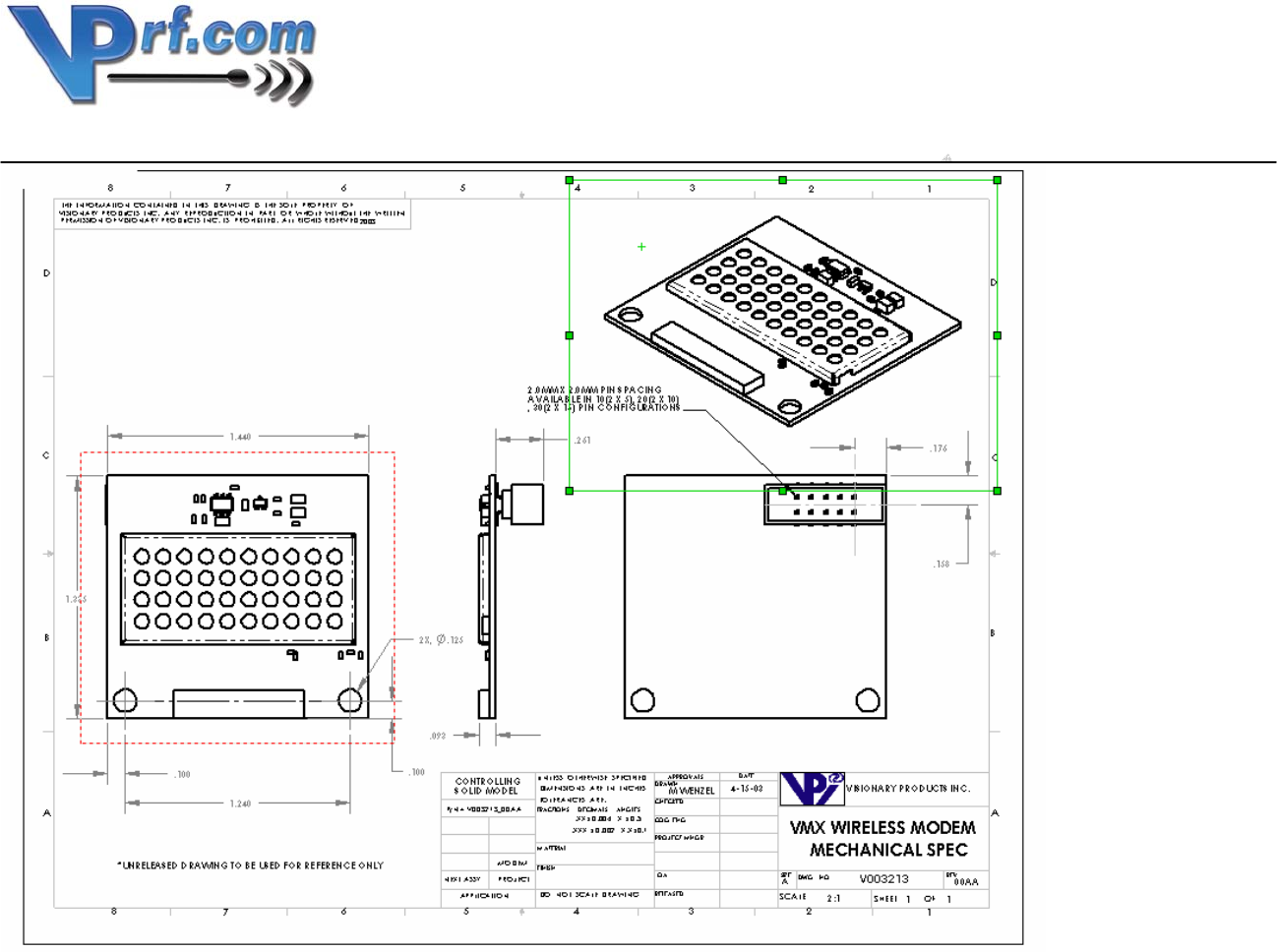
Board Size with Connector 1.44" x 1.335" x 0.385" (36.58mm x
33.91mm x 9.78mm)
Weight 0.3 oz.
Frequency 2.4 GHZ - ISM band
Bluetooth Class Class I
Emission Type Frequency hopping spread spectrum
(FHSS GFSK)
RF Data Rate 1 Mbps
Data Throughput 723 kbps maximum
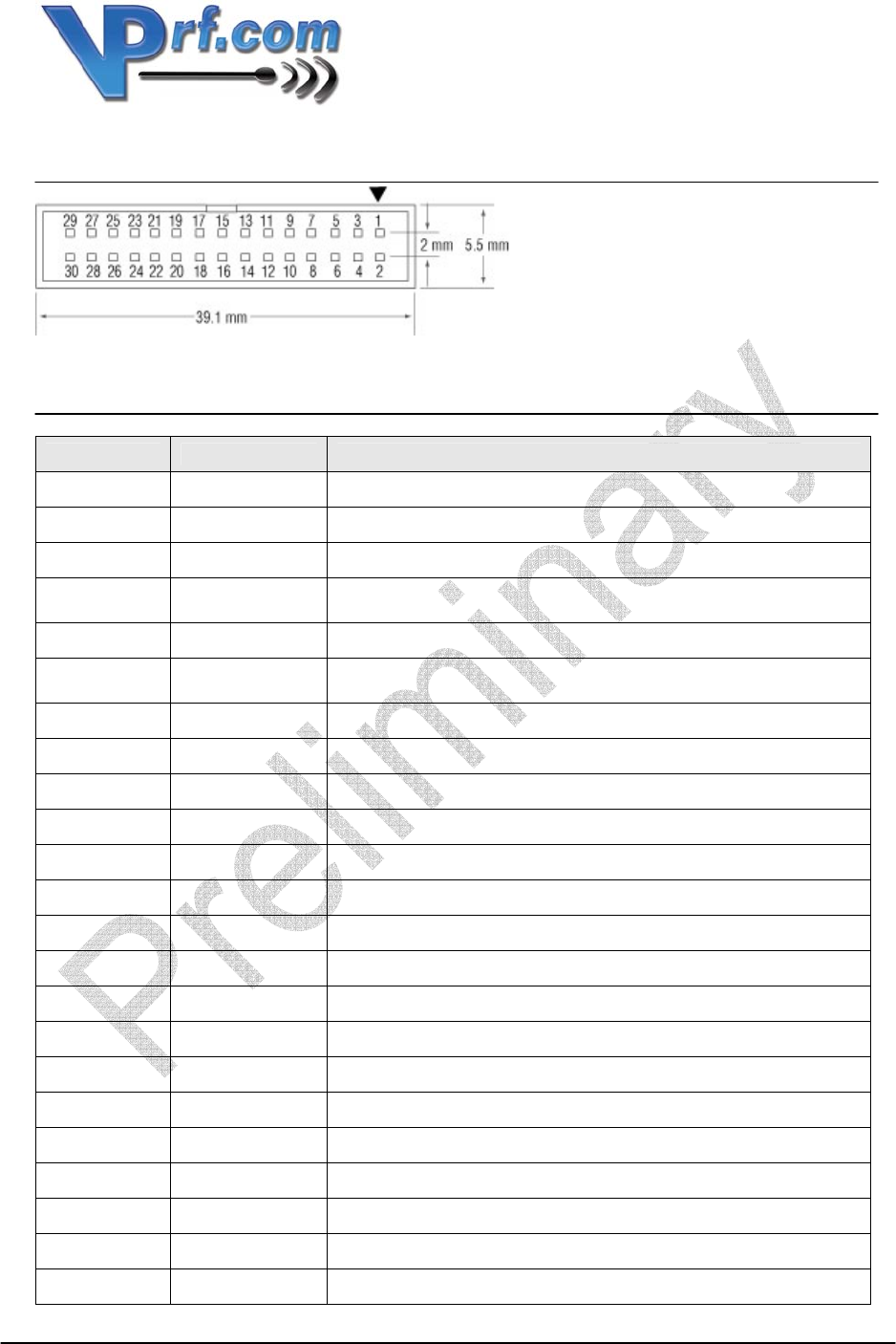
Connector 30 pins, 2 rows, 2 mm pin spacing
Operating Temperatures 0° to 70° C (commercial)
Antenna Internal Embedded antenna
External Connector for external antenna*
*May require additional FCC testing.
Power Requirements
Supply Voltage 3.3 - 5 volts unregulated
Transmit Current 125 mA
Receive Current 60 mA
Sleep Mode Current 100 µA
Shutdown Mode Current 0.1 µA
Transmit Power Output 100 mW maximum (20 dBm)
Max. Sleep Time to Maintain Sync 1.28 seconds recommended
Compatibility & Certification
FCC FCC Modular Approval
Bluetooth Bluetooth 1.1 Compatible
Distance Range 100 m (330 feet) open range
Interface 30 Pin Interface UART, USB, and audio interfaces
(standard)
Power Consumption
ACL Data Transfer
720kbps USB (Slave) 140 mA
ACL Connection, Sniff Mode, 40ms
Interval, 38.4kbps UART 10 mA
ACL connection, Sniff Mode 1.28s
interval, 38.4kbps UART 2 mA
Version 0.8, October 27, 2003 Proprietary to VPrf.com 3
Pin Diagram
Pin Description
Pin Number Name Description/Function
1 GND Ground
2 VCC 3.3V to 5.5V unregulated power supply
3 RESET(L) Reset if low - must be low for >5ms
4 UART_CTS(L)
UART clear to send input - active low - connect to your RTS
output
5 GND Ground
6 UART_RTS(L)
UART request to send output - active low - connect to your
CTS input
7 UART_TX UART data output to your device's RX
8 UART_RX UART data input to your device's TX
9 GPIO_1 VPrf programmable input/output line
10 SHUTDOWN(L) Power shutdown to entire module - active low
11 SPI_MISO Serial peripheral interface data output
12 GPIO_2 VPrf programmable input/output line
13 GND Ground
14 SPI_CSB Chip select for serial peripheral interface
15 USB_D+ USB data plus
16 USB_D- USB data minus
17 SPI_MOSI Serial peripheral interface data input
18 GND Ground
19 GPIO_3 VPrf programmable input/output line
20 SPI_CLK Serial peripheral interface clock
21 PCM_SYNC Audio synchronous data SYNC
22 PCM_IN Audio synchronous data input
23 PCM_CLK Audio synchronous data
Version 0.8, October 27, 2003 Proprietary to VPrf.com 4
24 PCM_OUT Audio synchronous data
25 GPIO_4 VPrf programmable input/output line
26 GND Ground
27 GPIO_5 VPrf programmable input/output line
28 GPIO_6 VPrf programmable input/output line
29 VCC 3.3V to 5.5V unregulated power supply
30 GND Ground
(L) – Indicates an active low signal
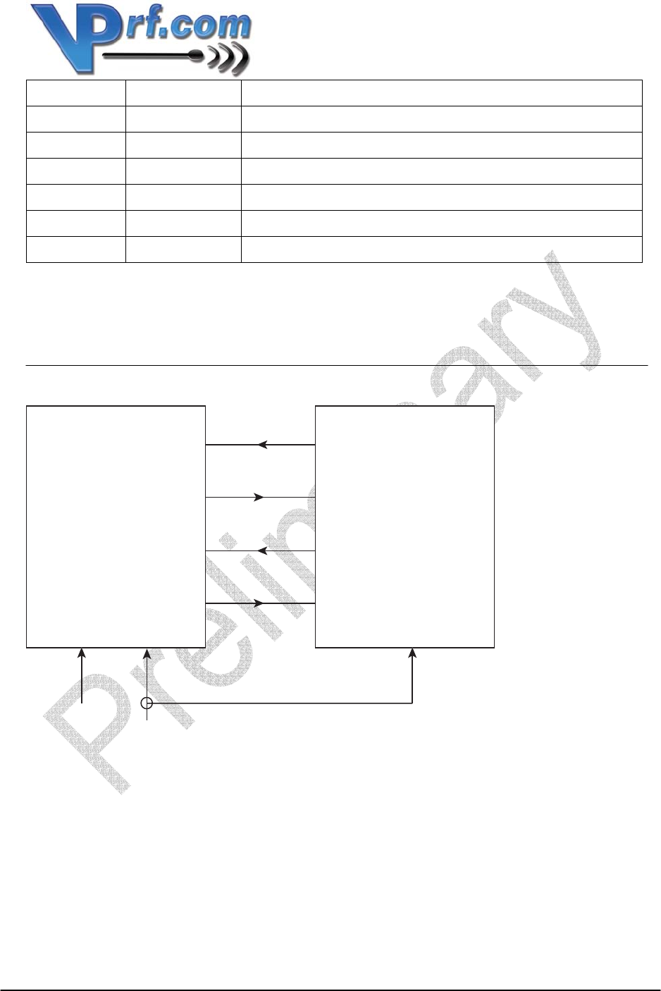
Wiring Diagram
Pin 2 Pin 1
Pin 8
Pin 7
Pin 4
Pin 6
Ground
VCC
UART_TX
UART_RX
RTS
CTS
UART_TX
UART_RX
RTS
CTS
VMX Customer Device
Version 0.8, October 27, 2003 Proprietary to VPrf.com 5
Electrical Characteristics
Parameter Minimum Typical Maximum
Absolute Maximum VCC 5.5V
Absolute Minimum VCC 3.15V
Input Logic Level Low -0.4V 0.8V
Input Logic Level High 2.1V 3.4V
Output Logic Level Low 0.2V
Output Logic Level High 2.8V
Default UART Settings
Parameter Setting
Baud Rate 57,600
Data Bits 8
Parity None
Stop Bits 1
Hardware Flow Control Enabled
Version 0.8, October 27, 2003 Proprietary to VPrf.com 6
Mechanical Drawing